Patent application title: SELF-ALIGNING SUBSEA STRUCTURES
Inventors:
Charles Donald Lawson (Aberdeenshire, GB)
Assignees:
AKER SUBSEA LIMITED
IPC8 Class: AE02D2752FI
USPC Class:
4051951
Class name: Hydraulic and earth engineering marine structure or fabrication thereof
Publication date: 2014-11-20
Patent application number: 20140341656
Abstract:
A subsea assembly comprises a first structure (1) including a plurality
of substantially parallel guide posts (4) and a second structure (2)
comprising a support and depending therefrom a plurality of tubular
receptacles (12) each positioned for fitment on a respective one of the
guide posts. At least one of the receptacles includes a plurality of
longitudinally disposed semi-elliptical springs (15) disposed to engage
the exterior of the respective guide post (4) and thereby to axially
centre the receptacle with respect to the guide post. In a converse
arrangement at least one of the posts (4) carries a plurality of
longitudinally disposed semi-elliptical springs (15) disposed to engage
the interior of the respective receptacle (12) and thereby to axially
centre the receptacle with respect to the guide post.Claims:
1. A subsea structure for deployment on a plurality of substantially
parallel guide posts comprising: a support and depending therefrom a
plurality of tubular receptacles each positioned for fitment on a
respective one of the guide posts; wherein at least one of the
receptacles includes a plurality of longitudinally disposed
semi-elliptical springs disposed to engage the exterior of the respective
guide post and thereby to axially centre the receptacle with respect to
the guide post.
2. A subsea structure according to claim 1 in which each spring secured to a respective receptacle at one end and is adjustably supported with respect to that receptacle at its other end.
3. A subsea structure according to claim 2 in which the said other end of the spring is supported by a member which is captive within the respective receptacle.
4. A subsea structure according to claim 3 in which each spring has at each end an axially extending foot.
5. A subsea structure according to claim 1 in which there are four springs disposed at 90.degree. degree intervals about the axis of a receptacle, so as to provide a centring action for orthogonal directions laterally of the respective post.
6. A subsea assembly comprising: a first structure comprising a plurality of substantially parallel guide posts; a second structure comprising a support and depending therefrom a plurality of tubular receptacles each positioned for fitment on a respective one of the guide posts; wherein at least one of the receptacles includes a plurality of longitudinally disposed semi-elliptical springs disposed to engage the exterior of the respective guide post and thereby to axially centre the receptacle with respect to the guide post.
7. A subsea assembly according to claim 6 in which each spring is secured to a respective receptacle at one end and is adjustably supported with respect to that receptacle at its other end.
8. A subsea assembly according to claim 7 in which the said other end of the spring is supported by a member which is captive within the respective receptacle.
9. A subsea assembly according to claim 8 in which each spring has at each end an axially extending foot.
10. A subsea assembly according to claim 6 in which there are four springs disposed at 90.degree. degree intervals about the axis of a receptacle, so as to provide a centring action for orthogonal directions laterally of the respective post.
11. A subsea assembly according to claim 6 in which the first structure comprises a central post around which the said guide posts are disposed and the second structure comprises a cooperative part disposed for fitment over the central post.
12. A subsea structure comprising a plurality of substantially parallel guide posts wherein, for the reception of a second structure which comprises a support and depending therefrom a plurality of tubular receptacles each positioned for fitment on a respective one of the guide posts, at least one of the posts carries a plurality of longitudinally disposed semi-elliptical springs disposed to engage the interior of the respective receptacle and thereby to axially centre the receptacle with respect to the guide post.
13. A subsea structure according to claim 12 in which each spring is secured to a respective post at one end and is adjustably supported with respect to that post at its other end.
14. A subsea structure according to claim 13 in which the said other end of the spring is supported by a member which is captive within the respective spring.
15. A subsea structure according to claim 14 in which each spring has at each end an axially extending foot.
16. A subsea structure according to claim 12 in which there are four springs disposed at 90.degree. degree intervals about the axis of a post, so as to provide a centring action for orthogonal directions laterally of the respective post.
17. A subsea assembly according to claim 12 in which each of a plurality of the receptacles includes a plurality of longitudinally disposed semi-elliptical springs disposed to engage the exterior of a respective guide post and thereby to axially centre the receptacle with respect to the respective guide post.
18. A subsea assembly comprising: a first structure comprising a plurality of substantially parallel guide posts; a second structure comprising a support and depending therefrom a plurality of tubular receptacles each positioned for fitment on a respective one of the guide posts; wherein at least one of the posts carries a plurality of longitudinally disposed semi-elliptical springs disposed to engage the interior of the respective receptacle and thereby to axially centre the receptacle with respect to the guide post.
19. A subsea assembly according to claim 18 in which each spring is secured to a respective post at one end and is adjustably supported with respect to the post at its other end.
20. A subsea assembly according to claim 19 in which the said other end of the spring is supported by a member which is captive within the respective spring.
21. A subsea assembly according to claim 20 in which each spring has at each end an axially extending foot.
22. A subsea assembly according to claim 18 in which there are four springs disposed at 90.degree. degree intervals about the axis of a post, so as to provide a centring action for orthogonal directions laterally of the respective post.
23. A subsea assembly according to claim 18 in which the first structure comprises a central post around which the said guide posts are disposed and the second structure comprises a cooperative part disposed for fitment over the central post.
24. A subsea assembly according to claim 18 in which each of the posts carries a plurality of longitudinally disposed semi-elliptical springs disposed to engage the interior of a respective receptacle and thereby to axially centre the receptacle with respect to the respective guide post.
Description:
FIELD OF THE INVENTION
[0001] This invention relates to subsea structures and to the facilitation of alignment of those structures.
BACKGROUND TO THE INVENTION
[0002] It is known to provide an assembly of subsea structures of which a first structure comprises a base and a plurality of substantially parallel guide posts extending from the base and of which a second structure comprises a support and depending therefrom a plurality of tubular receptacles each positioned for fitment on a respective one of the guide posts. The ordinary purpose of such an assembly is to allow accurate mating of the structures, for example to allow connection of a marine riser to a subsea installation. The latter may incorporate the first structure and include a boss which may be centrally located relative to the guide posts. The second structure may have a cooperative part which can engage the boss to provide connection of the marine riser to a passageway within the boss. However, the invention is applicable to other kinds of structures.
[0003] A general problem arises from the difficulty of causing engagement of these and similar structures in accurate alignment. One structure is often tilted with respect to the other and consequently is quite liable to bind or jam. It would be desirable to provide an assembly in which correct alignment of the posts and receptacles were facilitated, whereby to avoid, or at least lessen the need for, manipulation of the structures by a diver or a remotely operated vehicle (ROV), and to allow engagement and disengagement at greater degrees of angular or positional misalignment.
SUMMARY OF THE INVENTION
[0004] In one embodiment the invention subsists in a subsea structure for deployment on a plurality of substantially parallel guide posts, comprising a support and depending therefrom a plurality of tubular receptacles each positioned for fitment on a respective one of the guide posts; wherein at least one of the receptacles includes a plurality of longitudinally disposed semi-elliptical springs disposed to engage the exterior of the respective guide post and thereby to axially centre the receptacle with respect to the guide post.
[0005] In another aspect the invention subsists in a subsea assembly, comprising a first structure comprising a plurality of substantially parallel guide posts; a second structure comprising a support and depending therefrom a plurality of tubular receptacles each positioned for fitment on a respective one of the guide posts; wherein at least one of the receptacles includes a plurality of longitudinally disposed semi-elliptical springs disposed to engage the exterior of the respective guide post and thereby to axially centre the receptacle with respect to the guide post.
[0006] Each spring may be secured to a respective receptacle at one end and be adjustably secured to that receptacle at its other end. The said other end of the spring may be supported by a member which is captive within the respective receptacle. Each spring may have at each end an axially extending foot. There may be four springs disposed at 90° degree intervals about the axis of a receptacle, so as to provide a centring action for orthogonal directions laterally of the respective post. However, other numbers of springs may be suitable.
[0007] In a specific example all the receptacles may have springs as aforesaid.
[0008] In another aspect of the invention a converse arrangement is used, wherein the springs are carried on at least one of the posts instead of within a receptacle. However, the centering action is the same.
[0009] Thus the invention also provides a subsea structure comprising a plurality of substantially parallel guide posts wherein, for the reception of a second structure which comprises a support and depending therefrom a plurality of tubular receptacles each positioned for fitment on a respective one of the guide posts, at least one of the posts carries a plurality of longitudinally disposed semi-elliptical springs disposed to engage the interior of the respective receptacle and thereby to axially centre the receptacle with respect to the guide post.
[0010] According to this aspect of the invention a subsea assembly comprises a first structure comprising a plurality of substantially parallel guide posts; and a second structure comprising a support and depending therefrom a plurality of tubular receptacles each positioned for fitment on a respective one of the guide posts; wherein at least one of the posts carries a plurality of longitudinally disposed semi-elliptical springs disposed to engage the interior of the respective receptacle and thereby to axially centre the receptacle with respect to the guide post.
[0011] Each spring may be secured to a respective post at one end and be adjustably supported with respect to the post at its other end. The said other end of the spring may be supported relative to the respective post by a member which is captive within the respective spring. Each spring may have at each end an axially extending foot.
[0012] As before there may be four springs disposed at 90° degree intervals about the axis of a post, so as to provide a centering action for orthogonal directions laterally of the respective post. In a specific example all the posts may have springs as aforesaid.
[0013] The first structure may comprise a central post around which the said guide posts are disposed and the second structure may comprise a cooperative part disposed for fitment over the central post.
BRIEF DESCRIPTION OF THE DRAWINGS
[0014] FIG. 1 is a plan view of one structure according to a preferred embodiment of the invention;
[0015] FIG. 2 is a sectional view of two structures according to a preferred embodiment of the invention;
[0016] FIG. 3 is a sectional view of two structures according to one embodiment of the invention;
[0017] FIG. 4 is a detail of the embodiment shown in FIG. 3;
[0018] FIG. 5 is a view showing structures which are misaligned but otherwise similar to FIG. 3, which shows structures which are aligned;
[0019] FIG. 6 is a detail on the arrow A in FIG. 5;
[0020] FIG. 7 is a sectional view of two structures according to another embodiment of the invention;
[0021] FIG. 8 is a detail of the embodiment shown in FIG. 7;
[0022] FIG. 9 is a view showing structures which are misaligned but otherwise similar to FIG. 7, which shows structures which are aligned; and
[0023] FIG. 10 is a detail on the arrow A in FIG. 9.
DESCRIPTION OF PREFERRED EMBODIMENTS
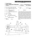
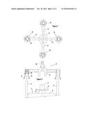
[0024] FIGS. 1 and 2 illustrate two structures 1 and 2 which embody one example of the invention. In this example the structure 1 is intended to be a lower of the two structures and the structure 2 is intended to be lowered onto the first structure 1 in order to make some operative connection when the structures are fully engaged. However, the assembly may be inverted. Moreover, the direction of engagement may be oblique or at right angles to the vertical.
[0025] In the present example the structure 1 comprises a casing 3 for a subsea installation that may be part of a module, manifold, well or other equipment. In this example two or more substantially parallel guide posts 4 extend upwardly from the structure 1. Typically there may be four such posts, to provide ultimately stability of the structure 2 about two horizontal axes but the actual number depends on design choice. Only two of the four posts are shown in FIG. 2.
[0026] The structure 1 includes at its upper side a post 5 which supports a peripheral platform 6. This platform is a datum for the central part of the structure 2. A top part 7 of the post 5 extends above the platform. It may be hollow so as to allow (for example) fluid flow. In this example the post is disposed centrally between the guide posts 4.
[0027] The structure 2 comprises a central portion 8 which comprises a part 9 for cooperation with the post 5. The part 9 is in this example an inverted bucket which can fit over the post 5. An upper part of the central portion of the structure 2 is a marine riser 10 which is in communication with the interior of the bucket 9.
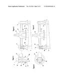
[0028] Extending laterally from the central portion of the structure 2 are lateral arms 11 each of which supports a tubular receptacle 12 each of which corresponds to one of the guide posts and is positioned to receive the respective guide posts as the structure 2 is lowered towards the structure 1. The receptacles are all similar and only the left-hand receptacle 12a in FIGS. 1 and 2 will be described mainly with reference to FIG. 4, which illustrates to a larger scale the detail within the circle X in FIG. 3.
[0029] The receptacle 12a has a straight tubular portion 13 of constant cross section and an outwardly flared lower rim 14. This constitutes a docking cone which facilitates initial engagement of the receptacle and post when as usual they are not initially axially aligned. Within the portion 13 are disposed semi-elliptical springs 15. There may be two opposed springs but preferably as shown there are four springs in two orthogonal pairs. Each spring is disposed lengthwise in the portion 13. It is fixed to the portion at its upper end at or near the upper rim of the portion 13. At its other end the spring is supported by a member 18 which extends through a respective hole 17 in the portion 13. The member is captive within the hole (which may be threaded) but allows movement of the lower end of the spring 15 relative to the tubular portion 13. The member 18 may be a bolt extending through the portion 13 to contact the foot of the spring 15. It may be adjusted lengthwise to set an adjustable radial limit for the spring and can be locked in position by a securing nut 16. Each spring has a small axially extending foot at each end. The foot 19 at the upper end allows securing of the upper end by welding whereas the foot 20 at the lower end enables sliding movement of the lower end with respect to the member 18.
[0030] The springs in each receptacle engage slidingly the outer surface of the guide post 4 and provide an automatic centering action. For this purpose the springs should be substantially similar in shape and spring rate. In this example the centering action is along two axes normal to the axis of the post 4.
[0031] FIGS. 3 and 4 illustrate the structures 1 and 2 when they have been mutually engaged correctly.
[0032] FIG. 5 illustrates the structure 1 and 2 when as will frequently occur there is obliquity in the approach of the structures as indicated by the curved arrow B. FIG. 6 is a plan view on arrow A of the receptacle 12a and its post in this condition. The obliquity can be accommodated by the springs and corrected to leave the structures in the positions shown in FIG. 3.
[0033] A second embodiment of the invention is illustrated in FIGS. 7 to 10. As is shown in FIG. 7 the structure 1 as before comprises a casing 3 for a subsea installation that may be part of a module, manifold, well or other equipment. In this example two or more substantially parallel guide posts 4 extend upwardly from the structure 1. Typically there may be four such posts, to provide ultimately stability of the structure 2 about two horizontal axes but the actual number depends on design choice. Only two of the four posts are shown in FIG. 2.
[0034] The structure 1 includes at its upper side a post 5 which supports a peripheral platform 6. This platform is a datum for the central part of the structure 2. A top part 7 of the post 5 extends above the platform. It may be hollow so as to allow (for example) fluid flow. In this example the post is disposed centrally between the guide posts 4.
[0035] The structure 2 comprises a central portion 8 which comprises a part 9 for cooperation with the post 5. The part 9 is in this example an inverted bucket which can fit over the post 5. An upper part of the central portion of the structure 2 is a marine riser 10 which is in communication with the interior of the bucket 9.
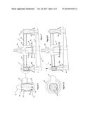
[0036] Extending laterally from the central portion of the structure 2 are lateral arms 11 each of which supports a tubular receptacle 12 each of which corresponds to one of the guide posts and is positioned to receive the respective guide posts as the structure 2 is lowered towards the structure 1. The receptacles are all similar and only the left-hand receptacle 12a in FIG. 7 will be described mainly with reference to FIG. 8, which illustrates to a larger scale the detail within the circle Y in FIG. 7.
[0037] The receptacle 12a has a straight tubular portion 13 of constant cross section and an outwardly flared lower rim 14 (FIG. 10). This receptacle constitutes a docking cone which facilitates initial engagement of the receptacle and post when as usual they are not initially axially aligned. On the post 4 are disposed semi-elliptical springs 15. There may be two opposed springs but preferably as shown there are four springs in two orthogonal pairs. Each spring is disposed lengthwise relative to the post and the receptacle 13. It is fixed to the post 4 near the top thereof by a foot 19 at its upper end. At its other end 20 the spring has a foot 20 which is supported by a screw 21 which extends through a respective hole in the end 20. The screw is adjustable to move the foot 20 radially with respect to the post and may be secures by a nut 22. The screw allows movement of the lower end of the spring 15 relative to the tubular portion 13.
[0038] The springs on each post engage slidingly the inner surface of the tubular part 13 of the respective receptacle 12 and provide an automatic centering action. For this purpose the springs should be substantially similar in shape and spring rate. In this example the centering action is along two axes normal to the axis of the post 4.
[0039] FIGS. 7 and 8 illustrate the structures 1 and 2 when they have been mutually engaged correctly.
[0040] FIG. 9 illustrates the structures when as will frequently occur there is obliquity in the approach of the structures as indicated by the curved arrow B. FIG. 10 is a plan view on arrow A of the receptacle 12a and its post in this condition. The obliquity can be accommodated by the springs and corrected to leave the structures in the positions shown in FIG. 7.
User Contributions:
Comment about this patent or add new information about this topic:
Images included with this patent application:
 |  |
 |  |
| New patent applications in this class: | |
| Date | Title |
|---|---|
| 2015-11-19 | Decommissioning offshore oil and gas wells |
| 2015-05-14 | Position monitoring for subsea bellow compensators |
| 2015-03-19 | Method for handling a hydro sound absorber, and device for reducing underwater noise |
| 2015-02-26 | Structures for offshore installations |
| 2015-01-08 | Mooring structure with habitat features for marine animals |
| Top Inventors for class "Hydraulic and earth engineering" | |
| Rank | Inventor's name |
|---|---|
| 1 | Joop Roodenburg |
| 2 | Thomas P. Taylor |
| 3 | Michael Tjader |
| 4 | Keith K. Millheim |
| 5 | John G. Oldsen |