Patent application title: ANNULAR FLUID CONTAINMENT DEVICE
Inventors:
Gerald Bullard (Alliance, NE, US)
IPC8 Class: AE21B3300FI
USPC Class:
166101
Class name: Wells packer or plug and pump or plunger means exerting outward pressure
Publication date: 2014-11-20
Patent application number: 20140338887
Abstract:
An annular fluid containment device includes a mandrel, and packing
assembly disposed about the mandrel to form a seal between the mandrel
and the well casing. A sleeve disposed within the mandrel defines a space
between the mandrel and the sleeve. Seals are disposed between the
mandrel and sleeve at upper and lower ends, wherein the upper seal is
located above a location of the packing assembly, and the lower seal is
located below the packing assembly. Upper and lower passages are defined
in the wall of the mandrel, in communication with the annular space,
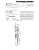
wherein the upper fluid passage is located above the packing assembly and
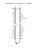
below the upper seal, while the lower fluid is located below the position
of the packing assembly and above the lower seal. Hence, a fluid passage
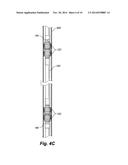
is formed bypassing the packing assembly within the mandrel.Claims:
1. An annular fluid containment device adapted for placement into a well
casing, comprising: a tubular main body having an outer surface, an inner
surface, and upper and lower ends; at least one sealing assembly disposed
about said main body and adapted to form a seal between the outer surface
of said main body and an inner wall surface of said well casing; a
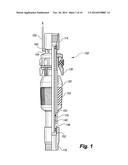
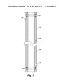
tubular inner sleeve disposed within said main body, the inner sleeve
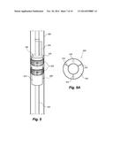
having an outer surface, an inner surface, and upper and lower ends,
wherein the outer surface of the inner sleeve is spaced apart from the
inner surface of the main body to define an annular space therebetween;
at least one upper seal disposed between the inner surface of the main
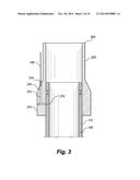
body and the outer surface of the inner sleeve proximate to the upper end
of the inner sleeve and above a location of said sealing assembly; at
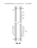
least one lower seal disposed between the inner surface of the main body
and the outer surface of the inner sleeve proximate to the lower end of
the inner sleeve and below the location of said sealing assembly; an
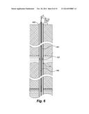
upper fluid passage defined through said main body in communication with
said annular space, the upper fluid passage being located above the
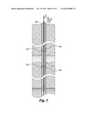
position of said sealing assembly and below said upper seal; and a lower
fluid passage defined through said main body in communication with said
passage, the lower fluid passage being located below the position of said
sealing assembly and above said lower seal.
2. The annular fluid containment device of claim 1, further comprising a fluid conduit connected to and extending from said upper fluid passage.
3. The annular fluid containment device of claim 1, wherein said at least one sealing assembly comprises a rubber seal.
4. The annular fluid containment device of claim 1, wherein said at least one sealing assembly comprises a plurality of rubber seals.
5. The annular fluid containment device of claim 1, further comprising an upper collar disposed at an upper end of said main body, the upper collar being configured for connection to a production tubing element.
6. The annular fluid containment device of claim 5, wherein a gas passage is formed in said upper collar in communication with said upper fluid passage.
7. The annular fluid containment device of claim 5, further comprising a lower collar disposed at an upper end of said main body, the lower collar being configured for connection to a production tubing element.
8. The annular fluid containment device of claim 1, wherein said at least one sealing assembly comprises at least one upper sealing assembly disposed proximate to the upper end of said main body, and at least one lower sealing element disposed proximate to the lower end of said main body.
9. The annular fluid containment device of claim 6, further comprising a fitting in communication with said gas passage and configured for connection to a tubing.
Description:
FIELD OF THE INVENTION
[0001] The present invention relates to apparatus for repairing a damaged well casing, and more particularly to a method and apparatus for inexpensively repairing a producing well.
BACKGROUND
[0002] In the well servicing industry, a common problem encountered is a damaged well casing in a well. It is desirable to quickly and inexpensively repair a damaged well casing. In particular, in a marginally producing well, a quick and inexpensive method is desirable such that the well may be maintained in production in a cost effective manner.
[0003] In a typical gas or oil well, for example, a well casing is placed within a bore hole such that the well casing extends from the surface to the production zone. A production tubing string is placed within the casing, and the gas or oil is withdrawn through the production string. An annular space, or annulus, surrounds the production string, between the exterior wall of the production string and the interior wall of the well casing.
[0004] During the life of the well, the casing may become corroded or otherwise damaged, resulting in holes or openings in the casing which allow water or other undesirable fluids to enter into the annular space between the production string and well casing, and travel downward to reach the production zone. Accumulation of the undesirable fluids within the annular space may result in reduced production, either by inhibiting the free flow of gas or oil into the production zone and into the production tubing, or simply by displacing a substantial quantity of the gas or oil such that pumping operations must pump a large quantity of the undesirable fluid along with a desired product of the well, reducing the efficiency of recovery of the well.
[0005] For example, in an oil well, the well casing may pass through a water-bearing sand formation well above an oil formation from which oil is pumped. Corrosion of the well casing such as by the water in the water-bearing sand formation may result in holes, cracks or other openings in the well casing, allowing entry of the water into the well casing. Once entered into the annular space within the well casing, the water will travel to the bottom of the well to the oil formation. Accumulation of excessive water may result in hydrostatic pressure sufficient to prevent entry of oil into the casing, or may simply mix with oil such that a diminished quantity of oil is recovered as the water is pumped up along with the oil. In either case, it is desirable to prevent water, or other undesirable fluids, from reaching the production zone.
[0006] It is therefore desirable to introduce a sealing device into the annular space, below the damaged portion of the casing and above the production zone, forming a seal against the casing to prevent undesirable fluids entering the casing from reaching the production zone.
[0007] A variety of sealing devices are known, including packers such as tension packers, compression packers and the like, which include, broadly speaking, a mandrel or tubing forming essentially a core of the packer, a packing element disposed about the mandrel to provide a seal against the inside wall of the casing, a set of slips for gripping against the casing wall, and a mechanism to set (and, in some arrangements, a mechanism to release) the packer.
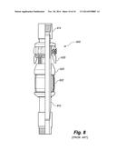
[0008] A conventional tension packer 600 is shown in FIG. 8, including a main body or mandrel 610, a packing element 620 and an assembly of slips 630. The packing element 620 of the illustrated packer includes, inter alia, a packer rubber 622 disposed between upper and lower retainers, and provides a sealing function by forming a seal between the main body 610 and in inner wall of a well casing when the packer 600 is set within the well casing. Commonly, an upper collar 614 and lower collar 616 are provided for connection of the packer within a tubing string. A setting process causes outward expansion of the packing rubber 622 to press the packing rubber 622 against the interior wall of a well casing, forming a seal in the annulus between the casing and tubing string. At the same time, the slips 630 extend outward to grip against the casing, assisting in holding the packer in place.
[0009] However, introduction of a seal into the annular space may result in problem in that pressure from the oil formation may build up within the annulus below the sealing device. In certain circumstances, such pressure may build to a point wherein, because of the pressure build up, the well's production is reduced or stopped altogether. That is, as pressure within the casing or the annular space between the casing and the production string increases, the tendency for oil to flow into the casing decreases. Therefore, it is desirable, in a sealing device provided in the annular space as discussed above, to include a venting means for venting and releasing pressure through the sealing device, while preventing water, or other undesirable fluids, from reaching the production zone.
[0010] Another problem found in the use of retrievable sealing devices such as conventional retrievable well packers is that accumulation of debris above within the annular space and above sealing element may hinder retrieval of the sealing device. That is, once such a sealing device is set, any debris introduced into the annular space, such as sand or silt brought into the annular space along with an undesirable fluid through a breach or opening in the casing simply collects on top of the sealing device, and over time may collect to a degree such that the presence and amount of the debris causes difficulty in removal of the sealing device.
SUMMARY
[0011] An retrievable annular fluid containment device and method are provided for introducing a seal into the annular space between a well casing and a tubing string within the casing, providing a venting means for venting and releasing pressure through the seal to eliminate a pressure differential within the annulus across the seal.
[0012] According to one aspect of the invention, an annular fluid containment device comprises a tubular main body tubing having an outside diameter configured for placement within a well casing to define an annular space between an outside wall of the tubing and an inside wall of the well casing. A packing element is disposed about the main body and is configured for forming a seal between the main body and an inside wall of the well casing. A tubular inner sleeve is disposed within the main body, with an outer surface of the inner sleeve spaced apart from an inner surface of the main body to define an annular passage therebetween. Upper and lower seals are provided between the main body and the inner sleeve, at upper and lower ends of the inner sleeve respectively, to enclose ends of the annular passage. An upper gas or fluid port is formed through the wall of the main body near the upper end of the inner sleeve, and above a position of the packing element, and a lower gas or fluid port is formed through the wall of the main body near the lower end of the inner sleeve, and below a position of the packing element. Hence, a gas or fluid conduit is formed within the main body, bypassing the packing element, allowing equalization of pressures within the annulus below and above the packing element, once the annular fluid containment device is placed and set within a well casing.
[0013] In another aspect of the invention, fittings may be provided at one or both of the gas or fluid ports for attachment of a tubing or hose, for example to allow connection of a tubing or hose to the upper gas or fluid port to allow venting to the surface or to a position within the well above the height of any accumulated water or undesirable fluid entered into the annulus.
[0014] According to a further aspect of the invention, a rupture disk or other pressure releasing element may be provided in, or in conjunction with, the annular fluid containment device, preferably above the packing element, to allow a flushing operation by introducing water or another fluid into the production string, and pressurizing the water or other fluid to cause bursting of the rupture disk, whereupon the water or other fluid is emitted through an aperture formed by the burst rupture disk, for example to flush debris accumulated above the packing element.
[0015] These and other features, aspects, and advantages of the present invention will become better understood with regard to the following description, appended claims, and accompanying drawings.
BRIEF DESCRIPTION OF THE DRAWINGS
[0016] FIG. 1 is a side view of an annular fluid containment device embodied as a tension packer.
[0017] FIG. 2 is a cross-section view of a mandrel and inner sleeve of the annular fluid containment device of FIG. 1.
[0018] FIG. 3 cross-section view of an upper end of the annular fluid containment device of FIG. 1.
[0019] FIG. 4A is a cross-section view of an annular fluid containment device having an alternative arrangement of water seals disposed on the mandrel.
[0020] FIG. 4B is a cross-section view of an annular fluid containment device having a further alternative arrangement of water seals disposed on the mandrel.
[0021] FIG. 4C is a side view of an annular fluid containment device having a still further alternative arrangement of water seals disposed on the mandrel.
[0022] FIG. 5 is a side view of a further embodiment of an annular fluid containment device.
[0023] FIG. 5A is a bottom view of the embodiment of FIG. 5.
[0024] FIG. 6 is a diagrammatic view showing placement of an annular fluid containment device within a well casing.
[0025] FIG. 7 is a diagrammatic view showing placement of an annular fluid containment device within a well casing.
[0026] FIG. 8 is a side view of a conventional tension packer.
DETAILED DESCRIPTION OF VARIOUS EMBODIMENTS
[0027] Referring to FIG. 1, an annular fluid containment device 100 according to one embodiment comprises a mandrel 110, packing element 120 including packing rubber or sealing element 122, and slips 130 arranged in a generally conventional manner. In particular, in this embodiment the mandrel 110 is configured to be included in a production tubing string in a known manner, wherein an upper collar 114 and lower collar 116 are provided at upward and lower ends of the mandrel 110, and are configured for connection of the mandrel within the production tubing string. According to the present invention, an inner sleeve 140 is disposed within the mandrel 110 to form a fluid passage way 150 from a point below the packing element 120 to a point above the packing element 120.
[0028] Turning to FIG. 2, which shows the mandrel 110 without the packing element 120, slips 130 and collars 114, 116 for clarity, the mandrel 110 is, conventionally, a length of tubing having a tubing wall defining a hollow interior. The mandrel 110 has an inner diameter and an outer diameter suitable for compatibility with a well production tubing string. The inner sleeve 140 is disposed within the mandrel 110, and has an outer diameter smaller than the inner diameter of the mandrel 110. Hence, a space is formed between an outside wall surface 142 of the inner sleeve 140 and an inside wall surface 112 of the mandrel 110.
[0029] Upper and lower seals are provided between the outside wall surface 142 of the inner sleeve 140 and the inside wall of the mandrel 110, proximate to the upper and lower ends of the mandrel 110 respectively. In the illustrated embodiment, each seal is formed by one or more O rings 152, seated in seating grooves 148 formed in the outside wall surface 142 of the inner sleeve 140.
[0030] An upper gas port 144 is formed through the mandrel wall at a point above the lower seals and below the packing element 120, allowing fluid communication between outside of the mandrel 110 and the fluid passage way 150 between the inner sleeve 140 and the mandrel 110. Similarly, a lower gas port 146 is formed through the mandrel wall at a point below the upper seals and above the packing element 120, allowing fluid communication between outside of the mandrel 110 and the fluid passage way 150 between the inner sleeve 140 and the mandrel 110. Hence, in practice, when the annular fluid containment device 100 is set within a well casing, a passage is provided to equalize pressures within the annulus below and above the packing element 120, such as to vent a gas produced in a well formation below the annular fluid containment device 100 to a point above the annular fluid containment device 100 in order to equalize a gas pressure across the annular fluid containment device 100.
[0031] The upper gas port 144 and lower gas port 146 can be formed simply as an open aperture 158 through the mandrel 110 wall. More preferably for certain applications, the upper gas port 144 and lower gas port 146 may be provided with a fitting 154 for connection to a venting tubing or hose 156 or the like to extend fluid entry or exit positions to points well above, or well below, the annular fluid containment device 100. For example, a length of tubing or hose may be fitted to the upper gas port 144 and extended to the well surface, to vent a well gas fully to the surface of the well. Alternatively, such a length of tubing or hose may be provided to locate an upward vent exit above the height of expected fluid acumination in the well's annulus, to avoid passage of such fluid downward below the annular fluid containment device 100.
[0032] Turning to FIG. 3, in an illustrated embodiment an upper collar 300 may be formed with a manifold portion 310 which is internally threaded for attachment to the upper end of the mandrel 110, and a mating portion 320 extending from the manifold portion 310 configured for attachment to a next production tubing element in a tubing string. The manifold portion 310 comprises a thicker wall than the mating portion 320, the outside diameter of the upper collar 300 decreasing in transition from the manifold portion to the mating portion 320. A passage 312 is formed within the manifold portion 310, and is arranged in communication with the upper gas port 144 of the mandrel. The passage 312 may be formed to extend upward (in an axial direction) along or within the manifold portion 310, preferably exiting the manifold portion 310 in a transition region between the manifold portion 310 and the mating portion 320, to allow for connection of the tubing or hose 156 in a manner extending alongside the mating portion 320. More particularly, the passage 312 may be formed by drilling a first hole 314 through the manifold portion 310 wall and through the wall of the mandrel 110 (these holes may be drilled together, in a single step or separately and arranged for alignment upon assembly of the upper collar 114 to the mandrel 110), and drilling a second hole 316 in a longitudinal direction within the manifold portion wall, the second hole 316 intersecting the first hole 314 to form a continuous passage leading from the fluid passage way 150 to outside of the upper collar 114, and the first hole 314 plugged to provide the passage 312 as a single path in communication from the upper gas port 144 of the mandrel 110. Fitting 154 and tubing or hose 156 may be arranged to extend from the manifold portion 310 generally in parallel alongside the mating portion 320 of the upper collar 114, so that the tubing or hose 156 may be easily run alongside a tubing string above the annular fluid containment device 100.
[0033] Returning to FIG. 1, some embodiments of the annular fluid containment device 100 may include a rupture disk 160 or other pressure releasing element provided in the wall of the mandrel 110 or at another position above the packing element 120. The rupture disk 160 is adapted to burst upon application of a predetermined fluid pressure within the mandrel 110 (and, more broadly speaking, within the production tubing string). In practice, the rupture disk 160 may be used for flushing accumulated mud, dirt or sand from above the annular fluid containment device 100. For example, if it is desired to pull the production tubing and annular fluid containment device 100 from a well, it may be necessary or desirable to flush debris away from the top of the annular fluid containment device 100 prior to pulling the tubing. In one such operation, pumping rods and a pump are removed from the well, and then a standing valve downtubing is dropped into the well and into the seating nipple at the well bottom. The tubing may be filled with water from the surface, and then pressurized to burst the rupture disk 160, allowing the water to exit the mandrel through an aperture formed by the bursted rupture disk, flushing debris from the top of the annular fluid containment device 100.
[0034] Turning to FIGS. 4A and 4B, embodiments of the annular fluid containment device are shown employing differently arranged packing elements. In an embodiment shown in FIG. 4A, an annular fluid containment device 100 includes a packing element embodied as a simple water sealing element 122, rather than the tension-settable packing element 120 of the embodiment of FIG. 1. Such an embodiment of the annular fluid containment device 100 may be located in a well casing by simply sliding the annular fluid containment device 100 into place, without further need for mechanical manipulation or "setting" of the device as in a tension-packer based embodiment. That is, in such embodiments the water sealing elements 122 are simply annular water seals (such as rubber seals, water cups or gaskets or the like), which are sized to fit snugly against the inside wall of the well casing, while allowing for the annular fluid containment device 100 to slide lengthwise within the well casing for placement. Further, turning to FIG. 4B, more than a single water sealing element 122 may be used. In an embodiment shown in FIG. 4B, a second water sealing element 122 may be located on the mandrel 110 at some distance away from a first water sealing element 122, for example such that the water sealing elements 122 may span a breach, or area of breach or damage, in the well casing. Such an arrangement is describe in further detail below. Additionally, multiple water sealing elements 122 may be closely spaced together simply to form a greater fluid seal. Referring to FIG. 4C, an embodiment is shown, placed within a well casing 400, comprising a set of lower water sealing elements 122 located near a bottom end of the mandrel 110, and a set of upper water sealing elements 122 located near a top end of the mandrel 110. An upper gas port 144 and a lower gas port 146 are found respectively located above the upper water sealing elements 122 and below the lower water sealing elements 122, providing for fluid or gas pressure equalization between the annular regions above and below the annular fluid containment device 100.
[0035] Turning to FIGS. 5 and 5A, another embodiment of an annular fluid containment device 500 is shown. Relative to the previous embodiments, and relative to the conventional tension packer, the embodiment of FIG. 5 comprises a tubular mandrel 510 through which a production tubing segment 512 is run, generally centered within the mandrel 510. That is, whereas in the previous embodiments the mandrel can be considered as a segment of a production tubing string, in the embodiment of FIGS. 5 and 5A the mandrel 510 is disposed outside of a segment of the production tubing string, such that a venting/bypass space is formed outside, rather than inside, of the production tubing segment.
[0036] In the illustrated embodiment, steel rods or standoffs 514 are provided for centering the production tubing segment 512 within the mandrel 510. A top plate 516 encloses the top end of the mandrel, and includes a venting aperture or port 518. The bottom of the mandrel 510 may be similarly closed by a plate having a venting aperture, or may be simply left open. As in the embodiments of FIGS. 2B and 2C, an annular fluid containment device 500 of this embodiment is provided with rubber seals 522 surrounding the mandrel 510 which may be simply slid into place as the annular fluid containment device 500 is placed into the well casing 400. That is, the rubber seals 522 are configured having an outer diameter slightly greater than the inside diameter of the well casing 400, and are of a somewhat resilient or pliant nature such that the annular fluid containment device 500 is simply slid into the well casing 400, with the rubber seals 522 in sealing contact with the inner wall of the well casing 400, until the annular fluid containment device 500 reaches a desired position in the well. As in the previous embodiments, a rupture disk 160 may be provided, for example disposed in the top plate 516 as shown in the figure.
[0037] An arrangement of a packer an annular fluid containment device 100 within a well is shown in FIG. 6. In a production arrangement, a production tubing string extends from the surface downward through the well bore and well casing to a pump placed in the well's production zone. A pump rod extends within the production tubing string to drive the pump. In the arrangement of FIG. 6, an annular containment device 100 is incorporated into the production tubing string, and is positioned below a breach in the casing, such as a hole or damage due to corrosion of the casing, cross-threading between casing collars or another type of breach allowing entry of a fluid such as water into the annular space between the well casing and production tubing.
[0038] The packing element 120 of the annular fluid containment device 100 forms a seal to contain the fluid entering into the annular space above the annular fluid containment device 100. Hence, the fluid is prevented from reaching the production zone below the annular fluid containment device 100. At the same time, the venting provided by the annular fluid containment device 100 allows for equalization of gas pressure above and below the annular fluid containment device 100, preventing gas pressure from building below the annular fluid containment device 100 to an undesirable level. A hose or tubing can be connected to the upper gas port 144, and extended to the surface, or to a point above the height of expected fluid accumulation above the annular fluid containment device 100, to prevent the accumulated fluid above the annular fluid containment device 100 from flowing through the gas bypass of the annular fluid containment device 100 and into the production zone below the annular fluid containment device 100.
[0039] Referring to FIG. 7, placement of an embodiment of an annular fluid containment device 100 having upper and lower sealing elements 122. The upper and lower sealing elements 122 are spaced apart on the mandrel 110 such that, when placed within the well casing, the upper and lower sealing elements 122 are positioned respectively above and below a breach in the well casing. Hence, water or a fluid entering the annular space between the production tubing string and the well casing through the breach is contained within the annular space bounded by the upper and lower sealing elements 122. Again, the venting provided by the annular fluid containment device 100 allows for equalization of gas pressure above and below the annular fluid containment device 100.
[0040] It will be understood that the above-described embodiments of the invention are illustrative in nature, and that modifications thereof may occur to those skilled in the art. Accordingly, this invention is not to be regarded as limited to the embodiments disclosed herein, but is to be limited only as defined in the appended claims.
User Contributions:
Comment about this patent or add new information about this topic:
Images included with this patent application:
 |  |
 |  |
 |  |
 |  |
 |  |
 |
| Similar patent applications: | |
| Date | Title |
|---|---|
| 2014-09-18 | Annular blowout container (aboc) |
| 2014-12-04 | Annular barrier with a self-actuated device |
| 2014-10-23 | Fluid container reloading tool |
| 2014-12-04 | Controlling bioavailability of nutrient additions in subsurface formations |
| 2014-12-04 | Ampholyte polymeric compounds in subterranean applications |
| New patent applications in this class: | |
| Date | Title |
|---|---|
| 2014-09-25 | Expandable packer |
| 2014-08-28 | Downhole seal element and related apparatuses |
| 2013-05-30 | Seat assembly for isolating fracture zones in a well |
| 2013-03-14 | Shaped memory polyphenylene sulfide (pps) for downhole packer applications |
| 2012-09-06 | Coiled tubing deployed esp |
| New patent applications from these inventors: | |
| Date | Title |
|---|---|
| 2012-11-15 | Annular fluid containment device |
| 2009-07-09 | Bridge plug and setting tool |
| Top Inventors for class "Wells" | |
| Rank | Inventor's name |
|---|---|
| 1 | Michael L. Fripp |
| 2 | Jean Marc Lopez |
| 3 | Michael H. Johnson |
| 4 | Jørgen Hallundbaek |
| 5 | Dennis P. Nguyen |