Patent application title: CABLE FOLDING DEVICE
Inventors:
Guang Yang (Shenzhen, CN)
Guang Yang (Shenzhen, CN)
Assignees:
HON HAI PRECISION INDUSTRY CO., LTD.
FU TAI HUA INDUSTRY (SHENZHEN) CO., LTD.
IPC8 Class: AB21F100FI
USPC Class:
723905
Class name: With tool motion in fixed path between and co-planar with opposed tools lever actuated
Publication date: 2014-10-30
Patent application number: 20140318207
Abstract:
A cable folding device includes a base, a push element slidably connected
to the base, and an elastic element connected between the base and the
push element. One end of the base is curved to form two parallel position
pins used to engage a cable. The push element includes a push sheet set
on one end. The push sheet is aligned with a space between the two
position pins. The push sheet is pushed by an external force to move
towards the cable until the push sheet folds the cable between the two
position pins. The elastic element is recoiled to drive the push sheet to
return to an original position.Claims:
1. A cable folding device comprising: a base, wherein one end of the base
is curved forming two parallel position pins which is used to engage a
cable; a push element slidably connected to the base, and comprising a
push sheet set on one end thereof, wherein the push sheet is aligned with
a space between the two position pins; and an elastic element connected
between the base and the push sheet; wherein the push sheet is pushed by
an external force to move towards the cable until the cable between the
two position pins is folded by the push sheet, the elastic element is
recoiled to drive the push sheet to return to an original position.
2. The cable folding device as described in claim 1, wherein the base comprises a fixing pole and a plurality of fixing blocks spaced at intervals on the fixing pole, each of fixing block defines a perforation aligned with the space between the two position pins along a lengthwise direction of the fixing pole, the push element passes through the perforation to slidably connect to the base.
3. The cable folding device as described in claim 2, further comprising a trigger element rotatably connected to the base, wherein the trigger element comprises a trigger portion aligned with the push element and a pull portion fixed to the trigger portion.
4. The cable folding device as described in claim 3, wherein the base further comprises a handle fixed below the fixing pole, the handle comprises a first grip portion fixed to the fixing pole and a second grip portion fixed to the first grip portion, the first grip portion defines a first hole, the second grip portion defines a second hole aligned with the first hole, the trigger element defines a third hole aligned with the first hole and the second hole, the cable folding device further comprises a pivot shaft, the pivot shaft passes through the second hole, the third hole and the first hole to rotatably connect the trigger element between the first grip portion and the second grip portion.
5. The cable folding device as described in claim 2, wherein one end of the fixing pole away from the position pins comprises a first hooking portion, one end of the push element away from the push sheet comprises a second hooking portion, the elastic element is connected between the first hooking portion and the second hooking portion.
6. The cable folding device as described in claim 1, wherein the elastic element is a spring.
7. The cable folding device as described in claim 5, wherein one end of the push element adjacent to the second hooking portion downwardly extends to form a limiting portion aligned with the trigger portion.
Description:
FIELD
[0001] The present disclosure relates to folding devices, and particularly to a cable folding device.
BACKGROUND
[0002] In prior art, when assembling an electronic device, it is needed to manually fold a cable connected between a display and a main body to a M shape before assembling the display on the main body. If the cable cannot be folded in the M shape, the display may not be level on the main body. However, due to the limitation of size and material being used in the manufacturing of the cable, it is difficult to fold the cable manually to the M shape.
BRIEF DESCRIPTION OF THE DRAWING
[0003] FIG. 1 is an isometric view of a cable folding device, in accordance with an exemplary embodiment.
[0004] FIG. 2 is an exploded view of the cable folding device of FIG. 1.
[0005] FIG. 3 is an isometric view of the cable folding device of FIG. 1 in a working state.
DETAILED DESCRIPTION
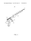
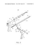
[0006] FIG. 1-2 show an embodiment of a cable folding device 100. The cable folding device 100 includes a base 10, a push element 20, a trigger element 30, a pivot shaft 40, and an elastic element 50.
[0007] The base 10 includes a fixing pole 11 and a handle 12 fixed below the fixing pole 11. One end of the fixing pole 11 is curved forming two parallel position pins 13, a first hooking portion 14 is formed on another end of the fixing pole 11. The base 10 further includes a number of fixing blocks 15 spaced at intervals on the fixing pole 11. Each fixing block 15 defines a perforation 150 aligned with a space between two parallel position pins 13 along a lengthwise direction of the fixing pole 11. The handle 12 includes a first grip portion 16 fixed to the fixing pole 11 and a second grip portion 17 fixed to the first grip portion 16. The first grip portion 16 defines a first hole 160. The second grip portion 17 defines a second hole 170 aligned with the first hole 160.
[0008] The push element 20 passes through the perforation 150 to slidably connect to the fixing pole 11. One end of the push element 20 is formed into a push sheet 21, and another end of the push element 20 is formed into a second hooking portion 22. The end of the push element 20 adjacent to the second hooking portion 22 downwardly extends to form a limiting portion 23 aligned with the fixing block 15.
[0009] The trigger element 30 is rotatably connected between the first grip portion 16 and the second grip portion 17. The trigger element 30 includes a trigger portion 32 aligned with the limiting portion 23 and a pull portion 33 fixed to the trigger portion 32. A third hole 31 is defined in the trigger element 30 aligning with the first hole 160 and the second hole 170. The pivot shaft 40 passes through the second hole 170, the third hole 31 and the first hole 160 to rotatably connect the trigger element 30 between the first grip portion 16 and the second grip portion 17.
[0010] The elastic element 50 is connected between the first hooking portion 14 and the second hooking portion 22. In one embodiment, the elastic element 50 is a spring.
[0011] When assembling the cable folding device 100, the push element 20 passes through the perforations 150 to slidably connect the fixing pole 11, the elastic element 50 is connected between the first hooking portion 14 and the second hooking portion 22. The pivot shaft 40 passes through the second hole 170, the third hole 31 and the first hole 160 to rotatably connect with the trigger element 30 between the first grip portion 16 and the second grip portion 17.
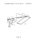
[0012] FIG. 3 shows that when using the cable folding device 100, a display 300 is placed slanted towards a main body 400, a cable 200 is connected between the display 300 and the main body 400. Next, the two parallel position pins 13 engage the cable 200 between the display 300 and the main body 400. The trigger portion 32 is driven by the manual action applied to the pull portion 33, pushing the limiting portion 23 until the limiting portion 23 is resisted by the fixing block 15. During the process of pushing the limiting portion 23, the push sheet 21 is driven to move towards the space between the two position pins 13 until the cable 200 is folded to a M shape by the push sheet 21, the elastic element 50 is stretched by the push element 20. After the external force is released, the elastic element 50 rebounds to drive the push element 20 to return to an original position.
[0013] Although various embodiments have been specifically described, the disclosure is not to be construed as being limited thereto. Various changes or modifications may be made to the embodiments without departing from the scope and spirit of the disclosure.
User Contributions:
Comment about this patent or add new information about this topic:
Images included with this patent application:
 |  |
 |  |
| Similar patent applications: | |
| Date | Title |
|---|---|
| 2014-11-06 | Die for a punching device |
| 2014-11-20 | Industrial machine for bending metallic flat elements |
| 2010-12-09 | Bending device |
| 2012-01-12 | Bending device |
| 2013-03-28 | Levelling device |
| New patent applications from these inventors: | |
| Date | Title |
|---|---|
| 2022-09-15 | Portable blowing device |
| 2022-07-28 | Portable blowing device |
| 2021-11-18 | Portable blowing device |
| 2021-11-18 | Portable blowing device |
| 2018-06-07 | Method and apparatus for switching real-time image in instant messaging |
| Top Inventors for class "Metal deforming" | |
| Rank | Inventor's name |
|---|---|
| 1 | Sergey Fedorovich Golovashchenko |
| 2 | Joel T. Pyper |
| 3 | Scott M. Breen |
| 4 | Thomas Flehmig |
| 5 | Matthias Kipping |