Patent application title: RENEWAL ENERGY POWER GENERATION SYSTEM
Inventors:
Colin Salmond (Beerwah, AU)
Grant Salmond (Mt Isa, AU)
Assignees:
ELECTRYGEN PTY LTD
IPC8 Class: AH01M806FI
USPC Class:
320101
Class name: Electricity: battery or capacitor charging or discharging wind, solar, thermal, or fuel-cell source
Publication date: 2014-10-16
Patent application number: 20140306645
Abstract:
Provided is a renewable energy power generation system (10) having a
renewable energy power generating apparatus (12) arranged to generate
electric power; and a hydrogen power generation module (20) having a
separation unit (22) adapted to separate water into hydrogen and oxygen,
and a fuel cell unit (28) adapted to receive air or oxygen, and hydrogen
from said separation unit or from a hydrogen storage; the fuel cell unit
being arranged to produce electric power in the presence of hydrogen and
oxygen; wherein the hydrogen power generation module being adapted to
receive electric power from the at least one renewable energy power
generating apparatus at least prior to production of electric power by
the fuel cell unit.Claims:
1. A renewable energy power generation system comprising at least one
renewable energy power generating apparatus adapted to generate electric
power; and a hydrogen power generation module having a separation unit
adapted to separate water into hydrogen and oxygen, and a fuel cell unit
adapted to receive air or oxygen, and hydrogen from said separation unit
or from a hydrogen storage; the fuel cell unit being arranged to produce
electric power in the presence of hydrogen and oxygen; wherein the
hydrogen power generation module being adapted to receive electric power
from the at least one renewable energy power generating apparatus at
least prior to production of electric power by the fuel cell unit.
2. The system according to claim 1 wherein the at least one renewable energy power generating apparatus is adapted to use one or a combination of two or more renewable energy sources to generate electric power.
3. The system according to claim 2 wherein the renewable energy sources include wind, solar, water, wave, geothermal and the like energy sources.
4. The system according to claim 1 further having one or more electric power storage devices adapted to store the electric power from the at least one renewable energy power generating apparatus and the hydrogen power generation module.
5. The system according to claim 4 wherein the storage devices include batteries and/or capacitors.
6. The system according to claim 1 further having conversion means adapted to covert the electric power to a form suitable for powering domestic and/or industrial electric appliances and/or equipment.
7. The system according to claim 1 further having a water purification module adapted to provide a relatively pure water from a water source.
8. The system according to claim 6 wherein the water source is derived from sea water, brackish water, or any water containing part of land such as river or lake or dam.
9. The system according to claim 7 wherein the system is adapted to covey a part of the water from the water purification module for use domestically or industrially.
10. The system according to claim 7 wherein said fuel cell unit is adapted to produce water at an elevated temperature.
11. The system according to claim 10 wherein the water from the fuel cell unit is arranged to be conveyed to an air conditioning system for exchanging heat with a working fluid of the air conditioning system.
12. The system according to claim 7 further having has a water tank adapted to hold water from the water purification module and at least a part of the water from the fuel cell unit, and mineralization means adapted to add appropriate minerals to water from the water tank so as to be potable.
13. The system according to claim 1 being adapted to control the harvest and delivery of sustainable energy from the sun, PVC (photo voltaic cells) and heat, wind, hydro, geothermal steam generation and additionally to capture hydrogen energy from water electrolysis, waste and anaerobic sources in order to supply stationary commercial/domestic base load MWs and mobile electric motors/propulsors.
14. The system according to claim 1 wherein the product hydrogen is arranged to be stored in a safe hydrogen storage by cryogenic, metal hydride and chemical hydride means, thereby delivering improved Hydrogen Fuel Cell efficiencies.
15. The system according to claim 1 further having a controller adapted to control operation of said at least one renewable energy power generating apparatus, and/or the hydrogen power generation module, and/or one or more electric power storage devices, and/or said conversion means.
16. The system according to claim 2 further having one or more electric power storage devices adapted to store the electric power from the at least one renewable energy power generating apparatus and the hydrogen power generation module.
17. The system according to claim 3 further having one or more electric power storage devices adapted to store the electric power from the at least one renewable energy power generating apparatus and the hydrogen power generation module.
18. The system according to claim 2 further having conversion means adapted to covert the electric power to a form suitable for powering domestic and/or industrial electric appliances and/or equipment.
19. The system according to claim 3 further having conversion means adapted to covert the electric power to a form suitable for powering domestic and/or industrial electric appliances and/or equipment.
20. The system according to claim 4 further having conversion means adapted to covert the electric power to a form suitable for powering domestic and/or industrial electric appliances and/or equipment.
Description:
TECHNICAL FIELD
[0001] THIS INVENTION relates to a renewable energy power generation system, and in particular but not limited thereto, the system is adapted to use at least one renewable energy source and a hydrogen fuel source to provide power for propulsion delivery for both stationary and mobile applications on land, sea and in space.
BACKGROUND
[0002] The GDP growth aspirations and expectations of the world population are in collision with peak oil' and man accelerated global warming. These events have resulted from a century of fossil-fuelled greenhouse gas emissions, largely caused by consumption of coal/oil/gas. Sustainable energy is between a rock and a hard place. This impasse is the catalyst to create sustainable, renewable energy fuels from the most abundant free sources, sun, wind, moon, water, earth's plasma. It is desirable to control the harvest, storage and delivery of this abundant/natural/free energy at a relatively low cost per MW in the face of unsustainable fossil-fuelled energy.
[0003] Coal, oil and gas fired power stations have historically provided commercial & domestic base load energy from mining earth's fossil reserves. Crude oil/gas products have fuelled the transport industry through the ICE plant (internal combustion engine) which is a highly matured/sophisticated device but low in efficiency, in the order of 20%. World distribution infrastructures of fossil fuel are widespread.
OBJECT OF THE INVENTION
[0004] It is an object of the present invention to provide a hydrogen power generation system to alleviate or to at least reduce to a certain level one or more of the prior art disadvantages
SUMMARY OF THE INVENTION
[0005] In one aspect therefore the present invention resides in a renewable energy power generation system comprising at least one renewable energy power generating apparatus adapted to generate electric power; and a hydrogen power generation module having a separation unit adapted to separate water into hydrogen and oxygen, and a fuel cell unit adapted to receive air or oxygen, and hydrogen from said separation unit or from a hydrogen storage; the fuel cell unit being arranged to produce electric power in the presence of hydrogen and oxygen; wherein the hydrogen power generation module being adapted to receive electric power from the at least one renewable energy power generating apparatus at least prior to production of electric power by the fuel cell unit.
[0006] The at least one renewable energy power generating apparatus may be adapted to use one or a combination of two or more of renewable energy sources to generate electric power. The renewable energy sources may include wind, solar, water, wave, geo-thermal and the like energy sources.
[0007] The system may have one or more electric power storage devices adapted to store the electric power from the at least one renewable energy power generating apparatus and the hydrogen power generation module. The storage devices may include batteries and/or capacitors.
[0008] The system may have conversion means adapted to covert the electric power to a form suitable for domestic and/or industrial electric appliances and/or equipment.
[0009] In preference, the system has a water purification module adapted to provide a relatively pure water from a water source. The water source may be sea water, brackish water, or any water containing part of land such as river or lake or dam.
[0010] The system may be adapted to covey a part of the water from the water purification module for use domestically or industrially.
[0011] In preference, said fuel cell unit is also adapted to produce water at an elevated temperature. Preferably, the water from the fuel cell unit may be conveyed to an air conditioning system for exchanging heat with a working fluid of the air conditioning system.
[0012] Preferably, the system has a water tank adapted to hold water from the water purification module and at least a part of the water from the fuel cell unit, and mineralization means adapted to add appropriate minerals to water from the water tank so as to be potable.
[0013] The system according to the present invention may be adapted to control the harvest and delivery of sustainable energy from the sun, PVC & heat, wind, hydro, geothermal steam generation and additionally capture hydrogen energy from water electrolysis, waste and anaerobic sources in order to supply stationary commercial/domestic base load MWs and mobile electric motors/propulsors.
[0014] The product hydrogen may be stored in a safe hydrogen storage by cryogenic, metal hydride and chemical hydride means and deliver Hydrogen Fuel Cell efficiencies such as in the order of 85% with maintenance down time of a relatively small magnitude such as one minute in six years, driving down renewable energy MW costs.
[0015] The system may also have a controller adapted to control operation of said at least one renewable energy power generating apparatus, and/or the hydrogen power generation module, and/or one or more electric power storage devices, and/or said conversion means.
BRIEF DESCRIPTION OF THE DRAWINGS
[0016] In order that the present invention can be readily understood and put into practical effect the description will hereinafter refer to the accompanying drawings which illustrate non limiting embodiments of the present invention and wherein
[0017] FIG. 1 is a block flow diagram showing main components of an embodiment of the renewable energy hydrogen power generation system according to the present invention;
[0018] FIG. 2 is a shows a programmable logic controller for controlling the components of the system shown in FIG. 1; and
[0019] FIG. 3 is a schematic flow diagram showing details of operation of the fuel cell assembly.
DETAILED DESCRIPTION OF THE DRAWINGS
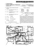
[0020] Referring to the drawings and initially to FIG. 1, there is shown an embodiment of the renewable energy hydrogen power generation system 10 according to the present invention. The system 10 has renewal energy module 12 adapted to generate electrical power from wind turbines 14, solar collectors which in this embodiment are photovoltaic cells 16 and hydro turbines 18. The wind turbines generate electric power at about 48V DC. The photovoltaic cells produce electric power at about 12V DC and the hydro turbines at about 6 to 9V DC. The module 12 uses a DC/DC converter to regulate its output at about 48V DC.
[0021] The system 10 also has a hydrogen power generation module 20 having an electrolysis separation unit 22 for separating water (H2O) into hydrogen and oxygen components, a compressor 24 for compressing the hydrogen and feeding it into a metal hydride storage 26, and a hydrogen fuel cell assembly 28 adapted to receive hydrogen from the storage 26. The fuel cell assembly 28 is formed of a stack of fuel cells which facilitate an electrochemical reaction between oxygen and hydrogen to produce electric power and water at an elevated temperature of about 80°. The oxygen is extracted from air that is introduced into the fuel cells.
[0022] The DC electric powers from the renewable energy module 12 and the hydrogen power module 20 are controllably supplied to an AC power utility module 30 which uses an inverter 32 to convert the DC power into AC power for operating electric consuming devices 34 such as lighting equipment, winches, pumps, and devices generally available at a hotel. Excess power is fed to a DC power storage module 40 for charging batteries 42 and/or super capacitors 44.
[0023] The warm water from the fuel cell assembly 28 is fed into a heating ventilation and air conditioning module (HVAC) 50 having an air conditioning system 52 for conditioning air temperature in a building. A part of the warm water may be diverted into a potable water module 60 for providing potable water. The module 60 has a distilled water tank 62 to which the warm water is delivered and a mineralization tank 64 for adding desired minerals to the water from the tank 62.
[0024] The system 10 also has a water purification module 70 for producing desalinated water from sea water. In this embodiment, the module 70 use a reverse osmosis unit 72 for separating saline from sea water. The purified water is fed into the distilled water tank 62 and the saline waste is discarded as a by-product. Low pressure pump 74 is used to draw water from sea and a high pressure pump 76 is used to supply water at a relatively high pressure at the reverse osmosis unit 72.
[0025] A low pressure pump 23 in the hydrogen power generation module 20 draws distilled water from the tank 62 and fed it into the separating unit 22 for producing hydrogen gas. A de-ionization unit may be provided for de-ionising the distilled water prior to entering the separating unit 22.
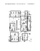
[0026] As shown in FIG. 2, the system 10 has a programmable logic controller 80 adapted to control operation of controllable components of the system.
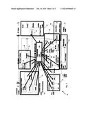
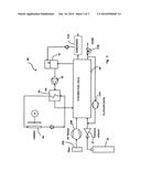
[0027] FIG. 3 shows a 60 cell stack fuel cell assembly 28 which receives hydrogen from a hydrogen storage tank 26. A pressure reducer 27 reduces the pressure of the hydrogen from the tank 26 before reaching the assembly 28. Hydrogen passing through the assembly 28 may be returned by a recycle pump 27A or purged through a valve 27B.
[0028] An air blower 29A draws air through a filter 29B into the assembly 28. Water formed during the electrochemical reaction between hydrogen and oxygen in the assembly 28 is passed through a condenser 52 A of the HVAC 52 as described above and a part of the water is fed into a humidifier 90. The water is fed to a spray tower 91 where it humidifies return air from the assembly 28. A pump 92 forces the humidified air to give up certain heat at a heat exchanger 93 before returning to the assembly 28. A flowable heat transfer medium receives heat at the exchanger 93 and releases the heat via a radiator 94.
[0029] For safe operating environment, the fuel cell assembly 28 must operate within safe operation parameters. The controller 80 or a dedicated controller (not shown) is adapted to configure and control operation of the assembly 28. Typically, the procedure for operating the assembly involves:
[0030] Start Up
[0031] 1. Start cooling circuit;
[0032] 2. Start heater in cooling circuit;
[0033] 3. Start flushing cathode with air;
[0034] 4. Start flushing anode with nitrogen;
[0035] Control
[0036] coolant flow rate <200 kg/h--increase flow rate;
[0037] coolant heating rate >20 k/min--slow heating rate;
[0038] N2 flow rate in anode <32 Nl/min--increase flow rate;
[0039] air flow rate in cathode <65 Ml/min--decrease flow rate;
[0040] stack temp >65° c.--switch off coolant heater;
[0041] stack temp <60° c.--switch on coolant heater,
[0042] When
[0043] stack temp >60° c. and)
[0044] N2 flush time >20 min and) initiate operating mode
[0045] air flush time >10 min)
[0046] Operating Mode
[0047] 1. Switch to OCV (i.e. idle operation on H2);
[0048] 2. Set load point;
[0049] 3. Start H2 and air flow;
[0050] 4. Set load to stack;
[0051] Control
[0052] in coolant temp <62.5° c.--slow cooling down;
[0053] out coolant temp >67.5° c.--increase cooling rate;
[0054] pressure difference. over mea >300 m Bar--Initiate shut-down;
[0055] H2 and air stoichometric ratios out of balance--adjust;
[0056] cell voltage >9.8V--decrease H2 and air stoic mix;
[0057] cell voltage <0.55V--increase H2 and air@stoic. mix;
[0058] cell voltage <0.3V over 5 sec--alarm;
[0059] cell voltage <specified minimum--initiate shut down;
[0060] Shut Down
[0061] 1. switch to OCV;
[0062] 2. close H2 supply valve;
[0063] 3. switch off air flow;
[0064] 4. purge anode with H2 for 10 min;
[0065] 5. shut down cooling circuit.
[0066] Whilst the above has been given by way of illustrative example of the present invention many variations and modifications thereto will be apparent to those skilled in the art without departing from the broad ambit and scope of the invention as herein set forth in the following claims.
User Contributions:
Comment about this patent or add new information about this topic:
Images included with this patent application:
 |  |
 |  |
| Similar patent applications: | |
| Date | Title |
|---|---|
| 2014-11-20 | Wireless door lock power transfer system having communications capabilities |
| 2014-11-20 | System and method for charging the energy storage cells of an energy storage device |
| 2014-03-06 | Energy conversion system |
| 2014-10-30 | Vehicle and power transfer system |
| 2014-11-13 | Electronic unit and power feeding system |
| Top Inventors for class "Electricity: battery or capacitor charging or discharging" | |
| Rank | Inventor's name |
|---|---|
| 1 | Shinji Ichikawa |
| 2 | Guoxing Li |
| 3 | Chun-Kil Jung |
| 4 | Juergen Mack |
| 5 | Nam Yun Kim |