Patent application title: Dual/Redundant Self Check Ultraviolet Flame Sensor and Combustion Safeguard Control
Inventors:
Bruce George Yates (Des Plaines, IL, US)
IPC8 Class: AF23N508FI
USPC Class:
431 79
Class name: Of shutdown by response to sensed combustion failure or overheat by electrical control circuit photoelectric sensor
Publication date: 2014-09-25
Patent application number: 20140287369
Abstract:
Two UV tubes are contained in one ultraviolet sensor to monitor one
burner flame. Each UV tube is powered during a different time cycle to
eliminate interference between the two UV tubes. This is made possible by
two rectifier circuits being powered by two transformers that are
180° out of phase with each other. Self check is accomplished by
the redundancy of two amplifiers providing output to two flame relays so
that if one UV tube was to fail in the conducting mode, the combustion
safeguard control will continue to safely monitor the flame by powering
the fuel valve when the flame is present and removing power to the fuel
valve when the flame goes out.Claims:
1. In a burner fuel valve control, a control circuit consists of two UV
tubes in one sensor housing, the rectifier circuits, two transformers
180.degree. out of phase with each other, two amplifiers, two flame
relays (output from amplifier), a safe start circuit and an output
circuit controlling said burner fuel valve in response to combined
circuit.
2. The control circuit of claim 1 wherein output circuit opens fuel valve in response to said presence of UV rays.
3. The control circuit of claim 1 wherein output circuit closes fuel valve in response to said absence of UV rays.
4. The control circuit of claim 1 wherein output circuit closes fuel valve in response to said absence of UV rays even if a UV tube fails in a conducting mode.
Description:
BACKGROUND OF THE INVENTION
[0001] Industrial burners utilize a flame sensor with a combustion safeguard control to enable opening of the fuel valve(s) in the presence of a flame or conversely, to close the fuel valve(s) in the absence of a flame. The preferred optical flame detector is an ultraviolet sensitive, cold cathode, gas discharge tube, hereinafter generally referred to as a UV tube. When ultraviolet rays from a flame are incident upon the UV tube and sufficient voltage potential exists across the electrodes in the tube, the UV tube conducts. This current is an input to a combustion safeguard control, which amplifies this input and provides an output to the fuel valve(s). It is possible for a UV tube to fail in the conduction mode with no UV present. Self check UV tube sensors with mechanical shutters that intermittently shield the UV tube from the flame to identify a failed UV tube are subject to mechanical failure due to wear and temperature degradation on the moving parts.
BRIEF DESCRIPTION OF THE SEVERAL DRAWING VIEWS
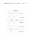
[0002] FIG. 1 is a series of diagrams illustrating voltage waveforms;
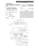
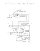
[0003] FIG. 2 is a wiring diagram illustrating the interconnection of the dual/redundant self check ultraviolet sensor, the combustion safeguard control with transformer 180° phase differential, and burner fuel valve(s).
DESCRIPTION OF THE INVENTION
[0004] The purpose of this invention is to include two UV tubes in one ultraviolet sensor to monitor one burner flame. Since UV tubes produce UV rays when they conduct, two UV tubes in one sensor would not normally be suitable for sensing a burner flame, as one UV tube could be responding to the other tube and not the flame.
[0005] The Dual/Redundant self check ultraviolet flame sensor and combustion safeguard control features voltage supply to the UV tubes that are out of phase with each other. When one UV tube is powered and may respond to UV rays, the other UV tube is off. The two UV tubes are powered thru two rectifier circuits from two transformers that are out of phase with each other. The two UV tubes are powered and sense UV from the flame on alternating half cycles (See FIG. 1.) Each UV tube and rectifier circuit provides input to its own amplifier. Each amplifier provides input to its own flame relay (See FIG. 2.) Upon burner startup, before burner ignition, if either UV tube is in conduction, the safe start check circuit does not permit powering the fuel valve.
[0006] During the burner run cycle, if either UV tube fails in a conduction state, the cycle will safely continue with the other UV tube sensing the burner flame.
User Contributions:
Comment about this patent or add new information about this topic:
| People who visited this patent also read: | |
| Patent application number | Title |
|---|---|
| 20220178155 | SCAFFOLD ROSETTE |
| 20220178154 | SCAFFOLD RACK |
| 20220178153 | Work Platform and Method |
| 20220178152 | SUPPORTING DEVICE FOR LAYING TILES |
| 20220178151 | FOAM BOARD ARTICLES |
Images included with this patent application:
 |  |
 |  |
| Similar patent applications: | |
| Date | Title |
|---|---|
| 2014-09-25 | Premixed flame location control |
| 2014-12-18 | Combustor for discrete low and high pressure vapour combustion |
| 2014-08-28 | Reduced emissions combustor |
| 2014-11-06 | Device and method for spraying a combustible liquid |
| 2014-09-11 | Dynamic flame control |
| New patent applications in this class: | |
| Date | Title |
|---|---|
| 2016-05-05 | Heating system shut-off saftey device |
| 2014-07-31 | Systems, methods, and computer program products providing flame detection |
| 2013-10-17 | Flame sensor |
| 2008-12-04 | Method for evaluating the state of a fuel/air mixture |
| Top Inventors for class "Combustion" | |
| Rank | Inventor's name |
|---|---|
| 1 | Christopher A. Wiklof |
| 2 | Igor A. Krichtafovitch |
| 3 | Joseph Colannino |
| 4 | David Deng |
| 5 | Robert E. Breidenthal |