Patent application title: Pump Control
Inventors:
Bastiaan Egbertus Streefkerk (Newtown, GB)
Michael Eling (Newtown, GB)
Assignees:
Control Techniques Limited
IPC8 Class: AF04B4920FI
USPC Class:
417 1
Class name: Pumps condition responsive control of pump drive motor
Publication date: 2014-09-25
Patent application number: 20140286792
Abstract:
A method for configuring a drive to control the operation of a pump in a
sewage system is disclosed. The method comprises measuring at least one
parameter of the sewage system; using the measurement of the at least on
parameter to create an algorithm for the drive to control the operation
of the pump; and configuring the drive to use the algorithm to control
the operation of the pump.Claims:
1. A method for configuring a drive to control the operation of a pump in
a sewage system, the method comprising: measuring at least one parameter
of the sewage system; using the measurement of the at least one parameter
to create an algorithm for the drive to control the operation of the
pump; and configuring the drive to use the algorithm to control the
operation of the pump.
2. A method as claimed in claim 1, wherein the drive is configured to use the algorithm to determine when to implement a cleaning mode of operation for the pump.
3. A method as claimed in claim 1, wherein the algorithm is configured to calculate an expected electric current for the drive for a given operating condition of the drive.
4. A method as claimed in claim 3, wherein the expected electric current is the active current drawn by the pump.
5. A method as claimed in claim 3, wherein the drive is configured to monitor an actual electric current in use corresponding to the expected electric current and optionally wherein the drive is configured to compare the actual electric current with the expected electric current for the present operating condition of the drive.
6. A method as claimed in claim 5, wherein, based on the comparison of the actual electric current with the expected electric current, the drive is configured to determine whether to alter the operation of the pump.
7. A method as claimed in claim 1, wherein the at least one parameter comprises an output frequency of an alternating current output by the drive.
8. A method as claimed in claim 1, wherein the at least one parameter comprises a wet well level of a wet well in the sewage system, the wet well being associated with the pump controlled by the drive.
9. A method as claimed in claim 1, wherein the at least one parameter comprises a number of pumps active in a sewage pumping station in the sewage system, the sewage pumping station comprising a plurality of pumps including the pump controlled by the drive.
10. A method as claimed in claim 1, wherein the at least one parameter comprises an output frequency of an alternating current output by another drive in a sewage pumping station in the sewage system, the sewage pumping station comprising a plurality of pumps including the pump controlled by the drive.
11. A method as claimed in claim 1, wherein the drive is one of a plurality of drives configured to operate in the sewage system, each of the drives being configured to drive a respective pump of a plurality of pumps in the sewage system.
12. A method as claimed in claim 1, wherein the sewage system comprises a sewage pumping station, in which the pump is situated and optionally wherein the sewage pumping station comprises a plurality of pumps, each of the plurality of pumps being operable by a respective drive, and further optionally wherein the drive is configured to communicate with at least one other drive associated with a respective other pump in the same and/or another sewage pumping station.
13. A method for creating an algorithm for a drive to operate a pump in a sewage system, the method comprising: measuring at least one parameter of the sewage system; and using the measurement of the at least one parameter to create an algorithm for the drive to control the operation of the pump.
14. A computer-readable medium comprising an algorithm created by the method of claim 13.
15. A drive configured to control the operation of a pump in a sewage system using an algorithm created by a method comprising: measuring at least one parameter of the sewage system; and using the measurement of the at least one parameter to create the algorithm.
16. A drive configured by the method of claim 1.
17. A drive configured by the method of claim 13.
18. A sewage pumping station comprising at least two pumps controlled by respective drives each according to claim 15, wherein the algorithm created for each respective drive is different and optionally wherein the algorithm created for each respective drive is based on a respective operating condition for the respective drive.
19. A sewage pumping station comprising at least two pumps controlled by respective drives each according to claim 16, wherein the algorithm created for each respective drive is different and optionally wherein the algorithm created for each respective drive is based on a respective operating condition for the respective drive.
20. A sewage pumping station comprising at least two pumps controlled by respective drives each according to claim 17, wherein the algorithm created for each respective drive is different and optionally wherein the algorithm created for each respective drive is based on a respective operating condition for the respective drive.
Description:
CROSS-REFERENCE TO RELATED APPLICATION
[0001] This application claims the benefit and priority of Great Britain Patent Application No. 1305054.7 filed Mar. 19, 2013. The entire disclosure of the above application is incorporated herein by reference.
FIELD
[0002] This disclosure relates to pump control, in particular to the control of a sewage pump by a drive.
BACKGROUND
[0003] In a sewage system, sewage from, for example, a household, is to be transported through a pipeline to a water treatment system. The transport occurs mainly due to gravity, but there is often at least one part of the sewage system that requires the sewage to be raised up. This is commonly achieved by a sewage pump at a sewage pumping station. Sewage arrives at the sewage pumping station and collects in a wet well. A sewage pump acts to pump the sewage upwards, often by the use of an impeller in the sewage pump.
[0004] The pump is powered and controlled by a drive (also known as a drive unit), which may be situated away from the pump outside the wet well, and may power the pump using a cable between the drive and the pump. Such a drive is able to control the frequency of rotation of the impeller in the pump.
[0005] Given the nature of the material being pumped, it is possible for the impeller in the pump to become clogged up and/or for material to become stuck to the impeller, thereby decreasing the effectiveness of the pump. This is known as "ragging". In order to restore the pump to its full operability, it is necessary for the pump to be cleaned (known as "de-ragging"). Manual cleaning of the pump is expensive and involves the pump having to be taken out of action while it is cleaned. A preferred de-ragging method is for the drive to carry out a cleaning mode, in which the frequency of rotation of the impeller is varied such that the material on the impeller is removed from the impeller. The routine carried out by the pump in the cleaning mode typically takes a few minutes.
[0006] It has been established by the inventors that, in current systems, the cleaning mode is sometimes initiated based on a "false alarm". For example, the drive may monitor certain conditions in order to establish whether ragging has occurred, and will initiate the cleaning mode when these conditions are found. However, different pumps in different pumping stations experience different conditions due to their situation within the sewage system, such that the monitored conditions for one pump may indicate that ragging has occurred, whereas in fact it has not. Analogously, it is also possible that a drive would not detect ragging suitably early for a pump in other operating conditions.
[0007] Such situations reduce the efficiency of the pump, either by initiating the cleaning mode unnecessarily, or by allowing ragging to occur for a prolonged period before it is fixed.
SUMMARY
[0008] An invention is set out in each of the independent claims. Optional features are set out in the dependent claims.
[0009] According to an aspect there is provided a method for configuring a drive to control the operation of a pump in a sewage system, the method comprising: measuring at least one parameter of the sewage system; using the measurement of the at least one parameter to create an algorithm for the drive to control the operation of the pump; and configuring the drive to use the algorithm to control the operation of the pump. According to an aspect there is provided a drive configured by this method.
[0010] According to an aspect there is provided a method for creating an algorithm for a drive to operate a pump in a sewage system, the method comprising: measuring at least one parameter of the sewage system; and using the measurement of the at least one parameter to create an algorithm for the drive to control the operation of the pump. According to an aspect there is provided a computer-readable medium comprising an algorithm created by this method.
[0011] According to an aspect there is provided a drive configured to control the operation of a pump in a sewage system using an algorithm created by a method comprising: measuring at least one parameter of the sewage system; and using the measurement of the at least one parameter to create the algorithm.
[0012] According to an aspect there is provided a sewage pumping station comprising at least two pumps controlled by respective drives according to one of the drives described above, wherein the algorithm created for each respective drive is different.
[0013] In some embodiments, the drive is configured to use the algorithm to determine when to implement a cleaning mode of operation for the pump.
[0014] In some embodiments, the algorithm is configured to calculate an expected electric current for the drive for a given operating condition of the drive.
[0015] In some embodiments, the expected electric current is the active current drawn by the pump.
[0016] In some embodiments, the drive is configured to monitor an actual electric current in use corresponding to the expected electric current.
[0017] In some embodiments, the drive is configured to compare the actual electric current with the expected electric current for the present operating condition of the drive.
[0018] In some embodiments, based on the comparison of the actual electric current with the expected electric current, the drive is configured to determine whether to alter the operation of the pump.
[0019] In some embodiments, the at least one parameter comprises an output frequency of an alternating current output by the drive.
[0020] In some embodiments, the at least one parameter comprises a wet well level of a wet well in the sewage system, the wet well being associated with the pump controlled by the drive.
[0021] In some embodiments, the at least one parameter comprises a number of pumps active in a sewage pumping station in the sewage system, the sewage pumping station comprising a plurality of pumps including the pump controlled by the drive.
[0022] In some embodiments, the at least one parameter comprises an output frequency of an alternating current output by another drive in a sewage pumping station in the sewage system, the sewage pumping station comprising a plurality of pumps including the pump controlled by the drive.
[0023] In some embodiments, the drive is one of a plurality of drives configured to operate in the sewage system, each of the drives being configured to drive a respective pump of a plurality of pumps in the sewage system.
[0024] In some embodiments, the sewage system comprises a sewage pumping station, in which the pump is situated.
[0025] In some embodiments, the sewage pumping station comprises a plurality of pumps, each of the plurality of pumps being operable by a respective drive.
[0026] In some embodiments, the drive is configured to communicate with at least one other drive associated with a respective other pump in the sewage pumping station.
[0027] In some embodiments, the drive is configured to communicate with at least one other drive associated with a respective pump in another sewage pumping station in the sewage system.
[0028] At least some of the aspects and embodiments described herein provide a number of advantages, some of which are now described.
[0029] As the pump operates more reliably, there is less likely to be a need for manual cleaning or maintenance of the pump. This reduces the amount of time the pump would be out of action for such maintenance. The amount of time the pump is out of action is also reduced by minimising the number of "false alarm" cleaning mode initiations. Energy is saved due to the reduced power requirements of a clean pump as opposed to a pump that has undergone ragging.
[0030] The measurements made, which are used in creating the algorithm, ensure that the drive is configured appropriately for the particular operating environment of the pump that it is to control. The drive will therefore operate more effectively than if it were merely using a general algorithm not specific to its own operating environment. This is particularly the case when the sewage system comprises a plurality of pumps, with each pump being controlled by a respective drive. Some of the plurality of pumps may be situated in the same pumping station as the pump controlled by the drive, and/or some of the plurality of pumps may be located in other pumping stations in the sewage system, which may be upstream or downstream of the pumping station containing the pump controlled by the drives.
[0031] When there is more than one pump in the same sewage system, the pressure experienced by one pump in the system will vary due to the effects of the other pumps. This therefore alters the conditions of the drive in which the cleaning mode should be initiated. Due to the measurements made, the situation of the pump within the sewage system can be accounted for.
[0032] In some embodiments, each drive in the sewage system is provided with its own algorithm that is tailored to its specific operating environment.
[0033] In some embodiments, the drive communicates with other drives in its pumping station and/or in other pumping stations to ensure that one or more of the other pumps controlled by the other drives is not already in a cleaning mode if it is determined that the drive should initiate the cleaning mode for its pump. In such a situation, the drive would wait for the other pump to finish its cleaning mode before initiating its own cleaning mode.
DRAWINGS
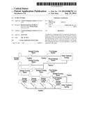
[0034] FIG. 1 depicts schematic diagrams of four sewage systems;
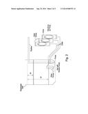
[0035] FIG. 2 depicts a schematic diagram of a sewage pumping station; and
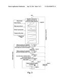
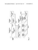
[0036] FIG. 3 depicts a flow diagram illustrating the processes involved in the present disclosure.
DETAILED DESCRIPTION
[0037] With reference to FIG. 1, first, second, third and fourth sewage systems are described. Each sewage system comprises at least one sewage source (for example, a household, building or town), which is connected to a water treatment system by at least one pipeline. At least one sewage pumping station is positioned along the pipeline between at least one of the sewage sources and the water treatment system.
[0038] The first sewage system comprises a single sewage source, a single pipeline and a single sewage pumping station along the pipeline. The second sewage system comprises two sewage sources, each having a respective pipeline and sewage pumping station in parallel, which combine to form a single pipeline before the water treatment system is reached. The third sewage system is similar to the first, but has a plurality of sewage pumping stations in series along the pipeline (in this example there are three sewage pumping stations). The fourth sewage system is similar to the second sewage system, but this system has a plurality of sewage sources each having its own pumping station, and the respective pipelines then successively combine in turn (in this example there are four sewage sources and four respective sewage pumping stations).
[0039] With reference to FIG. 2, a sewage pumping station is described in more detail. The sewage pumping station comprises a wastewater well (also known as a wet well), in which sewage is collected, having arrived from a sewage source, or an earlier sewage pumping station along the pipeline. A pump is situated inside the wastewater well, proximal to the bottom of the wastewater well, and is used to pump sewage up through the following pipeline, as described above. The pump comprises an impeller (not shown). The pump is controlled by a drive. In this sewage pumping station, a plurality of other pumps is also contained within the wastewater well, each of these other pumps being controlled by respective other drives. The drives are situated outside the wastewater well, and control the respective pumps via a respective cable. In this embodiment, the pumps in the sewage pumping station are configured to run in a constant flow regime (in normal use).
[0040] With reference to FIG. 3, the development and use of an algorithm for the drive is described. The algorithm is tailored specifically to the drive, which may correspond to any of the drives in any of the sewage pumping stations in the various sewage systems shown in FIG. 1, or other such sewage systems.
[0041] In developing the algorithm for the particular drive, first, a measurement phase is carried out, in which one or more parameters of the sewage system are measured. In this embodiment, the parameters measured are an output frequency, an active current, a wastewater well level, a frequency of other pumps and a number of pumps active. The output frequency is the frequency of the AC current output of the drive, which corresponds to the frequency of rotation of the impeller of the pump, enabling the speed (flow rate) of the pump to be measured. This parameter is derivable from the drive. The active current is the active current drawn by the pump. This parameter is derivable from the drive. The wastewater well level is the height of the fluid contained within the wastewater well measured from the bottom of the wastewater well, which varies over time and depends upon the rate of flow into the wastewater well and the rate of flow out of the wastewater well through the pumps. This is measured directly from the wastewater well, using a measuring device. The frequency of other pumps provides the same information as the output frequency, but for the other pumps in the sewage pumping station. This parameter is obtained from a communication path between the particular drive and the other drives. The number of pumps active is the number of the other pumps in use in the sewage station, which enables the drive to be configured with an awareness of the effects of the other drives in the sewage pumping station. This parameter is derivable from the frequency of other pumps, with those having zero frequency being inactive.
[0042] The measurement phase may last for up to several weeks, in order to obtain a detailed set of data for the whole system taking into account all of the variables.
[0043] The raw data from the measurement phase is recorded and analysed. The data is plotted into a graph for each day, which enables a trained engineer to recognise patterns, and in particular recognise at which point the pump has been manually cleaned by the end-user (this results in a sudden change in the measured active current after a start of the pump). The data identified as corresponding to a time immediately after a manual cleaning of the pump is used to determine the characteristics of the pump (known as the pump curve).
[0044] The measurements from the measurement phase are used to create an algorithm. The algorithm is configured to calculate an expected electric current for the drive. The expected electrical current is the active current drawn by the pump. The active current provides an accurate representation of the power used by the pump (and hence the torque produced by the pump).
[0045] The expected electrical current is calculated by taking into account parameters measured in real time and inputting these into the algorithm, which has been prepared in advance based on the measurements from the measurement phase. The measured parameters used by the algorithm are the pump curve (also known as the pump characteristics), the system curve (also known as the system characteristics), the influence of the other pumps in the system and the wastewater well level. The influence of the other pumps in the system is relevant because the pressure in the sewage system varies due to other pumps in the sewage system. These pressure effects will therefore affect the measurement of torque of the impeller derived from the current measurement. The wastewater well level is measured by a measuring device and enables the amount of sewage in the wastewater well to be determined.
[0046] Data identified as corresponding to a time immediately after a manual cleaning of the pump is used as the start position for the algorithm. The data is filtered and categorised to represent an active current in the different situations that occurred during the measurement phase. The different situations are the variable frequency, the wastewater well level and the frequency of the pumps at the sewage pumping station, and potentially also including pumps in another station on the same pipeline.
[0047] Extreme high and low values are filtered to achieve a representative characteristic for each possible situation. The representative characteristics are again analysed, and are displayed in graphs. The graphs are analysed and a function or combination of functions is set up to model the graphs for each analysed situation of the system. The mathematical functions created comprise a combination of linear and square functions with an offset on the starting point of the function. In some less-complicated systems, a step-response with a few set points will suffice.
[0048] The created functions are used to produce the algorithm, which takes the variables into account. The created algorithm is implemented in software running on an application module fitted in the drive. To test the algorithm and ensure its accuracy, the expected electrical current calculated by the algorithm is recorded together with other data measured in use. This data is then analysed and used to create a new graph. When the algorithm is working correctly, the difference between the expected electrical current and the measured active current for a clean pump will be close to zero (typical values are less than one percent of the nominal full load current).
[0049] After testing the algorithm to ensure its accuracy, the pump is monitored for a few days to see if the software is able to detect dirt at an early stage and successfully de-rag the pump. Some fine-tuning may be applied to optimise the performance of the system by keeping the amount of cleaning cycles as low as possible without getting an excessive build-up of dirt to a point where manual cleaning is needed.
[0050] The output of the algorithm is the expected electrical current. This is then used in a determination phase, in which it is determined whether the drive is to implement a cleaning mode for the pump, as is now described.
[0051] When the drive is in use, the expected electric current output from the algorithm is compared with the actual electric current derived from the drive. The actual electric current is a measurement of the same type of current as that output by the algorithm, i.e. in this embodiment the active current. At block A, the difference between the expected electric current and the actual electric current is calculated. If this difference does not exceed a threshold value, the process returns to the start. If this difference does exceed a threshold value, a time delay is implemented, as shown at block B. After this delay, which is used to reduce the likelihood of a "false alarm", the difference is calculated again at block C in the same manner as block A. If the threshold is not exceeded, the process returns to the start. If the threshold is still exceeded, block D is reached, at which it is determined whether any of the other pumps are currently in a cleaning mode. The drive is able to communicate with the other drives to determine this. It is not generally appropriate for more than one pump to be undergoing a cleaning mode at the same time, as this reduces the effectiveness of the sewage pumping station as a whole, and the cleaning mode of one pump may interrupt or adversely affect the cleaning mode of another pump. Therefore, if another pump is in cleaning mode, the process returns to the start. If no other pump in the sewage pumping station is in cleaning mode, block E is reached at which it is determined whether the pump has already implemented its cleaning mode a maximum number of times (n) within a predetermined period of time (x). This maximum is provided to ensure that the cleaning mode is not carried out too often, as this would adversely affect the ability of the pumping station to carry out its main function of pumping the sewage. If the maximum has been reached, the process returns to the start. If the maximum has not yet been reached, block F is reached, at which the cleaning mode is initiated, and a cleaning cycle is carried out. The cleaning cycle involves the frequency of the impeller of the pump being altered to de-rag the pump, as described above.
[0052] After the cleaning mode has finished, the value of n is increased by one, as shown at block G, and, after a predetermined time delay at block H, the function returns to the start. The delay at block H ensures that two cleaning modes are not carried out too close together, to ensure that the pump can be used in the meantime for its main pumping duty.
[0053] The cleaning cycle, as shown at block F, involves a predetermined routine in which the frequency of the pump is varied in a predetermined manner, which may include periods of time in which the pump operates in reverse. The predetermined routine for the cleaning mode is also determined based on the measurements in the measurement phase. The cleaning cycle comprises a plurality of phases, which depend on the pump, the topology of the pipeline and the type of pollution that is mainly in the particular wastewater well. The phases are defined by different frequencies, which may be positive or negative (i.e. with the pump running in its normal direction or in revers), together with a particular acceleration time or a deceleration time.
[0054] It will be understood that the above description of specific embodiments is by way of example only and it is not intended to limit the scope of the present disclosure. Many modifications of the described embodiments, some of which are now described, are envisaged and intended to be within the scope of the present disclosure.
[0055] In some embodiments, the measurement phase involves the use of different parameters. These may be more or fewer than the parameters described above, and may include some, all or none the parameters described above. Other parameters may be used as well or instead. Examples of other parameters include the pump characteristic (i.e. the pump curve), including the configuration of the pipeline, the number of pumps, the number of other users on the pipeline, the architecture of the pipeline, pressure in the pump, the frequency of other pumps outside the sewage pumping station, but elsewhere in the sewage system.
[0056] In some embodiments, a computer carries out the tasks done by the engineer in the embodiment described above, e.g. the data corresponding to a time immediately after a manual cleaning of the pump is identified by the computer in detecting an indicative change in the measured active current after a start of the pump.
[0057] In some embodiments, the measured parameters used by the algorithm are different from those described above. These may be more or fewer than the parameters described above, and may include some, all or none the parameters described above. Other parameters may be used as well or instead.
[0058] In some embodiments, the determination phase is carried out differently, for example with some or all of the blocks described above omitted. The skilled person will appreciate that various implementations may be carried out in the determination phase without departing from the scope of the present disclosure.
[0059] In some embodiments, the expected electric current calculated by the algorithm is not the active current, as described above, but is instead the total current output from the drive.
[0060] In some embodiments, the cleaning cycle is not created specifically for the drive, but a standard cleaning cycle is used by the drive.
[0061] In some embodiments, some or all of the functionality described above while the drive is in use is implemented on a device separate from the drive. The drive may be, for example, simply informed when to implement its cleaning mode after the other steps have been carried out on the other device.
[0062] In some embodiments, the drive is in communication with one or more drives in at least one other sewage pumping station within the sewage system. This enables the drive to be aware of the situation at the at least one other sewage pumping station, which may be upstream or downstream from the sewage pumping station to which the drive is associated.
[0063] In some embodiments, the pumps in the sewage pumping station are configured to operate in a variable flow rate system (in normal use), rather than a constant flow rate system, as described above. In some embodiments, the pumps in the sewage pumping station are configured to operate in either system.
[0064] In some embodiments, the pump(s) in the sewage pumping station are situated outside the wastewater well.
User Contributions:
Comment about this patent or add new information about this topic:
Images included with this patent application:
 |  |
 |  |
| New patent applications in this class: | |
| Date | Title |
|---|---|
| 2017-08-17 | System and method for preventing floating rod effect in a sucker rod pump |
| 2014-05-01 | Switched reluctance motor assembly and method of assembling the same |
| 2014-01-23 | Tire valve - micro air pump |
| 2014-01-16 | Disengageable coolant pump for engine |
| 2013-12-26 | Pump motor control assembly |
| Top Inventors for class "Pumps" | |
| Rank | Inventor's name |
|---|---|
| 1 | Masaki Ota |
| 2 | Ken Suitou |
| 3 | Alex Horng |
| 4 | Yusuke Yamazaki |
| 5 | Lars Hoffmann Berthelsen |