Patent application title: APPARATUS AND METHOD FOR ABSORBING LASER ENERGY THAT FAILS TO COUPLE INTO THE CORE OF A LASER FIBER, AND FOR ABSORBING THE ENERGY THAT HAS BEEN TRANSMITTED TO THE CLADDING OF THE LASER
Inventors:
Joe Denton Brown (Panama City, FL, US)
Joe Denton Brown (Panama City, FL, US)
IPC8 Class: AG02B642FI
USPC Class:
385 93
Class name: Optical fiber to a nonfiber optical device connector with housing including lens
Publication date: 2014-09-18
Patent application number: 20140270661
Abstract:
A fiber optic connector for coupling focused radiant energy from a laser
to a fiber optic conductor includes a quartz alignment ferrule that is
fused mechanically and optically to the fiber's proximal end, either by
an index matching first adhesive or by heat fusing the cladding to the
ferrule without removing the cladding from the end of the fiber. The
fiber and ferrule are attached to the fiber's proximal termination
connector by a second adhesive with a high refractive index which absorbs
errant radiant energy that has propagated in the fiber's cladding. The
absorbed errant energy is dissipated by the connector assembly as it is
converted to heat.Claims:
1. A fiber optic connector arrangement for coupling focused radiant
energy from a laser to a fiber optic conductor, the fiber optic conductor
including a core and cladding, comprising: an alignment ferrule; and an
index matching first adhesive for mechanically and optically fusing the
alignment ferrule to a proximal end of the fiber optic conductor, wherein
the fiber optic conductor and ferrule are attached to a connector by a
second adhesive with a high refractive index so as to absorb errant
radiant energy that has propagated in the fiber optic conductor's
cladding.
2. A fiber optic connector arrangement as claimed in claim 1, wherein the ferrule is a quartz alignment ferrule.
3. A fiber optic connector arrangement as claimed in claim 1, wherein the connector is a proximal termination connector with a coupling nut.
4. A fiber optic connector arrangement for coupling focused radiant energy from a laser to a fiber optic conductor, the fiber optic conductor including a core and cladding, comprising: an alignment ferrule, wherein the cladding of the fiber optic conductor is heat fused to the ferrule without removing the cladding from the end of the fiber optic conductor; and an adhesive for attaching the fiber optic conductor and ferrule to a connector, wherein the adhesive has a high refractive index so as to absorb errant radiant energy that has propagated in the fiber optic conductor's cladding.
5. A fiber optic connector arrangement as claimed in claim 4, wherein the ferrule is a quartz alignment ferrule.
6. A fiber optic connector arrangement as claimed in claim 4, wherein the connector is a proximal termination connector with a coupling nut.
Description:
[0001] This application claims the benefit of U.S. provisional patent
application Ser. No. 61/788,238, filed Mar. 15, 2013, and incorporated
herein by reference.
BACKGROUND OF THE INVENTION
[0002] 1. Field of the Invention
[0003] This invention relates to a fiber optic connector and connector system or arrangement for coupling focused radiant energy from a laser to a fiber optic conductor.
[0004] 2. Description of Related Art
[0005] The invention provides an improvement to the connector arrangements disclosed in the Inventor's U.S. Pat. Nos. 5,179,610 and 7,090,411, incorporated by reference herein. In the connectors disclosed in the cited patents, radiation that fails to couple with a small core fiber and radiation which couples with higher order propagation modes is absorbed by the connector or surrounding structures. The improvement permits the use of a fiber with full cladding, thereby making the fiber termination more rugged and simplifying manufacturability.
SUMMARY OF THE INVENTION
[0006] A fiber optic connector for coupling focused radiant energy from a laser to a fiber optic conductor includes a quartz alignment ferrule that is fused mechanically and optically to the fiber's proximal end, either by an index matching first adhesive or by heat fusing the cladding to the ferrule without removing the cladding from the end of the fiber. The fiber and ferrule are attached to the fiber's proximal termination connector by an adhesive with a high refractive index which absorbs errant radiant energy that has propagated in the fiber's cladding. The absorbed errant energy is dissipated by the connector assembly as it is converted to heat.
BRIEF DESCRIPTION OF THE DRAWINGS
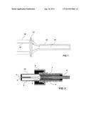
[0007] FIG. 1 is a schematic depiction showing the effects of thermal lensing on coupling of a focused laser beam to the core and cladding of the fiber.
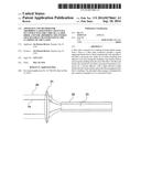
[0008] FIG. 2 is a cross-sectional side view of proximal terminal connector constructed in accordance with the principles of a preferred embodiment of the invention.
DETAILED DESCRIPTION OF THE PREFERRED EMBODIMENTS
[0009] As shown in FIG. 1, a laser beam 19 is focused into the fiber core 23 by the laser's focusing lens 21 with a half angle of acceptance (θ1). However, due to thermal lensing, an expanded beam 20 is focused into both the fiber core 23 and cladding 22 with a half angle of acceptance (θ2). The present invention uses refractive index matching adhesives to provide a path for dissipation of the energy in the cladding to a heat sink in the form of a ferrule and/or structures in contact with the ferrule.
[0010] As shown in FIG. 2, the termination arrangement of a preferred embodiment of the invention is included in a proximal termination connector 10 and threaded nut 8, although the illustrated connector and nut configuration should not be taken as limiting since the invention can be applied to a variety of termination connectors, including ones without nuts.
[0011] The fiber inside the connector consists of a fiber core 1, cladding 2, coating 7, and buffer 6. The fiber is fused to the quartz ferrule 3 by a refractive index matching first adhesive 4 or by heat fusing the cladding 2 to the ferrule 3 without removing the cladding from the end of the fiber, and the fiber and ferrule are secured in the connector by a high refractive index second adhesive 5, thereby providing a dissipation path for energy that has coupled to the cladding 2 rather than to the core 1 of the fiber.
[0012] Having thus described a preferred embodiment of the invention in connection with the accompanying drawings, it will be appreciated that the invention is not to be limited to the specific embodiments or variations disclosed.
User Contributions:
Comment about this patent or add new information about this topic:
| People who visited this patent also read: | |
| Patent application number | Title |
|---|---|
| 20150115278 | LIGHT EMITTING DEVICE, AND METHOD FOR MANUFACTURING THEREOF |
| 20150115277 | Episubstrates for Selective Area Growth of Group III-V Material and a Method for Fabricating a Group III-V Material on a Silicon Substrate |
| 20150115276 | LIGHT-EMITTING DIODE |
| 20150115275 | DISPLAY DEVICE |
| 20150115274 | DISPLAY DEVICE |
Images included with this patent application:
 |  |
| New patent applications in this class: | |
| Date | Title |
|---|---|
| 2016-06-16 | Optical fiber securing device |
| 2016-06-09 | Electro-optical connector systems incorporating gradient-index lenses |
| 2016-05-05 | Pigtailed laser device based on spherical lens coupling |
| 2015-11-12 | Alignment jig for optical lens array |
| 2015-10-29 | Optical connectors for coupling light sources to optical fibers |
| New patent applications from these inventors: | |
| Date | Title |
|---|---|
| 2014-10-23 | Protective sheath for surgical laser fiber |
| 2013-12-26 | End fire fiber arrangements with improved erosion resistance |
| 2013-08-22 | Protective sheath and method of using same for laser surgery |
| 2011-12-01 | Method and apparatus for using optical feedback to detect fiber breakdown during surgical laser procedures |
| 2011-09-01 | Apparatus and method for detecting overheating during laser surgery |
| Top Inventors for class "Optical waveguides" | |
| Rank | Inventor's name |
|---|---|
| 1 | James Phillip Luther |
| 2 | Trevor D. Smith |
| 3 | Ming-Jun Li |
| 4 | Micah Colen Isenhour |
| 5 | Dennis Michael Knecht |