Patent application title: STEERABLE TRAILER CHASSIS
Inventors:
Kevin Stuart Carr (Richmond, VA, US)
IPC8 Class: AB62D1302FI
USPC Class:
280426
Class name: Articulated vehicle semitrailer steering by articulative movement
Publication date: 2014-09-18
Patent application number: 20140265243
Abstract:
A steerable trailer provides the ability to offset the center line of the
trailer to the tow vehicle with a swivel tung and pivoting axels. The
steerable trailer can alter the turning radius of the trailer and improve
the turning and backing of the trailer. Typically, a trailer moves
relative to the tow vehicle. The steerable trailer allows a user to
control the trailer steering independently from the tow vehicle and adds
up to two more points to steer more accurately and safely in close areas,
for example. The swiveling tung and pivoting axels can be used
independently or together to position the trailer safely in different
radii.Claims:
1. A steerable trailer comprising: a main frame assembly; a main frame
receiver bracket attached to the main frame assembly; at least one
connector receiver disposed on at least one end of the main frame
receiver bracket; at least one wheel frame assembly pivotably attached to
the at least one connector receiver with a wheel frame assembly
connector; a main frame connector disposed on the main frame, forward of
the wheel frame assembly; and a pivot frame assembly pivotably connected
to the main frame connector and extending beyond a front end of the main
frame assembly.
2. The steerable trailer of claim 1, further comprising a plurality of roller bearings disposed on a bottom side of at least a portion of the main frame assembly where the pivot frame assembly pivots thereupon.
3. The steerable trailer of claim 1, wherein the at least one wheel frame assembly includes a forward wheel frame assembly and a rear wheel frame assembly.
4. The steerable trailer of claim 3, wherein the forward wheel frame assembly and the rear wheel frame assembly are interconnected with two or more connectors.
5. The steerable trailer of claim 3, wherein the at least one connector receiver includes first and second connector receivers disposed on opposite ends of the main frame receiver bracket.
6. The steerable trailer of claim 1, further comprising an actuator operable to pivot at least one of the wheel frame assemblies relative to the main frame assembly.
7. The steerable trailer of claim 1, further comprising an actuator operable to pivot the pivot frame assembly relative to the main frame assembly.
8. A steerable trailer comprising: a main frame assembly; a main frame receiver bracket attached to the main frame assembly; first and second connector receivers disposed on opposite ends of the main frame receiver bracket; first and second wheel frame assemblies pivotably attached to the first and second connector receivers with a wheel frame assembly connector; at least two connectors interconnecting the first and second wheel frame assemblies; a main frame connector disposed on the main frame, forward of the wheel frame assemblies; and a pivot frame assembly pivotably connected to the main frame connector and extending beyond a front end of the main frame assembly.
9. The steerable trailer of claim 8, further comprising an actuator operable to pivot the first and second wheel frame assemblies relative to the main frame assembly.
10. The steerable trailer of claim 8, further comprising an actuator operable to pivot the pivot frame assembly relative to the main frame assembly.
Description:
BACKGROUND OF THE INVENTION
[0001] The present invention relates to a steerable trailer chassis and, more particularly, to a steerable trailer that can offset the center line of the trailer to the tow vehicle, using a swivel tung and pivoting axels to alter the turning radius of the trailer to improve the turning and backing.
[0002] Conventional trailers do not track in the same radius as the tow vehicle. A regular trailer moves in relationship to the steering of the tow vehicle. This can make the control of the trailer difficult, especially when attempting to position the trailer in a precise location.
[0003] As can be seen, there is a need for a trailer that can be steerable to track in the same radius as the tow vehicle.
SUMMARY OF THE INVENTION
[0004] In one aspect of the present invention, a steerable trailer comprises a main frame assembly; a main frame receiver bracket attached to the main frame assembly; at least one connector receiver disposed on at least one end of the main frame receiver bracket; at least one wheel frame assembly pivotably attached to the at least one connector receiver with a wheel frame assembly connector; a main frame connector disposed on the main frame, forward of the wheel frame assembly; and a pivot frame assembly pivotably connected to the main frame connector and extending beyond a front end of the main frame assembly.
[0005] In another aspect of the present invention, a steerable trailer comprises a main frame assembly; a main frame receiver bracket attached to the main frame assembly; first and second connector receivers disposed on opposite ends of the main frame receiver bracket; first and second wheel frame assemblies pivotably attached to the first and second connector receivers with a wheel frame assembly connector; at least two connectors interconnection the first and second wheel frame assemblies; a main frame connector disposed on the main frame, forward of the wheel frame assemblies; and a pivot frame assembly pivotably connected to the main frame connector and extending beyond a front end of the main frame assembly.
[0006] These and other features, aspects and advantages of the present invention will become better understood with reference to the following drawings, description and claims.
BRIEF DESCRIPTION OF THE DRAWINGS
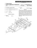
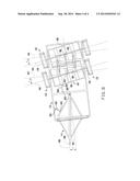
[0007] FIG. 1 is a perspective view of a steerable trailer according to an exemplary embodiment of the present invention;
[0008] FIG. 2 is a side view of the steerable trailer of FIG. 1;
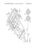
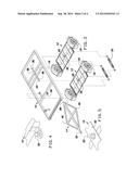
[0009] FIG. 3 is an exploded perspective view of the steerable trailer of FIG. 1;
[0010] FIG. 4 is a detailed perspective view of a tow ball and a wheel frame assembly center bar of the steerable trailer of FIG. 1;
[0011] FIG. 5 is a detailed perspective view of a main frame tow ball of the steerable trailer of FIG. 1;
[0012] FIG. 6 is a cross-sectional view taken along line 6-6 of FIG. 1;
[0013] FIG. 7 is a top view of the steerable trailer of FIG. 1; and
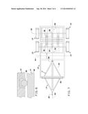
[0014] FIG. 8 is a top view of the steerable trailer of FIG. 1, illustrating a non-linear axial configuration.
DETAILED DESCRIPTION OF THE INVENTION
[0015] The following detailed description is of the best currently contemplated modes of carrying out exemplary embodiments of the invention. The description is not to be taken in a limiting sense, but is made merely for the purpose of illustrating the general principles of the invention, since the scope of the invention is best defined by the appended claims.
[0016] Broadly, an embodiment of the present invention relates to a steerable trailer that provides the ability to offset the center line of the trailer to the tow vehicle with a swivel tung and pivoting axels. The steerable trailer can alter the turning radius of the trailer and improve the turning and backing of the trailer. Typically, a trailer moves relative to the tow vehicle. The steerable trailer allows a user to control the trailer steering independently from the tow vehicle and adds up to two more points to steer more accurately and safely in close areas, for example. The swiveling tung and pivoting axels can be used independently or together to position the trailer safely in different radii.
[0017] Referring now to FIGS. 1 through 8, a main frame assembly 10 can support one or more wheel frame assemblies 12. For example, as shown in the Figures, two wheel frame assemblies 12 can each have a wheel frame center bar 32 with a wheel frame connector 20, such as a tow ball. The wheel frame connector 20 can fit into a connector receiver 24, such as a tow ball receiver, disposed on opposite ends of a main frame connector receiver bracket 36. The connection of the wheel frame connector 20 into the connector receiver 24 allows the wheel frame assemblies 12 to pivot relative to the main frame assembly 10.
[0018] The wheel frame assemblies 12 can be supported by wheels 16, typically covered with fenders 18. The wheel frame assemblies 12 can be interconnected with a plurality of connectors 33. The connectors 33 can be three such connectors interconnecting a forward one of the wheel frame assemblies 12 with a rearward one of the wheel frame assemblies 12 so that movement of one of the wheel frame assemblies 12 moves the other one of the wheel frame assemblies 12.
[0019] A main frame connector 22, such as a tow ball, can be attached to the main frame, forward of the wheel frame assemblies 12. A pivot frame assembly 14 can have a pivot frame receiver 28, such as a tow ball receiver, disposed on one end thereof and operable to receive the main frame connector 22 therein. When the main frame connector 22 is disposed in the pivot frame receiver 28, the pivot frame receiver 28 can pivot relative to the main frame assembly 10.
[0020] A tow ball receiver 30 can be disposed on an opposite end of the pivot frame assembly 14. The tow ball receiver 30 can attach to a tow ball of a vehicle (not shown). In some embodiments, the pivot frame assembly 14 can be diamond shaped with a pivot frame side bar 46 forming a cross member through the diamond shape. As shown in FIG. 6, a plurality of roller bearings 38 can be disposed on an underside of the main frame assembly 10 to permit the pivot frame assembly to smoothly move along the main frame assembly 10.
[0021] One or more actuators 60 can be attached to the main frame assembly 10 having a shaft 62 that can be extended or retracted by the actuators 60. A mount 64 can interconnect the shaft 62 with a portion of one of the wheel frame assemblies 12. When the actuator 60 is activated, the shaft 62 can extend or retract to steer the wheel frame assemblies 12. For example, as shown in FIG. 8, the shaft 62 can be retracted by the actuator 60 to move the wheel frame assemblies 12 to steer the trailer. Similarly, another mount 62 can connect the pivot frame assembly 14 with another shaft 62 attached to another actuator 60. This actuator can move the picot frame assembly 14 in a desired orientation.
[0022] As shown in FIG. 8, the pivot frame assembly 14 can be moved independently (independently of the wheel frame assemblies 12) to an angle A, an angle of pivot between a main frame long axis 40 and a pivot frame assembly long axis 48. The wheel frame assemblies 12 can be moved independently (independent of the pivot frame assembly 14) to an angle B, an angle of pivot between an axis 44 perpendicular to the main frame long axis 40 and a wheel axial axis 42.
[0023] The actuators 60 can be controlled independently to position the wheel frame assembly 12 and the pivot frame assembly 14 at desired angles. In some embodiments, adjustment of the actuators 60 can be done from within the tow vehicle. In some embodiments, the actuators 60 can be wired to the inside of the tow vehicle or can be accessed wirelessly, for example. The actuators 60 can be powered from the tow vehicle or can be powered by a battery (not shown) carried by the trailer. This battery can be, for example, solar charged to maintain its power level.
[0024] In some embodiments, the actuators 60 can be automatically adjusted. For example, GPS can be used to position the trailer and provide optimal trailer tracking.
[0025] It should be understood, of course, that the foregoing relates to exemplary embodiments of the invention and that modifications may be made without departing from the spirit and scope of the invention as set forth in the following claims.
User Contributions:
Comment about this patent or add new information about this topic:
Images included with this patent application:
 |  |
 |  |
 |
| Similar patent applications: | |
| Date | Title |
|---|---|
| 2011-05-19 | Trailer chassis |
| 2012-12-20 | Trailer chassis |
| 2013-10-17 | Steerable foam slider |
| 2014-09-18 | Adjustable roller skate |
| 2014-09-18 | Expandable trailer |
| New patent applications in this class: | |
| Date | Title |
|---|---|
| 2015-10-15 | Self-steering bogie for a road vehicle |
| 2014-09-25 | Steering system for trailers |
| 2014-05-15 | Driving support device and driving support system |
| 2014-04-03 | Lowboy trailer with steerable rear assembly |
| 2013-07-11 | Steering mechanism for a drawn vehicle to steer one or more turnable steered axles |
| Top Inventors for class "Land vehicles" | |
| Rank | Inventor's name |
|---|---|
| 1 | Osamu Fukawatase |
| 2 | Christopher P. D'Aluisio |
| 3 | Richard W. Mccoy |
| 4 | Jun Yeol Choi |
| 5 | Yusuke Fujiwara |