Patent application title: SYSTEM AND METHOD FOR BILLING A UTILITY CONSUMER AFTER INSTALLATION OF A NEW LIGHTING TECHNOLOGY
Inventors:
Neal R. Verfuerth (Manitowoc, WI, US)
Neal R. Verfuerth (Manitowoc, WI, US)
Michael J. Potts (Plymouth, WI, US)
Michael J. Potts (Plymouth, WI, US)
Assignees:
Orion Energy Systems, Inc.
IPC8 Class: AG06Q2014FI
USPC Class:
705 37
Class name: Automated electrical financial or business practice or management arrangement finance (e.g., banking, investment or credit) trading, matching, or bidding
Publication date: 2014-07-10
Patent application number: 20140195405
Abstract:
A method includes obtaining, at a metering device, power usage
information associated with operation of a second technology;
calculating, at a processor and based on the power usage information
obtained from the metering device, a power base load capacity relief of
an electrical system to a utility provider resulting from change from a
first technology to the second technology; receiving, at the processor, a
technology cost including fixed and variable costs to install and
maintain the second technology; calculating, at the processor, a return
needed for repayment of the technology cost; determining, by the
processor, a new utility rate by apportioning the return needed for
repayment of the technology cost as a function of the power base load
capacity relief and calculating; and providing a utility invoice to the
utility consumer for a power reduction over time at the new utility rate.Claims:
1. A computerized method for billing a utility consumer after
installation of a new lighting technology by the utility consumer at a
facility associated with the utility consumer, the computerized method
comprising: obtaining, at a processor, power usage information associated
with operation of a second lighting technology; calculating, at the
processor, a power base load capacity relief resulting from change from a
first lighting technology to the second lighting technology; receiving,
at the processor, a technology cost including fixed and variable costs to
install and maintain the second lighting technology; determining, by the
processor, a new utility rate by apportioning a return needed for
repayment of the technology cost as a function of the power base load
capacity relief; and calculating and providing a utility invoice to the
utility consumer for a power reduction over time at the new utility rate,
the power reduction over time provided by use of the second lighting
technology; wherein the amount billed to the utility consumer via the
utility invoice is less than a cost savings attained by the utility
consumer via the power base load capacity relief such that the amount
billed to the utility consumer is financed via a portion of the cost
savings.
2. The method of claim 1, wherein the new utility rate is not applied to actual energy use over time and the utility invoice does not request payment for energy use over time.
3. The method of claim 1, wherein calculating and providing the utility invoice are completed by the processor and a communications interface coupled to the processor.
4. The method of claim 1, wherein at least one of the new utility rate and the invoice accounts for the value of pollution credits gained through use of the second technology.
5. The method of claim 4, further comprising communicating pollution credit information to a trading exchange for trading of pollution credits.
6. The method of claim 1, wherein payment of costs is the only repayment source for installation and maintenance of the second technology.
Description:
CROSS-REFERENCE TO RELATED APPLICATIONS
[0001] This is a continuation of application Ser. No. 11/744,083, filed May 3, 2007, which is incorporated herein by reference in its entirety.
BACKGROUND
[0002] This section is intended to provide a background or context to the invention recited in the claims. The description herein may include concepts that could be pursued, but are not necessarily ones that have been previously conceived or pursued. Therefore, unless otherwise indicated herein, what is described in this section is not prior art to the description and claims in this application and is not admitted to be prior art by inclusion in this section.
[0003] Several references describe methods and systems for managing electrical power consumption. For example, U.S. Pat. No. 5,644,173 discloses a method for real time load shedding based on a tiered pricing agreement between the utility and an energy consumer. The load shedding is implemented by first receiving a signal from the utility company that load shedding is necessary to maintain the tiered pricing. The signal is then communicated to processors that determine which loads should be shed, and the appropriate loads are shed at the energy consumer's location.
[0004] U.S. Pat. No. 6,535,859 discloses a system and a method for charging a fee to an end user, where a service company services a lighting system of the end user's facility. To determine the fee, an original power consumption of the facility is determined before the lighting system is retrofitted with at least one power savings device. The lighting system is retrofitted with the at least one power saving device and a new power consumption of the facility is measured. The fee is charged to the end user, and the fee is a function of a difference between the original power consumption and the new power consumption.
[0005] U.S. Pat. No. 6,633,823 discloses a system and a method for monitoring and controlling energy usage at various facilities to allow aggregate control over power consumption. A central location communicates with facilities and monitors power usage in each facility. When the central location senses a problem or excessive energy usage, it remotely controls power consuming devices at the facility to avoid expensive spikes in power consumption.
[0006] U.S. Pat. No. 6,785,592 discloses a business method for optimizing energy usage at facilities. The energy consumption of each facility is monitored to detect economic inefficiencies. Based on contractual agreements with energy providers, devices in the facilities are remotely controlled to avoid any economic inefficiency.
[0007] U.S. Pat. No. 7,130,832 discloses a system and a method where an energy service enterprise measures energy consumption achieved due to energy-saving measures, calculates an amount of curtailed energy cost by comparing the measured value with the energy consumption before taking the energy-saving measures previously stored in the database, and receives at least a part of the curtailed amount. The customer is not required to plan equipment investment in energy-saving measures and collection thereof
[0008] U.S. Published Patent Application No. 2003/0046252 discloses a business management system for taking advantage of energy providers' special offers. Load profiles for energy consumers are created such that the appropriate special is offered by a direct energy provider. An indirect energy provider then negotiates the offer with the direct energy provider, and the indirect energy provider supplies power to the end users.
[0009] U.S. Published Patent Application No. 2004/0095237 (the "'237 application") discloses a method and a system for remote monitoring and controlling of equipment within a facility to control energy consumption. The remote monitoring and control is implemented by the utility, a government, or any other third party.
[0010] Other references for electric power utility management by an end user include U.S. Pat. Nos. 4,489,386; 5,426,620; 5,572,438; 6,122,603; 6,528,957; and 6,622,097 and U.S. Published Patent Appl. Nos. 2003/0084358; 2003/0084359; 2003/0171851; 2004/0006439; 2004/0024483; 2004/0078154; 2004/0128266; 2005/0035717; and 2005/0038571. References for electric power utility management by an energy supplier include U.S. Pat. Nos. 4,023,043; 4,135,181; 4,190,800; 4,204,194; 4,204,195; 4,360,881; 5,956,462; 6,828,695; and 6,832,135 and U.S. Published Patent Appl. Nos. 2002/0082748; 2002/0103655; and 2002/0162032. References for electric power utility management methods include U.S. Pat. Nos. 5,758,331 and 6,169,979 and U.S. Published Patent Appl. Nos. 2001/0055965; 2003/0011486; 2003/0036820; 2003/0041017; 2003/0041038; 2003/0093332; 2004/0078153; 2004/0193329; 2005/0027636; and 2005/0034023.
SUMMARY
[0011] According to an exemplary embodiment, a method for financing installation of a new utility technology by a utility consumer after installation of the new utility technology at a facility associated with the utility consumer includes obtaining, at a metering device, power usage information associated with operation of a second technology and calculating, at a processor and based on the power usage information obtained from the metering device, a power base load capacity relief of an electrical system to a utility provider resulting from change from a first technology to the second technology. The method also includes receiving, at the processor, a technology cost including fixed and variable costs to install and maintain the second technology and calculating, at the processor, a return needed for repayment of the technology cost. The method further includes determining, by the processor, a new utility rate by apportioning the return needed for repayment of the technology cost as a function of the power base load capacity relief and calculating and providing a utility invoice to the utility consumer for a power reduction over time at the new utility rate, the power reduction over time provided by use of the second technology. The amount billed to the utility consumer via the utility invoice is less than a cost savings attained by the utility consumer via the power base load capacity relief such that the amount billed to the utility consumer is financed via a portion of the cost savings.
[0012] These and other features, aspects and advantages of the present invention will become apparent from the following description, appended claims, and the accompanying exemplary embodiments shown in the drawings, which are briefly described below.
BRIEF DESCRIPTION OF FIGURES
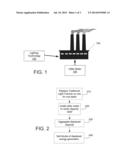
[0013] FIG. 1 is a diagram illustrating an application of a utility financial model in accordance with an exemplary embodiment.
[0014] FIG. 2 is a flow diagram depicting operations performed in a utility financial model in accordance with an exemplary embodiment.
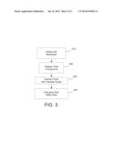
[0015] FIG. 3 is a flow diagram depicting operations performed in the establishment of a new utility rate in accordance with an exemplary embodiment.
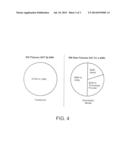
[0016] FIG. 4 is a graphical illustration of payment scenarios for a traditional utility model compared to the utility financial model described with reference to FIGS. 1-3.
DETAILED DESCRIPTION
[0017] Exemplary embodiments will be described below with reference to the accompanying drawings. It should be understood that the following description is intended to describe exemplary embodiments of the invention, and not to limit the invention.
[0018] FIG. 1 illustrates an exemplary application of a utility financial model. In this model, a lighting technology 102 replaces traditional industrial/commercial light fixtures on a one for one basis within a commercial or industrial setting 104. The lighting technology 102 can be new, more efficient lighting fixtures; new non-utility light providers (e.g., sunlight); or a combination of utility-based and non-utility based lighting. An exemplary impact is a 50% reduction in base load energy use and higher quality light. With additional controls, the technology may provide an additional 25%-50% in instantaneous peak load capacity relief. In addition to the lighting technology installation, a metering system 106 is installed to document and verify the capacity relief. A new utility rate is set for the commercial or industrial setting 104 based on the return needed and the kilowatt reduction experienced. In an exemplary embodiment, the metering system 106 provides real-time utility usage data such that the metering of power usage is absolute.
[0019] Installation of the lighting technology 102 can be paid for utilizing a reduced unit-based payment scheme where one or more payments are made by the consumer. Payments are tied to units of utility reduction rather than time. As such, the financial model is not a lease of equipment. The model is a purchase of use or throughput that uses a reduced utility rate for calculation of payment due to increased efficiencies from the new lighting technology 102. The payments can be over time or in one lump sum.
[0020] FIG. 2 illustrates a flow diagram depicting operations performed in the utility financial model of FIG. 1. Additional, fewer, or different operations may be performed depending on the particular implementation. In an operation 210, traditional light fixtures in a facility are replaced on a one for one basis with new more efficient fixtures. As such, each lighting fixture is replaced by another light fixture, rather than two light fixtures being replaced by one light fixture. In alternative embodiments, a certain number of exiting lights are replaced by one new light fixture. In yet another embodiment, natural lighting features (e.g., sunlight) are utilized in conjunction with new utility-based features. In an operation 220, a utility meter is installed at the facility to verify the relief in utility capacity resulting from the installation of the new fixtures. In one embodiment, the metering is done using a utility-grade meter. Metering devices can also include communication components to communicate utility information to a remote location. In an operation 230, aggregate displaced capacity is determined based on information about the facility where new fixtures are installed and the amount of utility capacity relief. The aggregate displaced capacity can provide the data necessary to determine pollution allowances, pollution credits earned, and financial savings for the facility. In an operation 240, blocks of displaced energy generation are sold. For example, displaced energy can be sold on a market or to the original utility company.
[0021] By way of example, replacing traditional technology with the installation of 4100 units of new technology can provide one (1) megawatt of base load capacity relief to the electrical system. The system creates blocks of displaced generation that can be sold to energy providers and public utilities in any increment of megawatt capacity. The utility or energy provider realizes capacity gains at a much faster rate with this system than with the traditional methods of capacity expansion. The capacity gains are realized immediately upon installation of the system, instead of four to five years in the future as with the construction of a traditional utility generation facility.
[0022] In addition to the increase in capacity gains created, the system also generates a number of valuable ancillary effects that benefit the greater community as a whole. For example, the system provides capacity relief without building increased generation; thus, it provides a substantial degree of environmental pollutant relief. Furthermore, it has been documented that improved lighting systems increase worker productivity, reduce employee sick time, and increase product quality, all of which benefit firms. Another advantage of the system is that it does not sell lights or conservation, rather it sells aggregated, displaced capacity to energy providers and public utilities.
[0023] A wide range of different traditional technologies can be replaced using the new technology. For example, the existing high intensity discharge (HID) lighting market in North America has been estimated to be 400,000,000 HID fixtures. Therefore, retrofitting the existing North American HID replacement market with the new technology included in the utility financial model can provide 97,560 MW of baseload capacity.
[0024] To address some of the impacts of the utility financial model on the economic development of a region, one must investigate the multiplier effect associated with the use of the model and the construction of a traditional generating facility. The multiplier effect refers to the additional income generated by an increase in planned investment/spending. In other words, a multiplier of 2 would imply that every $1 increase in planned investment would eventually generate $2 in income for the region's economy. The additional income is generated by the additional jobs and demand generated by the increased investment, which translates into greater disposable income for the region. The multiplier effect of an increased spending has three components: direct effects, indirect effects and induced effects. Direct effects include the increase in regional income associated with the workers and materials required to construct a traditional power plant or the installation of the exemplary model. Indirect effects include the increase in regional income associated with the workers, raw materials, or components required for the construction of a traditional power plant or the installation of the model to the end-use firms. Induced effects include the increase in regional income associated with the increase in demand for goods and services from regional firms associated with the increased disposable income in the region.
[0025] When investigating the multiplier effects of investing in a traditional power plant or the utility financial model, one must look at two separate multipliers: (1) the general goods and services multiplier that assesses the impact of traditional plant construction and (2) the installation of the utility financial model. The U.S. Department of Energy's general economic multiplier of 2.06 per $1 invested is employed to assess the impact of investment in traditional plant construction. The U.S. Department of Energy's energy efficiency investment multiplier of 2.32 per $1 invested is employed to assess the impact of the installation of the utility financial model. The energy efficiency investment multiplier is greater because spending on energy efficiency initiatives (like the utility financial model) has a greater impact on the regional economy than traditional plant construction. In other words, a dollar invested in traditional generating capacity will generate $2.06 in income for the local economy, while an investment of $1 in the utility financial model will generate $2.32 of income for the local economy.
[0026] The following discussion details the annual impact of saving 97,560 MW using the utility financial model versus the construction of 97,560 MW of traditional generating capacity. There are capital cost savings of $425 million based on the difference in capital costs: $925 million (traditional) and $500 million (new model). Cost savings with the new model include O&M and fuel costs of $22.0 million per year; distribution costs of $660,000 per year; and transmission costs of $660,00 per year. The avoided energy costs associated with the installation of the new model, $23.32 million, can be calculated as the sum of O&M and fuel costs, distribution costs, and transmission losses. The investment savings (amperage savings) is $100.3 million.
[0027] The multiplier impact of implementing the new model can be summarized as follows:
TABLE-US-00001 Traditional Generation: $1.91 billion Investment With Multiplier Generation: $925 million $1.91 billion Total New Model: $2.04 billion Investment/Savings With Multiplier New Model Impact: $500 million $1.16 billion Capital Differential: $425 billion $0.88 billion Final Multiplier Impact: Total New Model - Total Generation = $130 million
[0028] Therefore, if $925 million spent on traditional capacity initiatives were invested in the new model, rather than building 500 Megawatts of coal-fired facility, an additional $130 million would be generated in multiplier effects for the state of Wisconsin, for example.
[0029] The additional flow-through effects for the regional economy can be detailed as follows:
TABLE-US-00002 Multiplier Impact: $130 million O&M and Fuel Cost Multiplier: $43.9 million Transmission and Distribution Losses Multiplier: $2.72 million Total Impact: $176.6 million
[0030] The multiplier effect includes the $500 million spent on the initiative times the 2.32 energy efficiency multiplier and, since the new model requires $425 million less in capital investments, these funds are freed up to be re-invested in the economy and will have the general economy multiplier effect of 2.06. Since the new model does not require spending on O&M and fuel costs ($22.0 million), these savings can be reinvested into the economy and generate income with the general multiplier. Since the new model does not involve the transmission and distribution losses associated with a traditional generation system ($1.32 million per year), these savings can be reinvested into the economy and generate income with the general multiplier.
[0031] The analysis above suggests that the installation of 500 Megawatts using the utility financial model described herein on a nationwide basis will provide an additional $176.6 million increase in income where it is installed due to capital cost savings, investment savings, O&M cost savings, fuel cost savings multiplier, and distribution cost savings multiplier. Similarly, if 97,560 MW were installed on a nationwide basis, the utility financial model would provide an additional $60.3 billion increase in income where it is installed due to capital cost savings, investment savings, O&M cost savings, fuel cost savings multiplier, and distribution cost savings multiplier.
[0032] It should be noted these flow through effects capture the savings each customer received through the use of the utility financial model in their facilities. The reduction in energy consumption delivered by the utility financial model technologies is captured in the O&M and fuel cost savings. To see this, consider the following: for a one-customer market, the energy savings associated with the installation of the utility financial model would amount to the required reduction in energy generation for the utility.
[0033] FIG. 3 illustrates a flow diagram depicting operations performed in the establishment of a new utility rate after introducing a new technology. Additional, fewer, or different operations may be performed depending on the particular implementation. In an operation 310, a figure for kilowatt (kW) power reduction is obtained. This power reduction quantifies the reduction in load achieved by the new technology. In an operation 320, a time component for use of the technology is imposed such that the power reduction can be represented in kilowatt hours (kWh). The time component can indicate actual usage of the new technology. In the case of a warehouse where a light fixture is on 24 hours a day, year round, this time component is added to the power reduction. In contrast, some fixtures may only be used for a certain fraction of time.
[0034] In an operation 330, fixed and variable costs for the technology change are assessed to determine a return needed to re-pay associated costs. Fixed costs can include equipment costs and installation fees. Variable costs can include maintenance fees. In an operation 340, a new utility rate for the facility having the technology change is calculated. The new utility rate is a function of the power reduction over the return needed from the technology change. By way of example, a new technology may reduce a facility's utility rate from 8 per fixture per hour to 2.5 . The new utility rate is not a performance based reduction based on utility usage. Rather, the new utility rate considers power reduction and an apportionment of the return needed to recoup costs for installation of the new technology. As such, utility consumers can benefit from a new technology without a large upfront expense. Consumers repay the installation costs in a functional calculation involving the resulting power reduction.
[0035] FIG. 4 illustrates payment scenarios for a traditional utility model compared to the exemplary utility financial model described herein. The traditional model results in a payment scheme in which 100% of utility charges are paid to the utility company each year. For example, 500 fixtures running 24 hours a day 7 days a week having a fee of 5 per kWh results in $100k per year paid to the utility company.
[0036] The exemplary utility financial model results in a payment scenario which includes guaranteed cash flow to the utility consumer. In the example of 500 fixtures mentioned above, $50k is paid to the utility company, $30k is paid to the company providing the new technology, and $20k is saved by the utility consumer as guaranteed cash flow. At the end of five years, the utility consumer is ahead by $100k. At the end of a certain period of time when the technology change costs are repaid, the utility consumer no longer pays the new technology provider, enabling the consumer to save even more additional money.
[0037] In an alternative embodiment, the utility consumer makes a one time cash payment based on a calculation involving the reduced kWh. Payments for the new technology installation are tied to units and not to time.
[0038] Advantageously, implementation of a new technology using the exemplary utility financial model described herein reduces or eliminates technological and financial risk for the consumer. Further, the consumer is assured positive cash flow and is provided the measurement capabilities required for emission credits. Such emissions credits can be sold in the open market or on an exchange like the Chicago Climate Exchange, Inc.
[0039] The word "exemplary" is used herein to mean serving as an example, instance, or illustration. Any aspect or design described herein as "exemplary" is not necessarily to be construed as preferred or advantageous over other aspects or designs. Further, for the purposes of this disclosure and unless otherwise specified, "a" or "an" means "one or more."
[0040] The foregoing description of exemplary embodiments have been presented for purposes of illustration and description. It is not intended to be exhaustive or to limit the present invention to the precise form disclosed, and modifications and variations are possible in light of the above teachings or may be acquired from practice of the present invention. The embodiments were chosen and described in order to explain the principles of the present invention and its practical application to enable one skilled in the art to utilize the present invention in various embodiments and with various modifications as are suited to the particular use contemplated.
User Contributions:
Comment about this patent or add new information about this topic:
Images included with this patent application:
 |  |
 |
| New patent applications in this class: | |
| Date | Title |
|---|---|
| 2022-05-05 | Method of executing orders using an electronic forum |
| 2022-05-05 | System and method for dynamically managing message flow |
| 2022-05-05 | Compression of an exchange traded derivative portfolio |
| 2022-05-05 | Electronic trading system and data concealment method for electronic trading system |
| 2022-05-05 | Multi-faceted trading education |
| New patent applications from these inventors: | |
| Date | Title |
|---|---|
| 2015-07-30 | Outdoor lighting fixtures control systems and methods |
| 2015-03-05 | Lighting systems and methods for displacing energy consumption using natural lighting fixtures |
| 2014-11-20 | System and method for supporting and leveling a light fixture |
| 2014-06-26 | System and method for reducing peak and off-peak electricity demand by monitoring, controlling and metering lighting in a facility |
| Top Inventors for class "Data processing: financial, business practice, management, or cost/price determination" | |
| Rank | Inventor's name |
|---|---|
| 1 | Royce A. Levien |
| 2 | Robert W. Lord |
| 3 | Mark A. Malamud |
| 4 | Adam Soroca |
| 5 | Dennis Doughty |