Patent application title: SYSTEM AND METHOD FOR CATHETER STEERING AND OPERATION
Inventors:
Chester Whiseant (Marysville, CA, US)
Assignees:
Volcano Corporation
IPC8 Class: AA61M2501FI
USPC Class:
606 33
Class name: Instruments electrical application electromagnetic wave irradiation
Publication date: 2014-06-26
Patent application number: 20140180268
Abstract:
The invention generally relates to intravascular intervention catheters
and provides catheters for performing an intravascular procedure that use
a computer to control an operation at the end of the catheter. The
computer can process image data to determine where the important features
are within a patient's vessels. The catheter can include imaging devices,
steering devices, ablation mechanisms, or a combination thereof. By
referencing the precisely-calculated location of the important features,
the computer can provides signals that can be used by a control device
(such as a set of servomotors for navigation) to operate the mechanisms
at the catheter tip. Thus the catheter can be steered or an ablation
mechanism can be operated or be prevented from operating depending on a
detected location of the catheter.Claims:
1. A system for performing an intravascular procedure, the system
comprising: a catheter configured for insertion into a blood vessel; an
imaging device at a distal portion of the catheter and configured to
capture an image of the vessel; a computer system coupled to the imaging
device and operable to detect a feature in the vessel and provide a
signal to guide the catheter; and a control device operable to receive
the signal and cause the catheter to perform an operation.
2. The system of claim 1, wherein the operation comprises moving away from a wall of the vessel.
3. The system of claim 1, wherein the operation comprises steering the catheter into a branch of a bifurcated vessel.
4. The system of claim 1, wherein the operation comprises introducing a curve into the catheter based on a file stored in memory in the computer.
5. The system of claim 1, wherein the operation comprises ablation of plaque.
6. The system of claim 1, further configured to automatically detect a border within the vessel.
7. The system of claim 6, further comprising an ablation mechanism.
8. The system of claim 7, further configured to prevent any ablation operations within a determined distance of the detected border.
9. The system of claim 7, wherein the ablation mechanism comprises a transmitter for electromagnetic waves.
10. The system of claim 1, wherein the operation comprises an alternation between image capture and treatment delivery.
11. A method for performing an intravascular procedure, the method comprising: inserting a catheter into a blood vessel; capturing an image of the vessel with an imaging device on the catheter; detecting, with a computer system coupled to the imaging device, a feature in the vessel and providing a signal to guide the catheter; receiving the signal at a control device coupled to the catheter; and causing the catheter to perform an operation.
12. The method of claim 11, wherein the operation comprises moving away from a wall of the vessel.
13. The method of claim 11, wherein the operation comprises steering the catheter into a branch of a bifurcated vessel.
14. The method of claim 11, wherein the operation comprises introducing a curve into the catheter based on a file stored in memory in the computer.
15. The method of claim 11, wherein the operation comprises ablation of plaque.
16. The method of claim 11, further comprising automatically detecting a border within the vessel.
17. The method of claim 16, further comprising using an ablation mechanism to ablate plaque.
18. The method of claim 17, further comprising preventing any ablation operations within a determined distance of the detected border.
19. The method of claim 17, wherein the ablation mechanism comprises a transmitter for electromagnetic waves.
20. The method of claim 11, wherein the operation comprises an alternation between image capture and treatment delivery.
Description:
CROSS-REFERENCE TO RELATED APPLICATIONS
[0001] This application claims the benefit of, and priority to, U.S. Provisional Application Ser. No. 61/745,321, filed Dec. 21, 2012, the contents of which are incorporated by reference herein in its entirety.
FIELD OF THE INVENTION
[0002] The invention generally relates to intravascular intervention catheters and systems and methods for guiding catheter operations.
BACKGROUND
[0003] Some people are at risk of having a heart attack or stroke due to fatty plaque buildups in their arteries that restrict the flow of blood or even break off and block the flow of blood completely. A number of intravascular procedures have the potential to treat those plaque buildups. For example, angioplasty involves delivering a balloon or a stent to open up the constricted blood vessel. This procedure involves inserting a thin catheter into the patient's vessel and navigating it to the affected site.
[0004] Where the plaque has built up to the point that it effectively closes off the vessel, the affected site is sometimes referred to as a chronic total occlusion. Such an occlusion can be treated by a catheter with a mechanism at the tip that is designed to ablate the plaque, opening a hole through the occlusion, allowing the person's blood to flow and carry oxygen and nutrients throughout the body.
[0005] Using a catheter in an intravascular intervention to treat plaque buildup carries some risks and difficulties. The blood vessels define a convoluted and intricate network. Simply navigating a catheter to the correct site from outside the body can be very difficult. Even where a branch in the vessel can be seen from outside of the body by x-ray, steering a catheter down the right branch can be a significant challenge. Using an ablation mechanism to cut through an occlusion requires the utmost precision. Ablation can use lasers, RF waves, or mechanical cutters to cut up the plaque, and those cutter mechanisms operate within fractions of a millimeter of the walls of a person's blood vessels. It requires exacting precision to ablate plaque properly.
SUMMARY
[0006] The invention provides catheters for performing an intravascular procedure that use a computer to control an operation at the end of the catheter. The computer can process image data captured via the catheter to determine, with precision, where the important features are within a patient's vessels. For example, a computer can automatically detect the boundaries of plaque and the edges of blood vessels. A catheter can include imaging devices, steering devices, ablation mechanisms, or a combination thereof. The computer can determine where the catheter is and what is intended to be done. By referencing the precisely-calculated location of the important features, the computer can provides signals that can be used by a control device (such as a set of servomotors for navigation) to operate the mechanisms at the catheter tip. Thus the catheter can be steered down the correct branch of a split, or an ablation mechanism can be operated only when in contact with plaque and can be prevented from operating when too close to a vessel wall. Even where, for example, the ablation mechanism is to be controlled manually by a doctor, the computer can offer an important safety override by turning off the ablation mechanism (e.g., the laser or cutter) if the tip is too close to healthy tissue. Since the computer and control device offer precision control over steering and operations, a catheter of the invention can be used in an intravascular treatment with greater ease and reliability. Thus, a greater number of people can be treated for arterial plaque, and life-threatening heart attacks and strokes can be prevented.
[0007] In certain aspects, the invention provides a system for performing an intravascular procedure. The system includes a catheter for insertion into a blood vessel, an imaging device at a distal portion of the catheter, and a computer system coupled to the imaging device. The computer is operable to detect a feature in the vessel and provide a signal to guide the catheter. The system includes a control device to receive the signal and cause the catheter to perform an operation. The operation may be moving the catheter away from a wall of the vessel, steering the catheter into a branch of a bifurcated vessel, introducing a curve into the catheter based on a file stored in memory in the computer, the ablation of plaque, any other operation, or a combination thereof. The computer may be configured to automatically detect a border within the vessel. In some embodiments, the system includes an ablation mechanism, such as a cutter tip or an RF transmitter. The computer and control device can work to prevent any ablation operations within a determined distance of the detected border. Since RF waves, while being used for occlusion ablation, can interfere with intravascular imaging, the computer and the control device can operate to cause the system to alternate between image capture and treatment delivery--i.e., view the vessel, ablate the occlusion, view the vessel, ablate the occlusion, etc.
[0008] In related aspects, the invention provides a method for performing an intravascular procedure that includes inserting a catheter for insertion into a blood vessel, taking a picture of the vessel with an imaging device on the catheter, and detecting a feature in the vessel using a computer. The computer is used to provide a signal to guide the catheter. The signal is received at a control device coupled to the catheter, and the control device operates to cause the catheter to perform an operation. The method may include moving the catheter away from a wall of the vessel, steering the catheter into a branch of a bifurcated vessel, introducing a curve into the catheter based on a file stored in memory in the computer, ablating plaque or an occlusion, automatically detecting a border within the vessel, other operations, or a combination thereof, all under the guidance of software in the computer system. Exemplary functions that can be controlled by the computer software can include preventing any ablation operations within a determined distance of the detected border, i.e., for patient safety.
BRIEF DESCRIPTION OF THE DRAWINGS
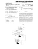
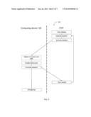
[0009] FIG. 1 illustrates an imaging system according to certain embodiments.
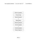
[0010] FIG. 2 diagrams steps by which methods of embodiments of the invention operate.
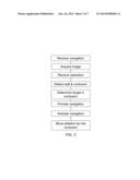
[0011] FIG. 3 diagrams an embodiment of the invention.
[0012] FIG. 4 illustrates coupled interactions between a user and a computing device.
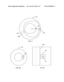
[0013] FIG. 5 illustrates a display of an imaging system showing a luminal border.
[0014] FIG. 6A depicts a defined area around point on a tomographic view.
[0015] FIG. 6B shows a corresponding B-scan.
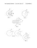
[0016] FIG. 7 depicts an exemplary IVUS image of a vascular object.
[0017] FIG. 8 illustrates a step in use of a border-detection algorithm.
[0018] FIG. 9 shows use of multiple 2D images to produce a 3D image of a tubular object.
[0019] FIG. 10 is an extrapolation of an identified control point to another IVUS image.
[0020] FIG. 11 illustrates a luminal border and a medial-adventitial border.
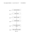
[0021] FIG. 12 diagrams a method of controlling an intravascular operation.
DETAILED DESCRIPTION
[0022] The present invention provides a system and method of using an intravascular imaging system that includes using a computer to control operations such as steering or ablation performed with a catheter. Systems and methods of the invention operate with intravascular imaging systems such as, for example, intravascular ultrasound (IVUS), optical coherence tomography (OCT), combined optical-acoustic imaging, others, or a combination thereof.
[0023] FIG. 1 illustrates an exemplary imaging system 101 in accordance with one embodiment of the present invention. System 101 includes console 110 electrically connected to a computing device 120 and a distal tip 114 via a catheter 112 and patient interface module 105. The distal tip 114 is inserted into a blood vessel of a patient lying etherized upon a table and used to gather image data (i.e., blood-vessel data, or data that can be used to identify the shape of a blood vessel, its density, its composition, etc.). The image data are then provided to (or acquired by) the computer device 120, where they are used to produce an image of the vessel. Systems for IVUS suitable for use with the invention are discussed in U.S. Pat. No. 5,771,895; U.S. Pub. 2009/0284332; U.S. Pub. 2009/0195514; U.S. Pub. 2007/0232933; and U.S. Pub. 2005/0249391, the contents of each of which are hereby incorporated by reference in their entirety.
[0024] While system 101 is described for illustrative purposes as an IVUS system, it will be appreciated that detection methods described herein can operate with a 3D data set collected via other imaging modalities as well. For example, the catheter of the invention includes may include any imaging assembly may be used with devices and methods of the invention, such as optical-acoustic imaging apparatus, intravascular ultrasound (IVUS) or optical coherence tomography (OCT).
[0025] In some embodiments, the imaging assembly is an IVUS imaging assembly. The imaging assembly can be a phased-array IVUS imaging assembly, a pull-back type IVUS imaging assembly, including rotational IVUS imaging assemblies, or an IVUS imaging assembly that uses photoacoustic materials to produce diagnostic ultrasound and/or receive reflected ultrasound for diagnostics. IVUS imaging assemblies and processing of IVUS data are described for example in Yock, U.S. Pat. Nos. 4,794,931, 5,000,185, and 5,313,949; Sieben et al., U.S. Pat. Nos. 5,243,988, and 5,353,798; Crowley et al., U.S. Pat. No. 4,951,677; Pomeranz, U.S. Pat. No. 5,095,911, Griffith et al., U.S. Pat. No. 4,841,977, Maroney et al., U.S. Pat. No. 5,373,849, Born et al., U.S. Pat. No. 5,176,141, Lancee et al., U.S. Pat. No. 5,240,003, Lancee et al., U.S. Pat. No. 5,375,602, Gardineer et at., U.S. Pat. No. 5,373,845, Seward et al., Mayo Clinic Proceedings 71(7):629-635 (1996), Packer et al., Cardiostim Conference 833 (1994), "Ultrasound Cardioscopy," Eur. J.C.P.E. 4(2):193 (June 1994), Eberle et al., U.S. Pat. No. 5,453,575, Eberle et al., U.S. Pat. No. 5,368,037, Eberle et at., U.S. Pat. No. 5,183,048, Eberle et al., U.S. Pat. No. 5,167,233, Eberle et at., U.S. Pat. No. 4,917,097, Eberle et at., U.S. Pat. No. 5,135,486, and other references well known in the art relating to intraluminal ultrasound devices and modalities. All of these references are incorporated by reference herein in their entirety.
[0026] IVUS imaging is widely used in interventional cardiology as a diagnostic tool for assessing a diseased vessel, such as an artery, within the human body to determine the need for treatment, to guide an intervention, and/or to assess its effectiveness. An IVUS device including one or more ultrasound transducers is introduced into the vessel and guided to the area to be imaged. The transducers emit and then receive backscattered ultrasonic energy in order to create an image of the vessel of interest. Ultrasonic waves are partially reflected by discontinuities arising from tissue structures (such as the various layers of the vessel wall), red blood cells, and other features of interest. Echoes from the reflected waves are received by the transducer and passed along to an IVUS imaging system. The imaging system processes the received ultrasound echoes to produce a 360 degree cross-sectional image of the vessel where the device is placed.
[0027] There are two general types of IVUS devices in use today: rotational and solid-state (also known as synthetic aperture phased array). For a typical rotational IVUS device, a single ultrasound transducer element is located at the tip of a flexible driveshaft that spins inside a plastic sheath inserted into the vessel of interest. The transducer element is oriented such that the ultrasound beam propagates generally perpendicular to the axis of the device. The fluid-filled sheath protects the vessel tissue from the spinning transducer and driveshaft while permitting ultrasound signals to propagate from the transducer into the tissue and back. As the driveshaft rotates, the transducer is periodically excited with a high voltage pulse to emit a short burst of ultrasound. The same transducer then listens for the returning echoes reflected from various tissue structures. The IVUS imaging system assembles a two dimensional display of the vessel cross-section from a sequence of pulse/acquisition cycles occurring during a single revolution of the transducer. Suitable rotational IVUS catheters include, for example the REVOLUTION 45 MHz catheter (offered by the Volcano Corporation).
[0028] In contrast, solid-state IVUS devices carry a transducer complex that includes an array of ultrasound transducers distributed around the circumference of the device connected to a set of transducer controllers. The transducer controllers select transducer sets for transmitting an ultrasound pulse and for receiving the echo signal. By stepping through a sequence of transmit-receive sets, the solid-state IVUS system can synthesize the effect of a mechanically scanned transducer element but without moving parts. The same transducer elements can be used to acquire different types of intravascular data. The different types of intravascular data are acquired based on different manners of operation of the transducer elements. The solid-state scanner can be wired directly to the imaging system with a simple electrical cable and a standard detachable electrical connector.
[0029] The transducer subassembly can include either a single transducer or an array. The transducer elements can be used to acquire different types of intravascular data, such as flow data, motion data and structural image data. For example, the different types of intravascular data are acquired based on different manners of operation of the transducer elements. For example, in a gray-scale imaging mode, the transducer elements transmit in a certain sequence one gray-scale IVUS image. Methods for constructing IVUS images are well-known in the art, and are described, for example in Hancock et al. (U.S. Pat. No. 8,187,191), Nair et al. (U.S. Pat. No. 7,074,188), and Vince et al. (U.S. U.S. Pat. No. 6,200,268), the content of each of which is incorporated by reference herein in its entirety. In flow imaging mode, the transducer elements are operated in a different way to collect the information on the motion or flow. This process enables one image (or frame) of flow data to be acquired. The particular methods and processes for acquiring different types of intravascular data, including operation of the transducer elements in the different modes (e.g., gray-scale imaging mode, flow imaging mode, etc.) consistent with the present invention are further described in U.S. patent application Ser. No. 14/037,683, the content of which is incorporated by reference herein in its entirety.
[0030] The acquisition of each flow frame of data is interlaced with an IVUS gray scale frame of data. Operating an IVUS catheter to acquire flow data and constructing images of that data is further described in O'Donnell et al. (U.S. Pat. No. 5,921,931), U.S. Provisional Patent Application No. 61/587,834, and U.S. Provisional Patent Application No. 61/646,080, the content of each of which is incorporated by reference herein its entirety. Commercially available fluid flow display software for operating an IVUS catheter in flow mode and displaying flow data is CHROMAFLOW (IVUS fluid flow display software offered by the Volcano Corporation).
[0031] Suitable phased array imaging catheters include Volcano Corporation's EAGLE EYE Platinum Catheter, EAGLE EYE Platinum Short-Tip Catheter, and EAGLEEYE Gold Catheter.
[0032] Additionally or alternatively, system 101 may be configured to perform optical coherence tomography (OCT). In OCT, a light source delivers a beam of light to an imaging device to image target tissue. Within the light source is an optical amplifier and a tunable filter that allows a user to select a wavelength of light to be amplified. Wavelengths commonly used in medical applications include near-infrared light, for example between about 800 nm and about 1700 nm.
[0033] Generally, there are two types of OCT systems, common beam path systems and differential beam path systems, that differ from each other based upon the optical layout of the systems. A common beam path system sends all produced light through a single optical fiber to generate a reference signal and a sample signal whereas a differential beam path system splits the produced light such that a portion of the light is directed to the sample and the other portion is directed to a reference surface. Common beam path interferometers are further described for example in U.S. Pat. No. 7,999,938; U.S. Pat. No. 7,995,210; and U.S. Pat. No. 7,787,127, the contents of each of which are incorporated by reference herein in its entirety.
[0034] In a differential beam path system, amplified light from a light source is input into an interferometer with a portion of light directed to a sample and the other portion directed to a reference surface. A distal end of an optical fiber is interfaced with a catheter for interrogation of the target tissue during a catheterization procedure. The reflected light from the tissue is recombined with the signal from the reference surface forming interference fringes (measured by a photovoltaic detector) allowing precise depth-resolved imaging of the target tissue on a micron scale. Exemplary differential beam path interferometers are Mach-Zehnder interferometers and Michelson interferometers. Differential beam path interferometers are further described for example in U.S. Pat. No. 7,783,337; U.S. Pat. No. 6,134,003; and U.S. Pat. No. 6,421,164, the contents of each of which are incorporated by reference herein in its entirety. OCT systems and methods are described in U.S. Pub. 2011/0152771; U.S. Pub. 2010/0220334; U.S. Pub. 2009/0043191; U.S. Pub. 2008/0291463; and U.S. Pub. 2008/0180683, the contents of each of which are hereby incorporated by reference in their entirety.
[0035] Aspects of the invention may obtain imaging data from an OCT system, including OCT systems that operate in either the time domain or frequency (high definition) domain. Basic differences between time-domain OCT and frequency-domain OCT is that in time-domain OCT, the scanning mechanism is a movable minor, which is scanned as a function of time during the image acquisition. However, in the frequency-domain OCT, there are no moving parts and the image is scanned as a function of frequency or wavelength.
[0036] In time-domain OCT systems an interference spectrum is obtained by moving the scanning mechanism, such as a reference minor, longitudinally to change the reference path and match multiple optical paths due to reflections within the sample. The signal giving the reflectivity is sampled over time, and light traveling at a specific distance creates interference in the detector. Moving the scanning mechanism laterally (or rotationally) across the sample produces two-dimensional and three-dimensional images.
[0037] In frequency domain OCT, a light source capable of emitting a range of optical frequencies excites an interferometer, the interferometer combines the light returned from a sample with a reference beam of light from the same source, and the intensity of the combined light is recorded as a function of optical frequency to form an interference spectrum. A Fourier transform of the interference spectrum provides the reflectance distribution along the depth within the sample.
[0038] Several methods of frequency domain OCT are described in the literature. In spectral-domain OCT (SD-OCT), also sometimes called "Spectral Radar" (Optics letters, Vol. 21, No. 14 (1996) 1087-1089), a grating or prism or other means is used to disperse the output of the interferometer into its optical frequency components. The intensities of these separated components are measured using an array of optical detectors, each detector receiving an optical frequency or a fractional range of optical frequencies. The set of measurements from these optical detectors forms an interference spectrum (Smith, L. M. and C. C. Dobson, Applied Optics 28: 3339-3342), wherein the distance to a scatterer is determined by the wavelength dependent fringe spacing within the power spectrum. SD-OCT has enabled the determination of distance and scattering intensity of multiple scatters lying along the illumination axis by analyzing a single the exposure of an array of optical detectors so that no scanning in depth is necessary. Typically the light source emits a broad range of optical frequencies simultaneously.
[0039] Alternatively, in swept-source OCT, the interference spectrum is recorded by using a source with adjustable optical frequency, with the optical frequency of the source swept through a range of optical frequencies, and recording the interfered light intensity as a function of time during the sweep. An example of swept-source OCT is described in U.S. Pat. No. 5,321,501.
[0040] Generally, time domain systems and frequency domain systems can further vary in type based upon the optical layout of the systems: common beam path systems and differential beam path systems. A common beam path system sends all produced light through a single optical fiber to generate a reference signal and a sample signal whereas a differential beam path system splits the produced light such that a portion of the light is directed to the sample and the other portion is directed to a reference surface. Common beam path systems are described in U.S. Pat. No. 7,999,938; U.S. Pat. No. 7,995,210; and U.S. Pat. No. 7,787,127 and differential beam path systems are described in U.S. Pat. No. 7,783,337; U.S. Pat. No. 6,134,003; and U.S. Pat. No. 6,421,164, the contents of each of which are incorporated by reference herein in its entirety.
[0041] In yet another embodiment, the imaging catheter for use in methods of the invention is an optical-acoustic imaging apparatus. Optical-acoustic imaging apparatus include at least one imaging element to send and receive imaging signals. In one embodiment, the imaging element includes at least one acoustic-to-optical transducer. In certain embodiments, the acoustic-to-optical transducer is an Fiber Bragg Grating within an optical fiber. In addition, the imaging elements may include the optical fiber with one or more Fiber Bragg Gratings (acoustic-to-optical transducer) and one or more other transducers. The at least one other transducer may be used to generate the acoustic energy for imaging. Acoustic generating transducers can be electric-to-acoustic transducers or optical-to-acoustic transducers.
[0042] Fiber Bragg Gratings for imaging provides a means for measuring the interference between two paths taken by an optical beam. A partially-reflecting Fiber Bragg Grating is used to split the incident beam of light into two parts, in which one part of the beam travels along a path that is kept constant (constant path) and another part travels a path for detecting a change (change path). The paths are then combined to detect any interferences in the beam. If the paths are identical, then the two paths combine to form the original beam. If the paths are different, then the two parts will add or subtract from each other and form an interference. The Fiber Bragg Grating elements are thus able to sense a change wavelength between the constant path and the change path based on received ultrasound or acoustic energy. The detected optical signal interferences can be used to generate an image using any conventional means.
[0043] Exemplary optical-acoustic imaging assemblies are disclosed in more detail in U.S. Pat. Nos. 6,659,957 and 7,527,594, 7,245.789, 7447,388, 7,660,492, 8,059,923 and in U.S. Patent Publication Nos. 2008/0119739, 2010/0087732 and 2012/0108943.
[0044] In certain embodiments, the detection methods described herein can operate with a 3D data set based on co-registered sets of data captured by a variety of modalities, imaging or otherwise. For example, systems consistent with the present invention may be configured to co-register image data captured by the catheter with other data captured by additional modalities. Co-registration generally refers to any method of re-aligning images, and in particular aligning or overlaying images from different modalities. Co-registration is often used to overlay structural and functional images as well as link functional scans to anatomical scans. Co-registration generally is described in, for example, in U.S. Pat. Nos. 7,930,104; and 8,298,147; and U.S. patent application No. 13/388,932, each of which is incorporated herein by reference in its entirety.
[0045] For example, in one embodiment, angiogram image data is obtained simultaneously with the imaging data obtained from the imaging catheter of the present invention. In such embodiments, the imaging catheter may include one or more radiopaque labels that allow for co-locating image data with certain positions on a vasculature map generated by an angiogram. Co-locating intraluminal image data and angiogram image data is known in the art, and described in U.S. Publication Nos. 2012/0230565, 2011/0319752, and 2013/0030295. It should be noted that any number of modalities is useful for co-registration. Furthermore, modalities suitable for co-registration include functional measurement parameters, including, but not limited to, vessel flow, vessel pressure, FFR, iFR, CFR, etc.
[0046] Systems and methods for co-registering intravascular data can be found in, for example, in U.S. Pat. Nos. 7,930,104; and 8,298,147; U.S. patent application Ser. No. 13/388,932; U.S. patent application Ser. No. 61/776,863; U.S. Provisional Appln. No. 61/776,858; U.S. patent application Ser. No. 61/777,155; U.S. patent application Ser. No. 61/777,860; U.S. patent application Ser. No. 61/779,610; and U.S. patent application Ser. No. 61/792,230, each of which is incorporated herein by reference in their entirety.
[0047] In certain embodiments, catheter 112 is a steerable catheter and optionally includes a steering mechanism and PIM 105 includes a control device operable to steer catheter 112. Catheter 112 may include any suitable steering mechanism. In some embodiments, a steering mechanism includes a plurality (e.g., 4) of extended wire reins beneath a surface of catheter 112, extending along the catheter body and disposed around it. Pulling back on any one of the reins tends to cause the tip 114 steer in a direction of the pulled-back rein. The reins may include a metal, such as stainless steel or nitinol, or any other material including, for example, a polymer, such as polytetrafluoroethylene or a plastic. A proximal end of each rein can be wound onto a spindle mounted on an axle of a servomotor. Each motor may be wired to a chip coupled to computer device 120. A program in computer device 120 can drive each motor according to a pattern that causes the motors to wind up the reins, thereby pulling them back, and steering catheter 112. In certain embodiments, a steering mechanism includes the use of an electroactive polymer disposed within catheter 112 (e.g., substantially as just described for reins). Contraction of the polymers is controlled by computer 120 being used to cause the application of a potential difference across individual ones of the electroactive polymers. By referring to information, commands, or both, in a program, computer 120 can steer catheter 112 via the electroactive polymer.
[0048] In some embodiments, a distal tip 114 includes a device such as an IVUS imaging device, an ablation mechanism, steering mechanics, or a combination thereof. Where, for example, an imaging device is included, catheter 112 can be used to capture an image of a patient's vessel.
[0049] In certain embodiments, an ablation mechanism is included to open a hole through a chronic total occlusion. In some embodiments, the invention provides systems and methods for treating a chronic total occlusion. Catheter 112 can be used to bring an imaging device (e.g., such as a forward looking IVUS device) to a chronic total occlusion. Once the tip 114 is positioned appropriately, an ablation mechanism is activated. Any suitable mechanism for ablating plaque may be used. For example, RF waves can be used to ablate and break through a chronic total occlusion. Other suitable ablation mechanisms known in the art include mechanical ablation mechanisms (e.g., drills, cutter, knives, Archimedes' screws, punches, slicers, etc.), lasers, or others. In certain embodiments, computer 120 includes a processor and memory for analyzing signal captured by an imaging device. For example, computer 120 may do a virtual histology analysis on an image and determine a location of a lumen, necrotic tissue, healthy tissue, and other features within a patient's vessel. By determining where an outer border of a vessel is, where a lumen is, and other information, a computer can then determine (e.g., mathematically), where a center of vessel should be, and thus, where a center of a lumen should be. Additionally or alternatively, a computer can determine where a portion of catheter 112 (e.g., an imaging device or an ablation mechanism) presently is. Computer 120 can use this information to guide the operation of catheter 112. For example, if an ablation mechanism is within a determined distance (e.g., 0.5 mm) of a should-be center of a vessel, and is also within necrotic tissue or plaque, computer 120 can determine to operate the ablation mechanism. Computer 120 can send a signal that is received by a control device (e.g., within PIM 105) that then operates the mechanism on catheter 112. Additionally or alternatively, computer 120 can issue instructions to steer catheter 112 towards an occlusion, towards a center of a vessel, or in other desired ways (e.g., down a desired branch at a vessel bifurcation).
[0050] In certain embodiments, processor and memory systems in computer 120 are operable to receive an image, determine an outer border, determine a blockage, determine a putative healthy lumen, determine a center of a lumen, and calculate what should be a center. Using computer 120 to figure out a delta between center of lumen and what should be a center of a lumen, systems and methods of the operation can move a tool to the should-be center, or to the edge of a plaque or occlusion, and ablate the material away. In some applications, during a burst of RF energy, an imaging component will not produce a viewable image due to the interference of the RF energy. One function that can be provided by computer 120 is to alternate between imaging and blasting. This way, energy from RF blasting does not interfere with imaging operations.
[0051] Additionally, systems and methods of the invention provide important safety functionality. For example, computer 120 can issue signals that prevent any ablation operation if a device is with a certain distance from a vessel wall. As will be appreciated from the disclosure herein, the invention provides systems and methods to coordinate treatment operations as well as imaging operations, particularly through the use of computer-guided steering of an intravascular catheter.
[0052] Where IVUS is the imaging modality, IVUS data are gathered in segments, either through a rotating transducer or an array of circumferentially positioned transducers, where each segment represents an angular portion of an IVUS image. Thus, it takes a plurality of segments (or a set of IVUS data) to image an entire cross-section of a vascular object. Furthermore, multiple sets of IVUS data are typically gathered from multiple locations within a vascular object (e.g., by moving the transducer linearly through the vessel). These multiple sets of data can then be used to create a plurality of two-dimensional (2D) images or one three-dimensional (3D) image. It should be appreciated that the present invention is not limited to the use of an IVUS device (or the acquisition of IVUS data), and may further include using thermographic devices, optical devices (e.g., an optical coherence tomography (OCT) console), MRI devices, or any vascular imaging devices generally known to those skilled in the art. For example, instant automatic border detection may be provided in OCT systems such as those described in U.S. Pub. 2011/0152771; U.S. Pub. 2010/0220334; U.S. Pub. 2009/0043191; U.S. Pub. 2008/0291463; and U.S. Pub. 2008/0180683, the contents of each of which are hereby incorporated by reference in their entirety. It should further be appreciated that the computing device depicted in FIG. 1 includes, but its not limited to, personal computers or any other data-processing devices (general purpose or application specific) that are generally known to those skilled in the art.
[0053] FIG. 2 diagrams steps by which methods of embodiments of the invention operate. Catheter 112 is navigated to a target site within the vessel (e.g., by a doctor using angiographic guidance, by a computer, by the guidance offered by the imaging modality, or a combination thereof). Once the navigation is received, the system acquires an image of the vessel. Additionally, the system receives information about an intended operation (e.g., is this an ablation operation, a steering procedure, etc.). The image is then analyzed. The image data (or multiple sets thereof) are provided to (or acquired by) the computing device 120. A portion of the 3D data set may be displayed for the user on, for example, monitor 103. The display will show, in a cross section of a blood vessel, objects within a certain range of transducer 114.
[0054] One or more features are detected by computer 120 within the vessel. Vascular objects include several identifiable borders. For example, the luminal border demarcates the blood-intima interface and the medial border demarcates the external elastic membrane (the boundary between the media and adventitia).
[0055] The system uses information about the operational objective. This can be received contextually (e.g., use of an IVUS imaging catheter can signal that the operation is for imaging) or input (e.g., a doctor can turn on ablation protection, which informs the system that an ablation mechanism is to be prevented from operating within a certain distance of tissue).
[0056] In some embodiments, the detected feature will be a border. The detected border can optionally be provided as one or more lines drawn on the screen (e.g., overlaying the location of the detected border), in the form of a numerical calculation, as a file for later reference, as a diagnostic code, or a combination thereof. Preferably, information about the detected border is used within the memory of the computer to provide a signal for use in operating catheter 112. In certain embodiments, the operating signal includes navigation in the form of steering catheter 112 in an intended direction.
[0057] Once the signal is provided, navigation is activated. For example, servomotors on PIM 105 pull back on the reins and steer distal tip 114 of catheter 112. Where the objective includes an ablation operation, the control device causes this operation to happen.
[0058] Embodiments of the invention employ a feature detection program in computer 120. The feature-detection application is adapted to identify a border on a vascular image (e.g., an IVUS image). In one embodiment of the present invention, this is performed by analyzing the image data to determine certain gradients located therein. This is because borders of vascular objects can be identified by a change in pixel color (e.g., light-to-dark, dark-to-light, shade1-to-shade2, etc.).
[0059] FIG. 3 shows an embodiment of the invention for crossing a chronic total occlusion. Catheter 112 is navigated to a target site within the vessel (e.g., by a doctor using angiographic guidance, by a computer, by the guidance offered by the imaging modality, or a combination thereof). Once the navigation is received, the system acquires an image of the vessel. Additionally, the system receives information about an intended operation (e.g., is this an ablation operation, a steering procedure, etc.). The image is then analyzed. The image data (or multiple sets thereof) are provided to (or acquired by) the computing device 120. A portion of the 3D data set may be displayed for the user on, for example, monitor 103. The display will show, in a cross section of a blood vessel, objects within a certain range of transducer 114.
[0060] One or more features are detected by computer 120 within the vessel. Vascular objects that can be detected includes vessel walls and occlusions. Having detected the occlusion, computer 120 determines an ablation target within the occlusion and navigates an ablation mechanism at tip 114 of catheter 112 to the target. Once the ablation mechanism is in place, it is activated and the occlusion is ablated.
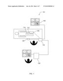
[0061] FIG. 4 illustrates the use of systems and methods of the invention to provide a safety operation in a procedure with an objective of crossing a chronic total occlusion.
[0062] An operator/user, such as a physician, views the display 103 to see images from a 3D data set. The user uses joystick 125 to navigate to an occlusion. The user then operates a trigger on the outside of the system to run the ablation mechanism.
[0063] Computing device 120 detects the occlusion as well as the wall. Based on determined parameters stored in memory, computing device 120 defines a dead zone for patient safety (e.g., no laser ablation mechanism should be operated within 0.1 mm of a vessel wall). Computing device 120 detects that the operator seeks to operate the ablation mechanism within the dead zone and overrides the ablation command. Computer 120 may further, optionally, steer catheter 112 to nudge the tip out of the dead zone. The operator may view the vessel and see that operations as determined by computer 120 have been implemented. The operator may then proceed to perform the occlusion-crossing procedure safely.
[0064] FIG. 5 illustrates, in simplified fashion, a display 131 of an imaging system showing a luminal border 320 and a medial border 310. In certain embodiments, the system uses a processor to perform an image processing operation to detect a border. A border may be detected instantly, automatically, solely in response to navigational input or cessation of navigational input, or a combination thereof. Automatically generally refers to an absence of human intervention. Where a system automatically provides a border in response to navigational input, that means that no human action other than the navigational input is required. Instant can mean simultaneously, substantially simultaneously, within a few microseconds, within about a second, or within a few seconds. Any suitable border detection algorithm can be employed. Exemplary border detection systems are discussed in U.S. Pat. No. 7,463,759; U.S. Pat. No. 6,475,149; U.S. Pat. No. 6,120,445; U.S. Pub. 2012/0226153; and U.S. Pub. 2007/0201736, the contents of which are incorporated by reference. For example, in some embodiments, the system uses a radius to detect a control point; uses the control point to define a search area; uses the search area to find a portion of a border; and uses the portion of the border to locate an entire border. Looking at FIG. 5, a first control point 22 may be taken as a point of highest contrast on an arbitrary radius 137 from the center of the screen to an edge (e.g., the "due east" radius at a theta of zero). Starting from the control point 22, system then defines an area 25 around point 22.
[0065] FIG. 6A depicts a defined area 25 around point 22. Area 25 operates as a search window. The search window area 25 may be a rectangle, circle, ellipse, polygon, or other shape. It may have a predetermined area (e.g., a certain number of pixels). In some embodiments, a size and shape of area 25 is determined by a combination of input device resolution, screen area subtended by a pixel at the particular polar coordinates, current zoom factor, usability studies, or a combination thereof. Usability studies can be performed to establish a statistical model of user repeatability and reproducibility under controlled conditions. Computer 120 may determine that all areas within, for example, 0.2 mm of border 310 are a dead zone and prevent ablation there.
[0066] FIG. 6B depicts a defined area 25 around point 22 shown in a B scan. The system searches for the border within area 25 by performing a processing operation on the corresponding data. The processing operation can be any suitable search algorithm known in the art. In some embodiments, a morphological image processing operation is used. Morphological image processing includes operations such as erosion, dilation, opening, and closing, as well as combination thereof. In some embodiments, these operations involve converting the image data to binary data giving each pixel a binary value. With pixels within area 25 converted to binary, each pixel of a feature such as a border may be black, and the background pixels will predominantly be white (or vice versa). In erosion, every pixel that is touching background is changed into a background pixel. In dilation, every background pixel that is adjacent to the non-background object pixels is changed into an object pixel. Opening is an erosion followed by a dilation, and closing is a dilation followed by an erosion. Morphological image processing is discussed in Smith, The Scientist and Engineer's Guide to Digital Signal Processing, 1997, California Technical Publishing, San Diego, Calif., pp. 436-442.
[0067] If a border is not found within area 25, area 25 can be increased and the increased area can be searched. This strategy can exploit the statistical properties of signal-to-noise ratio (SNR) by which the ability to detect an object is proportional to the square root of its area. See Smith, Ibid., pp. 432-436.
[0068] With reference to FIG. 6B, once a portion of the border is detected within area 25, the search can then be extended "upwards" and "downwards" into adjacent A-scan lines in the B-scan until the entire border is detected by the processor and its location is determined with precision. In some embodiments, image processing operations incorporate algorithms with pre-set parameters, user-set parameters, or both that optimize results and continuity of results. For example, if a line appears that is not contiguous across an entire 100% of the image (e.g., the entire extent of the B-scan or a full circle in a tomographic view), an accept or reject parameter can be established based on a percent contiguous factor. In some embodiments, lines that are contiguous across less than 75% (or 50% or 90%, depending on applications) are rejected while others are accepted.
[0069] While certain methods of using a processor to detect a feature are described above, described steps can be performed in other orders. For example, the system can apply morphological processing operations to an entire image and detect every element, or every element that satisfies a certain quality criterion. Then the system can receive use input (e.g., navigation) and respond by provided the pre-detected border. Similarly, the steps can be performed simultaneously. Using the methodologies herein, systems of the invention can provide a border detected within an image of an imaging system, such as an IVUS system, with great precision, based on a location that an operator navigates too. As discussed above, any suitable border detection process can be employed. Border detection is described, for example, in U.S. Pat. No. 8,050,478; U.S. Pat. No. 7,068,852; U.S. Pat. No. 6,491,636; U.S. Pub. 2011/0216378; and U.S. Pub. 2003/0016604, the contents of which are incorporated by reference.
[0070] FIGS. 7-12 illustrate certain embodiments, in which computing device 120 includes a plurality of applications operating thereon--i.e., a border-detection application, an extrapolation application, and an active-contour application. These applications are used to (i) identify a border and control points on a first IVUS image (i.e., any IVUS image), (ii) extrapolate the control points to a second IVUS image (i.e., another IVUS image), (iii) identify a border on the second IVUS image, and (iv) adjust the border on the second IVUS image. It should be appreciated that the number and/or location of the applications are not intended to limit the present invention, but are merely provided to illustrate the environment in which the present invention operates. Thus, for example, using a single application to perform the application functions, as discussed herein, or remotely locating at least one of the applications (in whole or in part) is within the spirit and scope of the present invention. It should further be appreciated that, while the present invention is discussed in terms of singularities (e.g., identifying a border on one IVUS image, extrapolating control points to another IVUS image, etc.), the present invention is not so limited. In fact, the present invention is particularly useful if it is used on a plurality of IVUS images (e.g., identifying borders on every fifth IVUS image, extrapolating control points from the fifth IVUS image to the next four IVUS images, etc.). It should also be appreciated that the terms "first" and "second," as those terms are used herein, are used broadly to identify any two IVUS images. Thus, the phrase "second IVUS image" may be used to identify an IVUS image distinct from a first IVUS image (as opposed to the second IVUS image in a series of IVUS images).
[0071] FIG. 7 shows a cartoon rendering of an exemplary IVUS image 20 of a vascular object. The image 20 is depicted as including a luminal border 320 and a medial border 310. On a typical IVUS grayscale image, starting from the center and working outward, the catheter will be the first light-to-dark transition. Continuing outward, the next dark-to-light transition (or gradient) identifies the luminal border (i.e., see FIG. 7, 320). The medial border can then be identified by going outward from the luminal border until the next dark-to-light transition (or gradient) is found (see FIG. 7, 310). It should be appreciated that because the IVUS image is constructed using gray-scales, it may be necessary to utilize an algorithm and/or at least one threshold value to identify precisely where the image changes from light to dark (or vice versa). However, it should further be appreciated that the present invention is not limited to any particular algorithm for identifying the aforementioned transitions, and includes all algorithms (and/or threshold values) generally known to those skilled in the art.
[0072] Once the border is identified, the border-detection algorithm is further adapted to identify at least one control point on the border. For example, with reference to FIGS. 7 and 8, the border-detection algorithm can be used to identify a plurality of control points 22 on the luminal border 320. It should be appreciated that the location and number of control points depicted in FIG. 8 are not intended to limit the present invention, and are merely provided to illustrate the environment in which the present invention may operate. In an alternate embodiment, the border-detection application is adapted to identify a border using user-identified control points. Embodiments are described in in U.S. Pat. No. 8,233,718; U.S. Pat. No. 7,978,916; and U.S. Pat. No. 6,381,350, the contents of each of which are incorporated by reference in their entirety.
[0073] Once the border and control point(s) are identified on a first vascular image, an extrapolation application is used to identify at least one control point on at least one other IVUS image. In a preferred embodiment of the present invention, this is done by extrapolating the previously identified control points to at least one other IVUS image. By doing this, multiple 2D images (or at least one 3D image) can be produced. For example, as illustrated in FIG. 9, multiple 2D images (e.g., 20, 52a-52d, etc.) are used to produce a 3D image of a tubular (e.g., vascular) object 50.
[0074] FIG. 10 illustrates how an identified control point can be extrapolated to another IVUS image. Specifically, the control points that were illustrated in FIG. 8 (i.e., 22) are extrapolated (or copied) to another IVUS image (e.g., 52d), thus creating a second set of control points 62. In one embodiment of the present invention, the control points are extrapolated using Cartesian coordinates. It should be appreciated that, while FIG. 10 illustrates control points being extrapolated to an adjacent image, the present invention is not so limited. Thus, extracting control points to additional images (e.g., 52c, 52b, etc.) is within the spirit and scope of the present invention.
[0075] Once the control points are extrapolated, the extrapolating application is further adapted to identify (or approximate) a border based on the extrapolated points. For example, as shown in FIG. 10, the extrapolated points 62 may be connected using a plurality of lines 64, where the lines are either straight or curved (not shown). In another embodiment of the present invention, the extrapolating application is adapted to use an algorithm (e.g., a cubic-interpolation algorithm, etc.) to identify line shape.
[0076] Referring back to FIG. 1, the active-contour application is then used to adjust the border to more closely match the actual border of the vascular object. In doing so, the active-contour application may consider or take into account at least (i) image gradients (i.e., gradient data), (ii) the proximity of the border to each extrapolated point (i.e., continuity or control-point factor), and/or (iii) border curvature or smoothness (i.e., curvature or boundary factor). Specifically, by considering gradient data (or a gradient factor), the border can be adjusted if the neighboring pixels (as opposed to the pixels of the border) include border characteristics (e.g., a dark-to-light transition, etc.). By considering a continuity or control-point factor, the border can be adjusted so that it passes through each extrapolated point. Furthermore, by considering a curvature or boundary factor, the border can be adjusted to prevent sharp transitions (e.g., corners, etc.). In one embodiment of the present invention, the continuity and curvature factors are also used to connect related borders on adjacent images. It should be appreciated that if multiple factors are being considered, then individual factors may be weighted more heavily than others. This becomes important if the factors produce different results (e.g., the gradient factor suggests adjusting the border away from an extrapolated point, etc.). It should further be appreciated that the active-contour application may also be used to adjust the border identified by the border-detection application. It should also be appreciated that the present invention is not limited to the use of the aforementioned factors for border optimization, and that the use of additional factors (e.g., frequency factor, etc.) to adjust (or optimize) a border is within the spirit and scope of the present invention.
[0077] In one embodiment of the present invention, the adjusted borders are configured to be manually manipulated. In other words, at least one point on the border can be selected and manually moved to a new location. The active-contour application is then used (as previously discussed) to reconstruct the border accordingly. In another embodiment of the present invention, the active-contour application is further adapted to adjust related borders in adjacent images. This is done by fitting a geometrical model (e.g., a tensor product B-spline, etc.) over the surface of a plurality of related borders (e.g., as identified on multiple IVUS images). A plurality of points on the geometrical model are then parameterized and formulated into a constrained least-squares system of equations. If a point on the border is manually moved, the active-contour application can utilize these equations to calculate a resulting surface (or mesh of control points). The affected borders (e.g., adjacent borders) can then be adjusted accordingly.
[0078] Once the border has been sufficiently adjusted, the aforementioned process can be repeated to identify additional borders. In an alternate embodiment of the present invention, multiple borders (e.g., luminal and medial-adventitial borders) are identified concurrently. The multiple border can then be imaged (in either 2D or 3D) and analyzed by either a skilled practitioner or a computer algorithm. For example, as illustrated in FIG. 11, the luminal border 74 and the medial-adventitial border 76 can be used (by either a clinician or an algorithm) to identify the plaque-media complex 78 of a vascular object.
[0079] One method steering a catheter 112 with computer guidance is illustrated in FIG. 12. Specifically, in step 810, image data is acquired. At step 812, a border is detected in the patient's vessel. Computer 120 then determines where a center of a lumen is, should be, or both. Based on a determination of where a portion of catheter 112 presently is, computer 120 can then determine what signal is necessary to steer catheter 112 towards the center of the lumen. After calculating 835 the signal, computer 120 provides 839 the signal that steers catheter 112 towards the center. Then a control device (e.g., servomotors within PIM 105) steers 845 catheter 112 according to the signal. Mechanisms and principles for steering and guiding catheters are discussed in U.S. Pat. No. 7,666,204; U.S. Pat. No. 7,048,711; U.S. Pat. No. 5,916,194; U.S. Pat. No. 5,803,083; U.S. Pat. No. 5,358,478; U.S. Pub. 2012/0253276; U.S. Pub. 2006/0270976; and U.S. Pub. 2004/0260236.
[0080] As previously described herein, systems and methods consistent with the present invention can operate with a 3D data set which can be constructed from, in addition, or alternatively, to the image data from the catheter, other, higher-spatial-accuracy modalities. Furthermore, systems and methods consistent with the present invention may be configured to co-register data captured by one or more modalities. Accordingly, an optimal pathway may be created from the 3D data set, upon which the IVUS border detection and/or co-registration may be used to compute a trajectory error factor for providing real- or near real-time feedback to the operator/user during a procedure so as to provide them with an indication as to whether they are following the true lumen across a lesion, for example.
INCORPORATION BY REFERENCE
[0081] References and citations to other documents, such as patents, patent applications, patent publications, journals, books, papers, web contents, have been made throughout this disclosure. All such documents are hereby incorporated herein by reference in their entirety for all purposes.
EQUIVALENTS
[0082] Various modifications of the invention and many further embodiments thereof, in addition to those shown and described herein, will become apparent to those skilled in the art from the full contents of this document, including references to the scientific and patent literature cited herein. The subject matter herein contains important information, exemplification and guidance that can be adapted to the practice of this invention in its various embodiments and equivalents thereof.
User Contributions:
Comment about this patent or add new information about this topic:
Images included with this patent application:
 |  |
 |  |
 |  |
 |  |
| Similar patent applications: | |
| Date | Title |
|---|---|
| 2011-11-10 | Sternum suturing staple |
| 2013-03-07 | Catheter apparatus |
| 2013-09-26 | Catheter arrangement |
| 2009-04-30 | Taper sleeve extractor |
| 2010-09-30 | Compartmented syringe |
| New patent applications in this class: | |
| Date | Title |
|---|---|
| 2017-08-17 | Microwave ablation antenna assemblies |
| 2017-08-17 | Systems and methods for determining the status of a fluid-cooled microwave ablation system |
| 2016-12-29 | Electrosurgical apparatus for generating radiofrequency energy and microwave energy for delivery into biological tissue |
| 2016-12-29 | Ablation device with sensor |
| 2016-09-01 | Microwave antenna assembly and method of using the same |
| New patent applications from these inventors: | |
| Date | Title |
|---|---|
| 2014-09-18 | Devices and methods for imaging and crossing occluded vessels |
| 2014-06-26 | Steerable intravascular devices and associated devices, systems, and methods |
| Top Inventors for class "Surgery" | |
| Rank | Inventor's name |
|---|---|
| 1 | Lutz Biedermann |
| 2 | Roger P. Jackson |
| 3 | Wilfried Matthis |
| 4 | Frederick E. Shelton, Iv |
| 5 | Joseph D. Brannan |