Patent application title: WATCH HAVING MICROPHONE
Inventors:
Kuang-Yao Liao (New Taipei, TW)
Kuang-Yao Liao (New Taipei, TW)
Shiang-Hua Lin (New Taipei, TW)
Assignees:
HON HAI PRECISION INDUSTRY CO., LTD.
IPC8 Class: AG04G2106FI
USPC Class:
381122
Class name: Electrical audio signal processing systems and devices having microphone
Publication date: 2014-06-26
Patent application number: 20140177877
Abstract:
A watch includes a main body and a sound input body. The sound input body
includes a microphone, a signal transmitting coil unit, a power receiving
coil unit, and a power receiving unit. The main body includes an
interface unit, a signal receiving coil unit coupling the signal
transmitting coil unit, a signal amplification unit, a power transmitting
unit, a power transmitting coil unit, and a control unit. The microphone
converts a voice signal input to an electric signal, which is transmitted
to the control unit by the signal transmitting coils coupling with the
signal receiving coils. The control unit executes corresponding function
in response to the electric signal. The electric signal obtained by the
control unit is transmitted to the power receiving unit by the power
transmitting coils coupling with the power receiving coils to power the
microphone.Claims:
1. A watch comprising a main body and a sound input body, wherein the
main body includes a power supply, and the sound input body comprises: a
microphone powered by the power supply and configured to detect and
receive sound and convert the sound into an electric signal; a signal
transmitting coil unit connected to the microphone, configured to
generate an induced electromagnetic field in response to the generation
of the electric signal; a power receiving coil unit configured to
generate an electric signal in response to the generation of the
electromagnetic field around the power transmitting coil unit; and a
power receiving unit configured to convert the electric signal generated
by the power receiving coil unit into a voltage signal for powering the
microphone; the main body comprising: an interface unit; a signal
receiving coil unit coupled with the signal transmitting coil unit, and
configured to generate an electric signal in response to the generation
of the induced electromagnetic field around the signal transmitting coil
unit; a signal amplification unit configured to amplify the electric
signal generated by the signal receiving coil unit; a power transmitting
unit configured to convert the electric signal amplified by the signal
amplification unit into a voltage signal with a predetermined value; a
power transmitting coil unit configured to generate an induced
electromagnetic field in response to the voltage signal converted by the
power transmitting unit; and a control unit connected to the signal
amplification unit via the interface unit, configure to recognize the
electric signal amplified by the signal amplification unit to execute
corresponding function.
2. The watch as recited in claim 1, further comprising a strap configured to tie the main body to user's wrist, and the sound input body is mounted on the strap.
3. The watch as recited in claim 2, wherein the sound input body is mounted on the main body.
4. The watch as recited in claim 1, wherein the power transmitting coil unit and the signal receiving coil unit are mounted on a frame of the main body.
5. The watch as recited in claim 1, wherein the microphone is configured to detect and recognize voice sound and convert the voice sound into the electric signal.
Description:
CROSS-REFERENCES TO RELATED APPLICATIONS
[0001] Related subject matter is disclosed in co-pending U.S. patents application with an Attorney Docket Number US49504 and a title of WATCH CAPABLE OF PLAYING SOUND, and an Attorney Docket Number US49506 and a title of WATCH HAVING MICROPHONE, which have the same assignees as the current application and were concurrently filed.
BACKGROUND
[0002] 1. Technical Field
[0003] The present disclosure relates to watches and, particularly, to a watch having a microphone.
[0004] 2. Description of the Related Art
[0005] Smart watches are employed for events reminding and time reminding besides displaying time and data. Some smart watches entitles users to input events via microphone employed by the smart watch. The microphone is mounted in the watch which results in a additional circuit board being mounted in the watch and thicken the watch. Furthermore, the additional circuit board is powered by a battery of the watch which results in shortening service life of the battery of the watch.
[0006] Therefore, there is room for improvement within the art.
BRIEF DESCRIPTION OF THE DRAWINGS
[0007] The components in the drawings are not necessarily drawn to scale, the emphasis instead being placed upon clearly illustrating the principles of a lamp tube switch circuit. Moreover, in the drawings, like reference numerals designate corresponding parts throughout the several views.
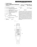
[0008] FIG. 1 is a schematic view of a watch having a microphone in accordance with an exemplary embodiment.
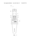
[0009] FIG. 2 is a diagram of the watch of FIG. 1 in accordance with an exemplary embodiment.
DETAILED DESCRIPTION
[0010] Referring to FIG. 1, a watch 10 includes a main body 20 and a sound input body 30. In the embodiment, the watch 10 further includes a strap configured to tie the main body 20 to user's wrist, and the sound input body 30 is mounted on the strap. In an alternative embodiment, the sound input body 30 is mounted on the main body 20. The main body 20 includes a display screen for displaying time and data.
[0011] Referring to FIG. 2, the main body 20 includes a control unit 21, a power transmitting coil unit 22, a signal receiving coil unit 23, and a signal amplification unit 24, an interface unit 25, a power transmitting unit 26, and a power supply 27. The sound input body 30 includes a microphone 31, a power receiving coil unit 32, a signal transmitting coil unit 33, and a power receiving unit 34. The signal transmitting coil unit 33 is connected to the microphone 31. The power transmitting coil unit 22 and the signal receiving coil unit 23 are mounted on the main body 20, where the power transmitting coil unit 22 coupling the power receiving coil unit 32 and the signal receiving coil unit 23 coupling the signal transmitting coil unit 33. In the embodiment, the power transmitting coil unit 22 and the signal receiving coil unit 23 are mounted on a frame of the main body 20.
[0012] The power supply 27 powers the main body 20 when there is no sound signal input. The power supply 27 provides an initial working voltage for enabling the microphone 31 to receive sound signal input by a user. The sound signal input is converted into electric signal by the microphone 31. The signal transmitting coil unit 33 generates an inducted electromagnetic field in response to the electric signal transmitted by the microphone 31. In the embodiment, the microphone 31 is mounted on the surface of the strap.
[0013] The generation of the electromagnetic field results in the generation of electric signal in the signal receiving coil unit 23. The signal amplification unit 24 is connected between the signal receiving coil unit 23 and the interface unit 25, and configured to amplify the electric signal from the signal receiving coil unit 23. The control unit 21 recognizes the electric signal amplified by the signal amplification unit 24 via the interface unit 25 to execute a corresponding function.
[0014] The power transmitting unit 26 is connected between the signal amplification unit 24 and the control unit 21, and configured to convert the electric signal into a voltage signal with a predetermined value.
[0015] The power transmitting coil unit 22 generates an inducted electromagnetic filed in response to the voltage signal converted by the signal amplification unit 24. The generation of the electromagnetic field results in the generation of electric signal in the power receiving coil unit 32. The power receiving unit 34 is connected to the microphone 31, and converts the electric signal from the power receiving coil unit 32 into a voltage signal with a predetermined value for powering the microphone 31. Thereby, the microphone 31 can receive sound signal input by a user powered by the power receiving unit 34.
[0016] It is understood that the present disclosure may be embodied in other forms without departing from the spirit thereof. Thus, the present examples and embodiments are to be considered in all respects as illustrative and not restrictive, and the disclosure is not to be limited to the details given herein.
User Contributions:
Comment about this patent or add new information about this topic:
Images included with this patent application:
 |  |
 |
| Similar patent applications: | |
| Date | Title |
|---|---|
| 2014-09-18 | Adjustable biasing circuits for mems capacitive microphones |
| 2014-09-18 | Slim speaker structure having vibration effect |
| 2009-11-26 | Wind immune microphone |
| 2009-12-03 | Ear hook microphone |
| 2011-01-20 | Waterproof microphone |
| New patent applications in this class: | |
| Date | Title |
|---|---|
| 2019-05-16 | Noise eliminating device, echo cancelling device, and abnormal sound detecting device |
| 2016-07-14 | Method and system of extending battery life of a wireless microphone unit |
| 2016-04-21 | Analogue signal processing circuit for microphone |
| 2016-03-03 | Wireless programmable microphone apparatus and system for integrated surveillance system devices |
| 2016-02-25 | Systems and methods for using a speaker as a microphone |
| New patent applications from these inventors: | |
| Date | Title |
|---|---|
| 2016-06-30 | Battery-free smart key |
| 2016-05-26 | Vehicle electronic key system |
| 2016-02-04 | On-vehicle wireless charging system, wireless charger and car charger thereof |
| Top Inventors for class "Electrical audio signal processing systems and devices" | |
| Rank | Inventor's name |
|---|---|
| 1 | Hiroshi Akino |
| 2 | Yang-Won Jung |
| 3 | Liang Liu |
| 4 | Markus Christoph |
| 5 | Shou-Shan Fan |