Patent application title: LED lamp
Inventors:
Wei-Che Hsieh (Taipei, TW)
IPC8 Class: AH05B3308FI
USPC Class:
315122
Class name: With automatic shunt and/or cutout plural load device systems series connected load devices
Publication date: 2014-06-26
Patent application number: 20140175983
Abstract:
A lamp is provided with a full-wave rectifier for convert AC to DC; a SPD
electrically connected to the full-wave rectifier for protecting the lamp
from voltage spikes; series connected LEDs electrically connected to the
SPD; a microprocessor electrically connected to the SPD; series connected
MOSFET start circuits electrically to the microprocessor, the MOSFET
start circuits configured to switch electronic signals; and resistors
each electrically interconnected the LED and the MOSFET start circuit. In
response to a normal DC supplied from the SPD, the microprocessor creates
a PWM signal to activate the MOSFET start circuits which in turn initiate
operations of the LEDs via the resistors respectively. In response to an
abnormal DC having voltage spikes supplied from the SPD, the
microprocessor deactivates the MOSFET start circuits which in turn direct
the DC through the resistors rather than supply the DC to the LEDs via
the resistors respectively.Claims:
1. A lamp comprising: a full-wave rectifier for convert alternating
current (AC) to direct current (DC); a surge protection device (SPD)
electrically connected to the full-wave rectifier for protecting the lamp
from voltage spikes; a plurality of light-emitting diodes (LEDs)
connected in series and electrically connected to the SPD; a
microprocessor electrically connected to the SPD; a plurality of
metal-oxide-semiconductor field-effect transistor (MOSFET) start circuits
connected in series and electrically to the microprocessor, the MOSFET
start circuits being configured to switch electronic signals; and a
plurality of resistors each electrically interconnected the LED and the
MOSFET start circuit; wherein in response to a normal DC supplied from
the SPD, the microprocessor creates a pulse-width modulation (PWM) signal
to activate the MOSFET start circuits which in turn initiate operations
of the LEDs via the resistors respectively; and wherein in response to an
abnormal DC having voltage spikes supplied from the SPD, the
microprocessor deactivates the MOSFET start circuits which in turn direct
the DC through the resistors rather than supply the DC to the LEDs via
the resistors respectively.Description:
BACKGROUND OF THE INVENTION
[0001] 1. Field of the Invention
[0002] The invention relates to lamps and more particularly to a light-emitting diode (LED) lamp with improved starting characteristic.
[0003] 2. Description of Related Art
[0004] LEDs are renowned for their long life and their ability to resist shock. Also, an LED consumes much less electrical power than fluorescent lamps. Therefore, LED lighting devices are gaining popularity worldwide. Recently, LEDs as a light source have been employed in outdoor lighting devices.
[0005] Starting of a fluorescent lamp can be one of preheating, instant start, rapid start, quick-start, semi-resonant start, and programmed start.
[0006] However, an LED light having the characteristic of preheating of a fluorescent lamp has not been disclosed as far as the present inventor is aware. Thus, continuing improvements in the exploitation of LED light having above characteristic are constantly being sought.
SUMMARY OF THE INVENTION
[0007] It is therefore one object of the invention to provide a lamp comprising a full-wave rectifier for convert alternating current (AC) to direct current (DC); a surge protection device (SPD) electrically connected to the full-wave rectifier for protecting the lamp from voltage spikes; a plurality of light-emitting diodes (LEDs) connected in series and electrically connected to the SPD; a microprocessor electrically connected to the SPD; a plurality of MOSFET (metal-oxide-semiconductor field-effect transistor) start circuits connected in series and electrically to the microprocessor, the MOSFET start circuits being configured to switch electronic signals; and a plurality of resistors each electrically interconnected the LED and the MOSFET start circuit; wherein in response to a normal DC supplied from the SPD, the microprocessor creates a PWM (pulse-width modulation) signal to activate the MOSFET start circuits which in turn initiate operations of the LEDs via the resistors respectively; and wherein in response to an abnormal DC having voltage spikes supplied from the SPD, the microprocessor deactivates the MOSFET start circuits which in turn direct the DC through the resistors rather than supply the DC to the LEDs via the resistors respectively.
[0008] The above and other objects, features and advantages of the invention will become apparent from the following detailed description taken with the accompanying drawings.
BRIEF DESCRIPTION OF THE DRAWINGS
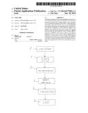
[0009] FIG. 1 is a block diagram of an LED lamp according to the invention;
[0010] FIG. 2 is a circuit diagram of the LED lamp;
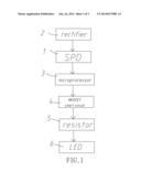
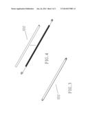
[0011] FIG. 3 is a perspective view of the LED lamp; and
[0012] FIG. 4 is an exploded view of the LED lamp shown in FIG. 3 with the LEDs removed.
DETAILED DESCRIPTION OF THE INVENTION
[0013] Referring to FIGS. 1 to 4, an LED lamp 100 in accordance with the invention is shown. The LED lamp 100 is shaped as a fluorescent lamp. That is, the invention is implemented within a typical fluorescent lamp (e.g., T5, T8, T9, or PL lamp) without modification of the shape and the external components (e.g., pins) of the fluorescent lamp. The LED lamp 100 comprises the following components as discussed in detail below.
[0014] A full-wave rectifier consists of two half-wave rectifiers 2 provided at both ends respectively and is used to convert alternating current (AC) to direct current (DC). A surge protection device (SPD) 1 is electrically connected to one half-wave rectifier 2 for protecting the LED lamp 100 from voltage spikes. A plurality of (two are shown) LEDs 6 connected in series are electrically interconnected the SPD 1 and the other half-wave rectifier 2. A microprocessor 3 is electrically connected to the SPD 1. Two MOSFET (metal-oxide-semiconductor field-effect transistor) start circuits 4 are connected in series and are electrically to the microprocessor 3. Two high resistance members (i.e., resistors) 5 are provided and each high resistance member 5 is electrically interconnected the LED 6 and the MOSFET start circuit 4. Further, the electrical circuit between the SPD 1 and one LED 6 is grounded and the electrical circuit between the other LED 6 and the other half-wave rectifier 2 is also grounded.
[0015] Operations of the invention are described in detail below. In response to a normal DC voltage supplied from the SPD 1, the microprocessor 3, as a preheating of a fluorescent lamp, creates a PWM (pulse-width modulation) signal to activate the MOSFET start circuits 4. The MOSFET start circuits 4 having the function of switching electronic signals initiate operations of the LEDs 6 via the high resistance members 5 respectively.
[0016] To the contrary, in response to an abnormal DC voltage (e.g., voltage spikes) supplied from the SPD 1, the microprocessor 3 deactivates the MOSFET start circuits 4 which in turn direct electric current through the high resistance members 5 rather than supply electric current to the LEDs 6 via the high resistance members 5 respectively. As a result, the LEDs 6 are protected.
[0017] While the invention has been described in terms of preferred embodiments, those skilled in the art will recognize that the invention can be practiced with modifications within the spirit and scope of the appended claims.
User Contributions:
Comment about this patent or add new information about this topic:
Images included with this patent application:
 |  |
 |  |
| New patent applications in this class: | |
| Date | Title |
|---|---|
| 2016-12-29 | Semiconductor light source driving apparatus |
| 2016-12-29 | Spectral shift control for dimmable ac led lighting |
| 2016-07-14 | Illumination system and luminaire |
| 2016-06-23 | Light emitting module |
| 2016-06-23 | Backlight unit and display device including backlight unit |
| New patent applications from these inventors: | |
| Date | Title |
|---|---|
| 2021-12-02 | Euv photo masks and manufacturing method thereof |
| 2021-10-28 | Extreme ultraviolet mask and method of manufacturing the same |
| 2013-01-31 | Light harvesting lens module |
| Top Inventors for class "Electric lamp and discharge devices: systems" | |
| Rank | Inventor's name |
|---|---|
| 1 | John L. Melanson |
| 2 | Anatoly Shteynberg |
| 3 | Robert R. Soler |
| 4 | Fredric S. Maxik |
| 5 | David E. Bartine |