Patent application title: SURGICAL INSTRUMENT
Inventors:
Mark Edwin Housman (North Attleborough, MA, US)
Mark Edwin Housman (North Attleborough, MA, US)
Assignees:
SMITH & NEPHEW, INC.
IPC8 Class: AA61B1704FI
USPC Class:
606232
Class name: Surgery instruments suture retaining means (e.g., buttons)
Publication date: 2014-06-19
Patent application number: 20140172016
Abstract:
The present invention relates to a surgical anchor delivery system (10)
including a delivery device (11) having a shaft (14) and a handle (13),
an advancer (15) for advancing a surgical anchor (12) distally along the
shaft (14); and a plurality of surgical anchors (12) loaded upon the
shaft (14).Claims:
1. A surgical anchor delivery system comprising a delivery device
comprising a shaft and a handle, and an advancer for advancing a surgical
anchor distally along the shaft; and a plurality of surgical anchors
loaded upon the shaft.
2. A delivery system according to claim 1, wherein at least one of the plurality of surgical anchors comprises a lumen which extends through a longitudinal axis of the anchor.
3. A delivery system according to claim 2, wherein one of the plurality of surgical anchors comprises a closed distal end and a lumen which extends through a part of the longitudinal axis of the anchor.
4. A delivery system according to claim 1, wherein a distal region of the delivery device shaft comprises a non-circular cross section.
5. A delivery system according to claim 1, wherein the delivery device shaft comprises a lumen.
6. A delivery system according to claim 1, wherein the delivery device shaft comprises one or more longitudinal slots or grooves in its outer surface.
7. A delivery system according to claim 1, wherein the delivery device shaft comprises a pointed distal tip.
8. A delivery system according to claim 1, wherein the advancer comprises a tubular member or sleeve slidably mounted on the delivery device shaft, proximally of the most proximal surgical anchor, and further comprises means for advancing the tubular member or sleeve distally.
9. A delivery system according to claim 8, wherein the means for advancing comprises a knob mounted rotationally on the shaft.
10. A delivery system according to claim 9, wherein the tubular member or sleeve comprises a threaded proximal region and the knob comprises means for engaging the threaded proximal region.
11. A delivery system according to claim 8, wherein the tubular member or sleeve is coupled to a pin or tab.
12. A delivery system according to claim 11, wherein the pin or tab is coupled with an indexer which enables predefined distal advancement of the tubular member or sleeve relative to the shaft.
13. A delivery system according to claim 1, wherein the advancer comprises a ratchet mechanism for distally advancing the tubular member or sleeve.
14. A delivery system according to claim 1, wherein the advancer comprises a rod which is moveable within a longitudinal channel formed within the delivery device shaft.
15. A delivery system according to claim 14, wherein the rod comprises a radially extending pin which projects from the longitudinal channel.
16. A delivery system according to claim 1, wherein the handle comprises one or more suture cleats.
17. A delivery system according to claim 1, wherein the plurality of surgical anchors comprises of 2, 3, 4, 5 or more anchors.
18. A delivery system according to claim 17, wherein the surgical anchors are loaded with suture; preferably two or more sets of suture.
19. A delivery system according to claim 17, wherein the surgical anchors are connected to each other by an adjustable suture which comprises slip-knot.
Description:
[0001] The present invention relates to surgical instrument, and more
particularly to surgical instrument for delivering surgical anchors.
[0002] Surgical anchors are typically supplied with a single-use disposable delivery device, with each anchor delivery system including a delivery device pre-loaded with a single anchor. Frequently, a surgical procedure will involve the use of two or more surgical anchors, necessitating the use of several delivery devices. However, from a procedural perspective this is both inefficient and expensive since for most anchor delivery systems, the bulk of the costs are attributable to the cost of the disposable delivery device, and not the anchor itself. Therefore, a more cost effective and procedurally efficient approach is desirable.
[0003] In its broadest sense the present invention provides a surgical anchor delivery system including a delivery device having an elongate shaft coupled with a handle, and means for advancing a surgical anchor distally along the shaft; and a plurality of surgical anchors loaded upon the shaft of the delivery device.
[0004] According to an aspect of the present invention there is provided a surgical anchor delivery system including a delivery device having an elongate shaft coupled with a handle, and an advancer for advancing a surgical anchor distally along the shaft; and a plurality of surgical anchors loaded upon the shaft.
[0005] Suitably, the plurality of surgical anchors consists of two, three, four, five or more anchors, which are loaded in series upon the elongate shaft.
[0006] The surgical anchors may be fenestrated or non-fenestrated.
[0007] Preferably, the surgical anchors are loaded with suture. Suitably, each surgical anchor is loaded with two or more sets of suture.
[0008] Optionally, the surgical anchors are connected to each other by suture. The suture may be adjustable and include a slip-knot.
[0009] Preferably, at least one of the plurality of surgical anchors includes a lumen which extends through a longitudinal axis of the anchor. This arrangement allows the anchor to be slidably mounted on the delivery device shaft, which passes through the anchor lumen so that the entire anchor is mounted on the shaft. Suitably, all of the plurality of surgical anchors include a lumen which extend through a longitudinal axis of each anchor. Alternatively, one of the plurality of surgical anchors includes a closed distal end and a lumen which partially extends through the anchor along its longitudinal axis. Suitably, the closed distal end is tapered; preferably, to a point. In this alternative embodiment, the remaining anchors of the plurality of surgical anchors all include a lumen which extends through a longitudinal axis of the anchor. Those anchors are slidably mounted upon the delivery device shaft, and the anchor having the closed distal end is mounted on the distal tip of the delivery device shaft.
[0010] Preferably, at least a distal region of the delivery device shaft has a non-circular cross section. Suitably, at least a distal region of the shaft has a hexagonal cross-section. Alternatively, the shaft has a generally circular cross-section and includes one or more cut-out regions formed by longitudinal grooves in the shaft surface. Suitably, the longitudinal grooves are formed in the distal region of the shaft and extend proximally along at least part of the length of the shaft. This prevents anchors possessing a lumen and loaded on the delivery device from rotating relative to the shaft. As a result, the delivery device can be used to rotationally advance the anchors into tissue.
[0011] Optionally, the delivery device shaft includes a lumen. The lumen may be axial or offset from the longitudinal axis of the shaft. Alternatively or additionally, the delivery device shaft includes one or more longitudinal slots in its outer surface. For example, the shaft may include one, two, three, four or more of such slots. In embodiments featuring a lumen and slots, the slot or slots are connected with the lumen. The purpose of the above features is to permit channelling of suture, which may be attached to one or more of the surgical anchors, through at least a portion of the device, and to exit in the handle region. Such features help to prevent snagging of the suture in the surgical site. In alternative embodiments, described in greater detail below, the advancer is a tubular member or sleeve, slidably mounted upon the shaft, and the suture can be threaded between the advancer sleeve and the shaft. According to this alternative embodiment, the shaft and or sleeve may contain a channel or groove respectively in their outer or inner surfaces to accommodate the suture and to prevent snagging between the shaft and sleeve.
[0012] Suitably, the delivery device shaft includes a pointed distal tip. Suitably, the pointed distal tip is sharpened or blunted. Suitably, the distal tip includes a threaded region. The tip can be used to prepare a small pilot hole prior to rotatably driving or pounding the anchor directly into bone.
[0013] Suitably, the advancer is a tubular member or sleeve mounted on the delivery device shaft. Suitably, the advancer is mounted proximally of, and its distal end abuts against, the most-proximal surgical anchor loaded on the device shaft. Suitably, the advancer includes means for advancing the tubular member or sleeve distally. Suitably, the advancer includes a knob mounted rotationally on the shaft. Suitably, the tubular member or sleeve includes a threaded proximal region and the knob includes means for engaging the threaded proximal region. Alternatively, the tubular member or sleeve is coupled to an adaptor at its proximal end or at a proximal region, and the adaptor includes threaded portion which is engageable with the threaded proximal region of the knob. Such arrangement provides that when the knob is rotated in a first direction, the tubular member or sleeve advances distally relative to the shaft. Optionally, the knob may rotate in a second direction, opposite to the first direction, to retract the tubular member or sleeve proximally relative to the shaft.
[0014] Alternatively, the tubular member or sleeve is coupled to a pin or tab. The pin or tab may be coupled with an indexer which enables predefined distal advancement of the tubular member or sleeve. For example, the delivery device shaft may include one or more detents or apertures for receipt of the pin or tab which is coupled with, and moveable relative to, the sleeve. The pin or tab can be moved to engage and disengage with the detents or apertures. The advancer may also include a handle or knob for controlling movement of the sleeve relative to the shaft; or the knob can be formed with the pin and tab to engage/disengage the pin or tab with the detents or apertures and also advance the sleeve relative to the shaft. Further alternatively, the tubular member or sleeve includes a series of apertures in its wall, which extend at least partially along its length, and the delivery device shaft includes one or more sprung pins for engagement with one or more of the apertures. For example, each of the one or more sprung pins is biased radially outwards and engages with an aperture of the sleeve. In order to advance the sleeve, the biased pin is compressed to disengage it from the aperture, the sleeve is moved distally, and the compressive force on the pin is removed once the sleeve has been advanced to a position where the pin can engage another aperture in the sleeve wall. The advancer can also include a ratchet mechanism for distally advancing the tubular member or sleeve.
[0015] In use, the tubular member or sleeve abuts against the proximal end of the most proximal of the plurality of surgical anchors. When the distal-most anchor has been deployed, the tubular member or sleeve is moved distally to advance the remaining anchor or anchors loaded on the delivery device shaft to a position where the most-distal anchor is at the distal end of the delivery device shaft and ready for deployment. This process can be repeated until all the anchors have been deployed.
[0016] Further alternatively, the advancer is a rod which is moveable within a longitudinal channel formed within the delivery device shaft. Suitably, the rod includes a radially extending pin which projects from the longitudinal channel. Suitably, the pin abuts against the proximal end of the most proximal of the plurality of surgical anchors, and is used to advance distally any surgical anchors which remain on the delivery device shaft after the distal most surgical anchor has been deployed. Suitably, the advancer includes a knob mounted rotationally on the shaft. Suitably, the rod includes a threaded proximal region and the knob includes means for engaging the threaded proximal region. Such arrangement provides that when the knob is rotated in a first direction, the rod advances distally relative to the shaft. The rod can be moved to advance the surgical anchors by any other suitable mechanisms, including those described above in relation to the sleeve.
[0017] Preferably, the handle includes one or more suture cleats.
[0018] The above and other aspects of the invention will now be described with reference to the following drawings in which:
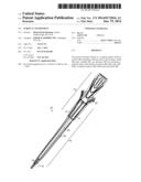
[0019] FIG. 1 is a side view of a surgical anchor delivery system according to a first embodiment of the invention;
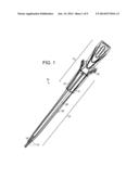
[0020] FIG. 2 is a close-up partial side view of the distal region of the embodiment of FIG. 1;
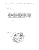
[0021] FIG. 3 is a sectional view along the line A-A of FIG. 2;
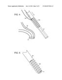
[0022] FIG. 4 is a close-up partial perspective view of the distal region of the embodiment of FIG. 1 in which a first surgical anchor has been deployed;
[0023] FIG. 5 is a close-up partial perspective view of the embodiment of FIG. 4 in which a second anchor has been advanced distally;
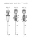
[0024] FIGS. 6A-C are side and sectional side views of the embodiment of FIG. 1 before and after deployment of a first surgical anchor;
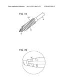
[0025] FIGS. 7A&B are close-up partial views of the distal tip of a delivery system shaft according to a second embodiment of the invention;
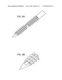
[0026] FIGS. 8A&B are close-up partial views of the distal tip of a delivery system shaft according to a third embodiment of the invention;
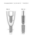
[0027] FIG. 9 is a close-up partial view of the distal region of a delivery system according to a fourth embodiment of the invention;
[0028] FIG. 10 is a close-up partial view of the distal region of a delivery system according to a fifth embodiment of the invention;
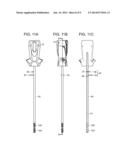
[0029] FIGS. 11A-C are side and sectional views of a delivery system according to a sixth embodiment of the invention; and
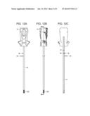
[0030] FIGS. 12A-C are side and sectional views of a delivery system of FIG. 10 in which a first surgical anchor has been deployed and a second surgical anchor has been advanced distally.
[0031] Referring to FIG. 1 there is shown surgical anchor delivery system 10 formed of a delivery device 11 and two more surgical anchors in the form of suture anchors 12. The delivery device 11 includes a proximal handle 13 having a shaft 14 extending therefrom, two suture anchors 12 mounted in series at the distal end of shaft 14, and a mechanism 15 for advancing the anchors distally.
[0032] Mechanism 15 is formed from a sleeve 20 and driver 21. Sleeve 20 is slidably mounted on shaft 14 and has a distal end which abuts against the proximal-most surgical anchor. Driver 21 is formed with handle 13 and is rotationally mounted upon shaft 14, and in use can be actuated to advance sleeve 20 distally to move the proximal-most anchor into a position suitable for deployment, once the distal-most anchor has been deployed. This process will be described in greater detail below, with reference to FIGS. 4 to 6.
[0033] In FIG. 1, and the further Figures illustrating the invention, a gap is depicted between successive anchors. This is entirely for illustrative purposes to indicate the presence of multiple anchors. In practice, the anchors abut against each other, as shown in the close-up view of FIG. 2, which prevents the distal-most anchor from sliding back proximally during its deployment.
[0034] The illustrated embodiments are generally depicted as including two surgical anchors. However, the system can be preloaded with three, four, five or more surgical anchors.
[0035] In FIG. 2 the distal end of the delivery device is shown in greater detail. Here, two suture anchors 12a, 12b are slidably mounted and arranged in series upon shaft 14. In the embodiments illustrated in FIGS. 1 to 8, the anchors have a helical-shaped body 22 which includes apertures 23 between turns 24 of the helical body. The apertures 23 permit tissue in-growth by allowing cell- and nutrient-bearing fluids to flow through the anchor. The anchor further includes two support struts 25 (FIG. 3) about which the helical body 22 is disposed. The support struts 45 provide structural rigidity and integrity to the anchor which allow it to be rotational deployment of the anchors.
[0036] As can be seen in FIG. 3 (view along the line A-A of FIG. 2), the shaft 14 has a non-circular cross-section. This prevents rotation of the anchor during deployment. In the embodiment shown, the shaft has a generally circular cross-section and includes opposed cut-out regions caused by longitudinal grooves in its outer surface along at least part of its length, which accommodate support struts 25 of the anchors. In alternative embodiments, not shown, the shaft has a polygonal cross section. For example, at least the distal region of the shaft has a triangular, square or hexagonal cross-section. As mentioned above, the non-circular cross-section of the shaft is important for preventing rotation of the anchors during their deployment. The entire shaft may have a non-circular cross-section, although it will be recognised that only the distal region of the shaft, on which the anchors lie, requires a non-circular cross-section to achieve the intended purpose.
[0037] Each suture anchor 12 is double loaded with suture 30, which runs from the distal end of the assembly to the handle at the proximal end of the system. The handle further includes suture cleats 32 for securing the free suture ends. In alternative embodiments, not shown, the suture anchor is loaded with a single suture, three, four or more sutures. The suture can be exposed, as shown, or can be threaded through at least a portion of the delivery system, through a lumen or slot in the shaft, or between the shaft and sleeve, for example.
[0038] Referring now to FIGS. 4 to 6, in use, the distal-most anchor 12a of the delivery system is rotationally driven directly into bone or into a pre-drilled pilot hole or bone tunnel 31, using the delivery device. As shown in FIG. 4, the first anchor 12a has been deployed into bone (anchor 12a is hidden from view). The delivery device is then removed (FIG. 4), and sleeve 20 advanced distally by rotating driver 21. During this process the sleeve 20 abuts against the proximal end of anchor 12b and, as it moves distally, pushes anchor 12b to the end of shaft 14 ready for its subsequent deployment (FIG. 5).
[0039] FIGS. 6B and 6C provide sectional side views of the delivery system along the line B-B of FIG. 6A before and after deployment of the distal most-anchor 12a, and subsequent advancement distally of the proximal-most anchor 12b to a position ready for its deployment.
[0040] Shaft 14 is secured within the proximal region of handle 13. As shown, driver 21 includes an inner hub 18 and an outer hub 19, both of which are mounted coaxially with shaft 14. A proximal portion 20' of sleeve 20 is coupled to the outer hub 19 via inner hub 18. The inner hub 18 includes a distal portion 18a, a proximal portion 18b, and a cannulation 18c. The inner hub proximal portion 18b includes threads 18b' on its outer surface. The inner hub 18 is located in a cavity 19a of the outer hub 19. The cavity 19a includes a distal portion 19a' and a proximal portion 19a''. The proximal portion 19a'' includes threads 19b that engage the threads 18b' on the proximal portion outer surface of inner hub 18. Due to the threaded engagement between threads 18b' and threads 19b, rotation of driver 21, and thus outer hub 19, causes the sleeve 20 to move axially along the length of the shaft 14. Rotation of the outer hub 19 is discontinued when the distal-most anchor, post-deployment of the previously distal-most anchor, is positioned on the distal end of the shaft ready for deployment, or when an end 18a' of the inner hub distal portion 18a engages an end 19c of the cavity distal portion 19a'. This last condition is met when the proximal-most anchor has been advanced and is positioned on the distal end of the shaft ready for deployment.
[0041] Referring now to FIGS. 7A and 7B, there is shown a shaft 14 having a modified tapered distal tip 14' which includes a helical thread 14'' having the same thread pattern as the illustrated anchor 12b'. This feature is intended to aid insertion of the anchor directly into bone without the need for a pre-drilled pilot hole, or with minimal hole preparation.
[0042] FIGS. 8a and 8B show an alternative shaft tip design in which the tip is pointed. The pointed tip may be sharp or blunt.
[0043] In FIG. 9 there is shown the distal region of a delivery system having alternative non-fenestrated helically threaded anchors 33, in which no apertures are present between turns 24'.
[0044] The distal region of a further alternative delivery system is illustrated in FIG. 10. According to this embodiment, the anchors are of the pound-in type in which the anchors are advanced into bone by hammering or pounding the proximal end of the handle of the delivery device, rather than being rotationally driven into bone, as with the previously described embodiments. Anchors according to these embodiments include radial fins, wings or ribs.
[0045] Referring now to FIGS. 11 and 12, there is shown a delivery device having an alternative advancer mechanism. The delivery device includes a proximal handle 13' having a shaft 41 extending therefrom, two suture anchors 12a', 12b' mounted in series at the distal end of shaft 41, and a mechanism for advancing the anchors distally.
[0046] According to this embodiment, and as shown along sections C-C and D-D, shaft 41 is secured within the proximal region of handle 13'. The delivery device includes a sleeve 40 slidably mounted on shaft 41, and coupled at a proximal portion 40' to the shaft 41 by engagement of connecting pin 36 with shaft aperture 37. Prior to deployment of the distal-most suture anchor 12a', the sleeve 40 is fixed in a first position with respect to the shaft 41 by engagement of connecting pin 36 with shaft aperture 37, as depicted in FIGS. 11A-11C. Upon insertion of the distal-most suture anchor 12a' into the repair site, connecting pin 36 is temporally disengaged from shaft aperture 37, and the shaft 41, and sleeve 40 is indexed axially by pushing knob 35, which is mounted on sleeve 40, such that anchor 12b' is moved to the distal end of shaft 41. Once anchor 12b' has been correctly positioned at the distal end of the shaft, the position of sleeve 40 is fixed relative to shaft 41 by the engagement of connecting pin 36 with a second shaft aperture 38, as shown in FIGS. 12A-12C.
[0047] The described delivery system is preferably a sterile, single use delivery device having multiple suture anchors loaded on a single drive shaft. The delivery system is intended for surgical anchors which allow a driver to pass directly through them. The distal-most anchor can be replaced by an anchor which includes a partial cannulation and a solid tip. In the illustrated embodiments, the sutures are attached to the proximal end of each anchor. In alternative embodiments, not shown, the suture is attached to the anchor in its proximal region, or anywhere between the distal and proximal ends of the anchor. The proximal anchors may be advanced to the tip of the shaft of the delivery device using the described rotational mechanism or by means of the described indexer which can be advanced distally and locked once the distal-most anchor has been deployed and the next most-distal anchor has been advanced to the end of the delivery device shaft. The pusher mechanism can include a ratchet mechanism, and/or suitable rod and slot mechanism with appropriate engaging pins.
[0048] The components of the anchor assembly, and the handle and hubs of the delivery device, can be formed from a polymer material and by an injection moulding process. However, other materials and processes may be used. The handle and hubs are coupled via an interference fit, although other processes of coupling may be used. The components of the shaft can be made from a metal material via an extrusion or drawings process, and are coupled to the handle and hubs via a threaded fit or an interference fit. Other suitable materials, and methods of coupling may also be used
[0049] Rather than a sleeve bearing on the proximal end of the anchor, the anchor can be advanced down the shaft by other indexing mechanisms.
[0050] In configurations other than proximal suture attachment, suture slots are added to the exterior of the anchor to accommodate the suture.
[0051] This invention allows for multiple anchors to be deployed from a single delivery device, without the need for reloading, which would be extremely difficult in the surgical theatre given the small nature of these kinds of devices. This potentially reduces procedural time as the number of sterile implants opened and introduced to the surgical field is reduced. In addition, the system reduces the amount of waste generated per procedure by reducing the quantity of disposable instrumentation and packaging thereby supporting green initiatives and sustainably concerns.
User Contributions:
Comment about this patent or add new information about this topic:
| People who visited this patent also read: | |
| Patent application number | Title |
|---|---|
| 20180003336 | FITTING STRUCTURE FOR SUPPLY OF GAS |
| 20180003334 | THERMAL ENCLOSURE |
| 20180003333 | PIPE COUPLING FOR CONNECTING TWO PIPE ENDS OR PIPE CLAMP FOR SEALING A DEFECTIVE PIPE |
| 20180003332 | CURED IN PLACE PIPE SYSTEM HAVING INTEGRATED THERMOPLASTIC WITH IMPROVED MELT-FLOW CHARACTERISTICS |
| 20180003331 | TUBULAR LINER FOR REHABILITATING UNDERGROUND AND SURFACE PIPES AND PIPELINES |
Images included with this patent application:
 |  |
 |  |
 |  |
 |  |
 |  |
| Similar patent applications: | |
| Date | Title |
|---|---|
| 2014-06-26 | Surgical instrument |
| 2014-07-10 | Surgical instrument |
| 2014-07-31 | Powered surgical instrument |
| 2014-07-31 | Electrosurgical gripping instrument |
| 2014-07-31 | Surgical spacer instrument and method |
| New patent applications in this class: | |
| Date | Title |
|---|---|
| 2019-05-16 | Suture anchor apparatus |
| 2019-05-16 | Suture anchors and method of use |
| 2019-05-16 | Methods for reattaching detached tissue to hard tissue using bioinductive patch |
| 2018-01-25 | Wrapping clip for securing a flexible line to another ojbect |
| 2018-01-25 | Knotless suture anchor with unthreaded nose |
| New patent applications from these inventors: | |
| Date | Title |
|---|---|
| 2017-01-26 | Anchor having a controlled driver orientation |
| 2016-12-29 | Threaded suture anchor |
| 2016-05-05 | Miniaturized dual drive open architecture suture anchor |
| 2016-02-11 | Blended shaft drive |
| 2015-11-19 | Composite interference screws and drivers |
| Top Inventors for class "Surgery" | |
| Rank | Inventor's name |
|---|---|
| 1 | Lutz Biedermann |
| 2 | Roger P. Jackson |
| 3 | Wilfried Matthis |
| 4 | Frederick E. Shelton, Iv |
| 5 | Joseph D. Brannan |