Patent application title: ABLATION PROBE WITH TISSUE SENSING CONFIGURATION
Inventors:
James E. Dunning (Lafayette, CO, US)
James E. Dunning (Lafayette, CO, US)
Eric W. Larson (Commerce City, CO, US)
Jennifer Mchenry (Denver, CO, US)
Assignees:
Covidien LP
IPC8 Class: AA61B1818FI
USPC Class:
606 33
Class name: Instruments electrical application electromagnetic wave irradiation
Publication date: 2014-06-19
Patent application number: 20140171932
Abstract:
An ablation probe is provided. The ablation probe includes a housing that
is configured to couple to a microwave energy source. A shaft extends
distally from the housing and includes a radiating section at a distal
end thereof. A sensor assembly is operably disposed on the housing and
includes a pair of sensor contacts. One or more sensors are positioned
adjacent the radiating section and extend along the shaft. The sensor(s)
have a pair of sensor contact pads that are positioned on the shaft for
contact with the pair of sensors such that during transmission of
microwave from the radiating section into target tissue at least one
electrical parameter is induced into the at least one sensor and detected
by the pair of sensor contacts.Claims:
1. An ablation probe, comprising: a housing configured to couple to a
microwave energy source; a shaft extending distally from the housing, the
shaft including a radiating section at a distal end thereof; a sensor
assembly operably disposed within the housing and including a pair of
sensor contacts; and at least one sensor positioned adjacent the
radiating section and extending along the shaft, the at least one sensor
having a pair of sensor contact pads positioned on the shaft for contact
with the pair of sensors such that during transmission of microwave
energy from the radiating section into target tissue at least one
electrical parameter is induced into the at least one sensor and detected
by the pair of sensor contacts.
2. An ablation probe according to claim 1, wherein the at least one sensor including the pair of sensor contact pads is formed from a silver ink deposition that is provided on an exterior surface of the shaft.
3. An ablation probe according to claim 2, wherein the silver ink deposition is provided on the exterior surface of the shaft via a process selected from the group consisting of pad printing, laser ablation and direct write.
4. An ablation probe according to claim 2, wherein the silver ink deposition includes at least two depositions that are spaced-apart from one another forming at least two conductive traces that culminate at the sensor contact pads.
5. An ablation probe according to claim 1, wherein the at least one electrical parameter is selected from the group consisting of impedance and capacitance, and wherein the at least one electrical parameter is induced via an interrogatory pulse generated from a circuit of the microwave energy source.
6. An ablation probe according to claim 1, wherein the sensor assembly includes a sensor housing that is configured to support the pair of sensor contacts.
7. An ablation probe according to claim 6, wherein the sensor contacts of the pair of sensor contacts are positioned apart from one another within the sensor housing to contact the sensor contact pads and include a proximal end and distal end, wherein the distal end is disposed in oblique relation with respect to the proximal end.
8. An ablation probe according to claim 6, wherein each sensor contact of the pair of sensor contacts is resilient and configured to flex when the shaft is inserted through an aperture in the sensor housing for coupling to the housing.
9. An ablation probe according to claim 1, wherein the proximal end of each sensor contact of the pair of sensor contacts is configured to couple to a corresponding lead that extends within the housing and couples to the microwave energy source for communication with one or more modules associated therewith.
10. An ablation probe according to claim 9, wherein the proximal end of each sensor contact of the pair of sensor contacts is configured to couple to corresponding clocking features that are provided on an end cap and hub that are positioned within the housing, the clocking features configured to facilitate aligning and coupling the sensor housing to the housing of the ablation probe.
11. An ablation probe according to claim 1, wherein the radiating section transmits microwave energy at a frequency that ranges from about 2300 MHz to about 2450 MHz.
12. An ablation probe according to claim 1, wherein a polyester heat shrink wrap is provided along the shaft and covers the at least one sensor.
13. An ablation probe according to claim 1, wherein a ceramic trocar tip is provided at distal tip of the shaft and is configured to pierce tissue.
14. An ablation probe according to claim 1, further including in-flow and out-flow tubes that are provided on the housing of the ablation probe and configured to cool the radiating section of the shaft.
15. A method for manufacturing a microwave ablation probe comprising: forming a housing configured to couple to a microwave energy source; forming a shaft having a radiation section and at least one sensor including a pair of sensor contacts; forming a sensor assembly including a sensor housing that couples to the pair of sensor contacts; and coupling the shaft to the housing such that each sensor of the pair of sensors contacts a corresponding one of the sensor contacts such that during transmission of microwave energy from the radiating section into target tissue at least one electrical parameter may be induced into the at least one sensor and detected by the pair of sensor contacts.
16. A method according to claim 15, including forming the at least one sensor including the pair of sensor contact pads via a silver ink deposition that is provided on an exterior surface of the shaft.
17. A method according to claim 16, including utilizing a process selected from the group consisting of pad printing, laser ablation and direct write to provide the silver ink deposition on the exterior surface of the shaft.
18. A method according to claim 16, wherein forming the at least one sensor including the pair of sensor contact pads via a silver ink deposition further includes forming at least two depositions that are spaced-apart from one another forming at least two conductive traces that culminate at the sensor contact pads.
19. A method according to claim 15, including utilizing an overmolding process to couple the sensor housing to the pair of sensor contacts.
20. A method according to claim 19, further including bending each sensor contact of the pair of sensor contacts such that distal ends of each sensor contact of the pair of sensor contacts are angled toward one another and are positioned apart from one another within the sensor housing to contact the sensor contact pads.
Description:
CROSS REFERENCE TO RELATED APPLICATION
[0001] The present application claims the benefit of and priority to U.S. Provisional Application Ser. No. 61/738,021, filed on Dec. 17, 2012, the entire contents of which are incorporated herein by reference.
BACKGROUND
[0002] 1. Technical Field
[0003] The present disclosure relates to an ablation probe. More particularly, the present disclosure relates to an ablation probe with one or more tissue sensing configurations.
[0004] 2. Description of Related Art
[0005] Utilizing microwave thermal therapy to treat target tissue is known in the art. Specifically, one or more suitable microwave antennas that are coupled to an energy source may be positioned adjacent target tissue. Subsequently, electrosurgical energy, e.g., microwave energy, may be transmitted to a radiating section of the microwave antenna and is directed to target tissue, which, in turn, results in thermal coagulation. Typically, a surgeon relies on one or more imaging devices, systems and/or techniques to facilitate in the microwave thermal therapy. For example, such imaging devices, systems and/or techniques may be utilized to determine placement of the microwave antenna relative to target tissue, ablation completion of target tissue and/or ablation zone size of treated target tissue.
[0006] While the aforementioned imaging devices, systems and/or techniques may work well in a number of applications, (e.g., determining, for example, placement of the microwave antenna relative to target tissue) such imaging devices, systems and/or techniques, typically, do not provide automatic shut off when the microwave antenna is purposefully and/or inadvertently withdrawn from or not fully inserted into target tissue. In either of the foregoing scenarios, unintentional thermal injury to a patient and/or clinician is possible.
SUMMARY
[0007] As can be appreciated, an ablation probe with one or more tissue sensing configurations may prove useful in the surgical arena. Specifically, one or more tissue sensing configurations that are configured to detect ablation probe placement within tissue can prove advantageous for increasing performance and/or patient safety.
[0008] Embodiments of the present disclosure are described in detail with reference to the drawing figures wherein like reference numerals identify similar or identical elements. As used herein, the term "distal" refers to the portion of a surgical instrument that is being described which is further from a user, while the term "proximal" refers to the portion of the surgical instrument that is being described which is closer to a user.
[0009] An aspect of the present disclosure provides an ablation probe. The ablation probe includes a housing that is configured to couple to a microwave energy source. A shaft extends distally from the housing and includes a radiating section at a distal end thereof. A sensor assembly is operably disposed within the housing and includes a pair of sensor contacts. One or more sensors are positioned adjacent the radiating section and extend along the shaft. The sensor(s) have a pair of sensor contact pads that are positioned on the shaft for contact with the pair of sensors. During transmission of microwave energy from the radiating section into target tissue one or more electrical parameters are induced into the sensor(s) and detected by the pair of sensor contacts. The electrical parameter(s) may be impedance and/or capacitance. The electrical parameter(s) may be induced via an interrogatory pulse generated from a circuit of the microwave energy source.
[0010] The sensor(s) and the pair of sensor contact pads may be formed from a silver ink deposition that is provided on an exterior surface of the shaft. The silver ink deposition may be provided on the exterior surface of the shaft via pad printing, laser ablation and/or direct write. The silver ink deposition may include two or more depositions that are spaced-apart from one another forming two or more conductive traces that culminate at the sensor contact pads.
[0011] Moreover, the sensor assembly may include a sensor housing that is configured to support the pair of sensor contacts. The sensor contacts of the pair of sensor contacts may be positioned apart from one another within the sensor housing to contact the sensor contact pads and may include a proximal end and distal end. The distal ends may be disposed in oblique relation with respect to the proximal ends. Each sensor contact of the pair of sensor contacts may be resilient and configured to flex when the shaft is inserted through an aperture in the sensor housing for coupling to the housing. Each sensor contact of the pair of sensor contacts may be configured to couple to a corresponding lead that extends within the housing and couples to the microwave energy source for communication with one or more modules associated therewith. The proximal ends of the sensors may be configured to couple to corresponding clocking features that are provided on an end cap and hub that are positioned within the housing. The clocking features may be configured to facilitate aligning and coupling the sensor housing to the housing of the ablation probe.
[0012] The radiating section may be configured to transmit microwave energy at a frequency that ranges from about 2300 MHz to about 2450 MHz. Moreover, a polyester heat shrink wrap may be provided along the shaft and covers the sensor(s). Additionally, a ceramic trocar tip may be provided at distal tip of the shaft and may be configured to pierce tissue. Further, in-flow and out-flow tubes may be provided on the housing of the ablation probe and configured to cool the radiating section of the shaft.
[0013] An aspect of the present disclosure provides a method for manufacturing a microwave ablation probe. A housing configured to couple to a microwave energy source is formed. A shaft having a radiation section and one or more sensors including a pair of sensor contacts is formed. A sensor assembly including a sensor housing that couples to a pair of sensor contacts is formed. The shaft is coupled to the housing such that each sensor of the pair of sensors contacts a corresponding one of the sensor contacts such that during transmission of microwave energy from the radiating section into target tissue one or more electrical parameters may be induced into the sensor(s) and detected by the pair of sensor contacts.
[0014] The method may include forming the sensor(s) including the pair of sensor contact pads via a silver ink deposition that is provided on an exterior surface of the shaft. The method may include utilizing a process such as, for example, pad printing, laser ablation and direct write to provide the silver ink deposition on the exterior surface of the shaft.
[0015] Forming the sensor(s) including the pair of sensor contact pads via a silver ink deposition may include forming two or more depositions that are spaced-apart from one another forming at least two conductive traces that culminate at the sensor contact pads.
[0016] The method may include utilizing an overmolding process to couple the sensor housing to the pair of sensor contacts. The method may also include bending each sensor contact of the pair of sensor contacts such that the sensor contacts are angled toward one another and are positioned apart from one another within the sensor housing to contact the sensor contact pads.
BRIEF DESCRIPTION OF THE DRAWING
[0017] Various embodiments of the present disclosure are described hereinbelow with references to the drawings, wherein:
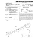
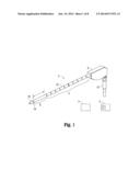
[0018] FIG. 1 is a right, perspective view of an ablation probe having a sensing configuration according to an embodiment of the present disclosure;
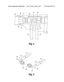
[0019] FIG. 2 is a partial, left side view of the ablation probe depicted in FIG. 1 with a left side portion of a housing being removed to illustrate a portion of a sensor assembly according to an embodiment of the present disclosure;
[0020] FIG. 3 is a left, perspective view illustrating a pair of sensor contacts of the sensor assembly depicted in FIG. 2;
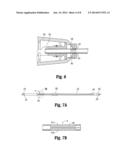
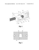
[0021] FIG. 4 is a left, perspective view illustrating the sensor assembly coupled to an end cap of the ablation probe;
[0022] FIG. 5 is a cut-away view taken along line segment 5-5 in FIG. 4 with a shaft of the ablation probe removed;
[0023] FIG. 6 is a partial, top elevated view of the ablation probe depicted in FIG. 1 with a top portion of a housing being removed and a top portion of a sensor housing removed to illustrate the sensor contacts in contact with sensor pads disposed on the shaft of the ablation probe;
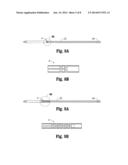
[0024] FIG. 7A is a side view of the shaft including a sensor configuration according to an embodiment of the instant disclosure;
[0025] FIG. 7B is an enlarged area of detail depicted in FIG. 7A;
[0026] FIG. 8A is a side view of the shaft including a sensor configuration according to another embodiment of the instant disclosure;
[0027] FIG. 8B is an enlarged area of detail depicted in FIG. 8A;
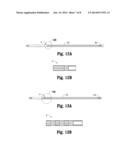
[0028] FIG. 9A is a side view of the shaft including a sensor configuration according to yet another embodiment of the instant disclosure;
[0029] FIG. 9B is an enlarged area of detail depicted in FIG. 9A;
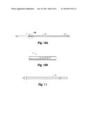
[0030] FIG. 10A is a side view of the shaft including a sensor configuration according to still another embodiment of the instant disclosure;
[0031] FIG. 10B is an enlarged area of detail depicted in FIG. 10A;
[0032] FIG. 11 is a side view of the shaft including a sensor configuration according to still yet another embodiment of the instant disclosure;
[0033] FIG. 12A is a side view of the shaft including a sensor configuration according to still yet another embodiment of the instant disclosure;
[0034] FIG. 12B is an enlarged area of detail depicted in FIG. 12A;
[0035] FIG. 13A is a side view of the shaft including a sensor configuration according to still yet another embodiment of the instant disclosure;
[0036] FIG. 13B is an enlarged area of detail depicted in FIG. 13A;
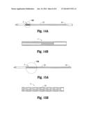
[0037] FIG. 14A is a side view of the shaft including a sensor configuration according to still yet another embodiment of the instant disclosure;
[0038] FIG. 14B is an enlarged area of detail depicted in FIG. 14A;
[0039] FIG. 15A is a side view of the shaft including a sensor configuration according to still yet another embodiment of the instant disclosure; and
[0040] FIG. 15B is an enlarged area of detail depicted in FIG. 15A.
DETAILED DESCRIPTION
[0041] Detailed embodiments of the present disclosure are disclosed herein; however, the disclosed embodiments are merely examples of the disclosure, which may be embodied in various forms. Therefore, specific structural and functional details disclosed herein are not to be interpreted as limiting, but merely as a basis for the claims and as a representative basis for teaching one skilled in the art to variously employ the present disclosure in virtually any appropriately detailed structure.
[0042] In accordance with the instant disclosure, one or more sensor configurations are provided on an ablation probe to detect one or more properties that may be associated with target tissue and/or a specific surgical procedure. Specifically, the sensor configuration(s) provides feedback to a clinician or directly to a source of electrosurgical energy, e.g., a microwave generator, to improve overall performance of the ablation device and/or safety to a patient or clinician. To this end, the sensor configuration(s) includes one or more conductive traces that are deposited on an exterior surface of a shaft of the ablation probe and interrogated at a predetermined frequency to measure one or more electrical properties, e.g., capacitance and/or impedance, that are induced in the conductive traces.
[0043] Turning now to FIG. 1, an ablation probe 2 including a sensor configuration 4 according to an embodiment of the present disclosure is illustrated. In accordance with the instant disclosure, sensor configuration 4 may also be utilized to serve as centimeter depth markings. Ablation probe 2 is configured to electrosurgically treat tissue utilizing electrosurgical energy having a frequency that ranges from about 2300 MHz to about 2450 MHz. In embodiments, ablation probe 2 may be configured to electrosurgically treat tissue utilizing electrosurgical energy having a frequency that is less than 2300 MHz (e.g., 915 MHz) and greater than 2450 MHz. It has been shown through empirical testing that utilizing microwave energy from about 2300 MHz to about 2450 MHz has clear advantages when compared to more traditional frequency platforms, e.g., 915 MHz. Specifically, and in accordance with the instant disclosure, ablation probe 2 utilizes microwave energy that is provided by a microwave energy source, e.g., a generator 3 (FIG. 1), and transmitted at a frequency that ranges from about 2300 MHz to about 2450 MHz to create ablation zones that have a more spherical configuration for a specified range of activation times when compared to conventional ablation probes. Moreover, this higher frequency range allows ablation probe 2 to utilize a radiating section 6 (FIG. 1) that includes a length that is relatively short when compared to radiating sections of conventional ablation probes. As can be appreciated, radiating section 6 provides enhanced focus of the microwave energy transmitted therefrom and into target tissue, which, in turn, allows the microwave energy to penetrate deeper and faster into target tissue, which, in turn, results in a desired tissue effect with shorter activation times of radiating section 6.
[0044] Continuing with reference to FIG. 1, ablation probe 2 includes a housing 8 that is formed from one or more suitable materials, e.g., plastic, metal, metal alloy, ceramic, etc. Housing 8 functions as a handle that may be grasped by a user and is configured to house one or more components of ablation probe 2. A proximal end of housing 8 operably couples to a hub 10 (FIG. 1) that couples a cable 12 to ablation probe 2 and one or more leads 14, 16 (FIG. 2) that are disposed within housing 8. Proximal end 8 also couples to in-flow and out-flow tubes 18, 20 (FIG. 2), respectively, that are coupled to a coolant source 5 (FIG. 1) configured to provide one or more suitable coolants, e.g., saline, to a shaft 22 that serves as a cooling jacket and surrounds radiating section 6.
[0045] Shaft 22 may be formed from any suitable material, e.g., metal, glass fiber, and extends distally from housing 8. In the illustrated embodiment, shaft 22 is formed from glass fiber Shaft 22 includes a distal end 24 (FIGS. 1 and 7A) that includes a ceramic tip 25 (FIGS. 1 and 7A) configured to pierce tissue for positioning radiating section 6 adjacent target tissue. Shaft 22 also includes a proximal end 26 that operably couples to one or more components disposed within housing 8. Specifically, proximal end 26 includes a pair of indents 28 (FIG. 7A) that are configured to couple to a pair of corresponding detents (not explicitly shown) that are provided within a hub 30 (FIGS. 2, 4 and 6).
[0046] Hub 30 defines in-flow ports 32 and out-flow ports 34 that are configured to couple to corresponding in-flow tubes 18 and out-flow tubes 20 (FIG. 2). In-flow and out-flow ports 32, 34, respectively, communicate with one or more lumens (not explicitly shown) that extend through housing 8 and into shaft 22 forming a closed-loop path for providing coolant to radiating section 6. Hub 30 includes one or more clocking features (not explicitly shown) that align with one or more corresponding clocking features (not explicitly shown) disposed on an end cap 36 (FIG. 4) that operably couples to a distal end of hub 30. The clocking features on hub 30 and end cap 36 are configured to provide passage for leads 14, 16 so that leads 14, 16 may be coupled to a pair of sensor contacts 38, 40 (FIGS. 2-4 and 6) of a sensor assembly 42 (FIG. 2).
[0047] Continuing with reference to FIG. 2, sensor assembly 42 is operably disposed within housing 8 and includes sensor contacts 38, 40 that are configured to contact a corresponding pair of sensor contact pads 44 (see FIGS. 6-7A for example) positioned on shaft 22. Specifically, during transmission of microwave energy from radiating section 6 into target tissue, one or more electrical parameters, e.g., capacitance and/or impedance, is induced into one or more conductive traces 46 (FIGS. 7A-7B) and detected by sensor contacts 38, 40. Alternatively, a separate interrogation circuit 7 (FIG. 1) may be configured to apply a separate voltage to conductive traces 46 and measure current associated therewith to determine capacitance and/or impedance. In this embodiment, interrogation circuit 7 may be in communication with one or more modules (not shown) of generator 3 and configured to calculate capacitance and/or impedance. The interrogation frequency utilized may range from about 50 KHz to about 4 MHz.
[0048] Referring to FIGS. 3-4, sensor contacts 38, 40 are spaced apart a predetermined distance from one another within a sensor housing 48 that is configured to support sensor contacts 38, 40 (as best seen in FIG. 4). Proximal ends 50, 52 of sensor contacts 38, 40, respectively, are configured to couple to corresponding leads 14, 16 that extend within housing 8 (FIG. 3). Leads 14, 16 couple to the microwave energy source to provide communication between sensor contacts 38, 40 and one or more modules (not explicitly shown) of the microwave energy source.
[0049] In the illustrated embodiment, distal ends 54, 56 are offset from proximal ends 50, 52 (as best seen in FIG. 3) to facilitate contact between sensor contacts 38, 40 and sensor contact pads 44. Specifically, distal ends 54, 56 are disposed in oblique relationship with respect to respective proximal ends 50, 52 and are in substantial horizontal alignment with one another.
[0050] Referring to FIG. 5, a predetermined gap is provided between the distal ends 54, 56 and may be determined during the manufacture process. More particularly, the distance of the gap between distal ends 54, 56 is smaller than an outside diameter of shaft 22; this will facilitate contact between distal ends 54, 56 and sensor contact pads 44. Specifically, each of distal ends 54, 56 includes a sensor contact surface 58, 60 (FIGS. 3 and 5) that is configured slide across a corresponding sensor contact pad 44 when shaft 22 is positioned through an aperture 62 that provides passage through sensor housing 48 (see FIGS. 4-5). In embodiments, sensor contact surfaces 58, 60 may be biased outwardly from distal ends 54, 56 and movable therein. Specifically, as shaft 22 is positioned within aperture 62 the larger diameter of shaft 22 causes sensor contact surfaces 58, 60 to translate into distal ends 54, 56. As can be appreciated, this reduces the likelihood of sensor contact surfaces 58, 60 inadvertently scrapping/or scratching off the silver ink depositions that form sensor contact pads 44 as shaft 22 is inserted through aperture 62. Additionally, distal ends 54, 56 are flexible and configured to flex when shaft 22 is positioned through aperture 62. Specifically, notched out portions 64 (one of notched portions 64 is shown in FIG. 4) are provided on sensor housing 48 and allow distal ends 54, 56 to flex or give as shaft 22 is positioned within aperture 62. The flexibility of distal ends 54, 56 may be adjusted or varied during the manufacturing process as needed.
[0051] With reference now to FIGS. 7A-7B, an embodiment of sensor configuration 4 (sensor 4) is illustrated. In the embodiment illustrated in FIGS. 7A-7B, sensor 4 is positioned adjacent radiating section 6 and extends a predetermined length along shaft 22. In accordance with the instant disclosure, sensor 4 is defined by one or more conductive traces 46 that are formed from a silver ink deposition provided on the exterior surface of shaft 22. A silver ink deposition was utilized because of its ability to withstand EtO (Ethylene Oxide) sterilization. Other types of ink depositions including but not limited to gold, copper and nickel may also be utilized. One or more methods or processes may be utilized for depositing the silver ink onto the exterior of surface of shaft 22. For example, pad printing, laser ablation and direct write are suitable methods for depositing the silver ink onto the exterior surface of shaft 22.
[0052] In the illustrated embodiments, the silver ink deposition is utilized to form two or more conductive traces 47a, 47b (FIG. 7B) that are spaced apart a predetermined distance from one another. For example, in embodiments, the distance that conductive traces 47a, 47b are spaced apart from one another may range from about 0.010 inches to about 0.080 inches. As can be appreciated, the distance that separates conductive traces 47a, 47b may be varied or altered during the silver ink deposition process. Accordingly, in embodiments, the distance that separates conductive traces 47a, 47b may be less than 0.050 mm or greater than 0.080 mm.
[0053] Continuing with reference to FIG. 7A each of conductive traces 47a, 47 extends from distal end 24 adjacent radiating section 6 to proximal end 26 adjacent detents 28 and culminates at sensor contact pads 44 that are also formed during the aforementioned silver ink deposition process. The distance that separates conductive traces 47a, 47 and sensor contact pads 44 ranges from about 0.050 inches to about 0.100 inches. As can be appreciated, the distance that separates conductive traces 47a, 47b and sensor contact pads 44 may be varied or altered during the silver ink deposition process. Accordingly, in embodiments, the distance that separates conductive traces 47a, 47b and sensor contact pads 44 may be less than 0.001 mm or less than 0.300 mm. The important part of this feature are to have the contact pads spaced far enough apart to ensure electrical isolation from one another, but large enough pad area to ensure contact with the pogo-pin.
[0054] FIGS. 8A-15B illustrate various other configurations of sensor 4. Each of the configurations of sensor 4 shown in FIGS. 8A-15B may be formed utilizing the aforementioned materials and silver ink deposition processes. Sensors 4 illustrated in FIGS. 7A-15B may include any suitable configuration, such as, for example, two horizontal bars (FIGS. 8A-8B), two vertical bars (FIGS. 7A-7B), multi-band horizontal bars (FIGS. 9A-9B), spiral bars (FIGS. 10A-10B), or other suitable configuration (see FIGS. 11-15B for example). The specific configuration of sensor 4 utilized with ablation probe 2 will depend on a manufactures preference, a type of surgical procedure, target tissue (e.g., liver, ling, kidney, etc.), signal to noise ration parameters, etc.
[0055] A shrink wrap 66 (shown in phantom in FIG. 7A), e.g., polyester heat shrink wrap, is provided along shaft 22 to encapsulate conductive traces 47a, 47b and sensor contact pads 44. Shrink wrap 66 is utilized to maintain the structural integrity of conductive traces 47a, 47b and/or sensor contact pads 44. Moreover, shrink wrap 66 is utilized to protect a patient from silver bio-incompatibility. Further, it serves as a nonstick coating to prevent ablated tissue from sticking to sensor 4, e.g., conductive traces 47a, 47b.
[0056] In accordance with the instant disclosure, ablation probe 2 is configured to function in two modes of operation. Specifically, in a first mode of operation, e.g., a standard or manual ablation mode, sensor 4 may be configured to detect when ablation probe 2 or component associated therewith, e.g., radiating section 6, has been properly inserted, e.g., fully positioned, within target tissue and may be configured to automatically terminate power to ablation probe 2 if radiating section 6 is inadvertently or purposefully removed from target tissue. In this particular mode of operation, a clinician may position radiating section 6 of ablation probe 2 within target tissue. One or more modules associated with generator 3 may be coupled to conductive traces 47a, 47b and configured to send an interrogatory pulse thereto to determine if radiating section 6 has been properly inserted into target tissue, e.g., liver tissue. If the module(s) detects a predetermined capacitance and/or impedance induced within conductive traces 47a, 47b, a clinician may initiate the transmission of microwave energy to radiating section 6. It has been shown through empirical testing that suitable interrogation frequencies for capacitance may range from about 200 KHz to about 600 KHz. Moreover, it has been shown through empirical testing that suitable interrogation frequencies for impedance may range from about 40 KHz to about 600 KHz. In manual mode of operation, generator 3 automatically shuts off if radiating section 6 is inadvertently or purposefully removed from target tissue during transmission of microwave energy therefrom.
[0057] Moreover, in a second mode of operation, e.g., a resection mode, the generator may be configured to automatically initiate and terminate power to ablation probe 2 based on proper insertion of ablation probe 2. In this particular mode of operation, a clinician may position radiating 6 of section ablation probe 2 within target tissue. One or more modules associated with generator 3 may be coupled to conductive traces 47a, 47b and configured to send an interrogatory pulse thereto to determine if radiating section 6 has been properly inserted into target tissue, e.g., liver tissue. In resection mode, if the module(s) detects a predetermined capacitance and/or impedance induced within conductive traces 47a, 47b, generator 3 automatically initiates the transmission of microwave energy to radiating section 6. Generator 3 automatically shuts off if radiating section 6 is inadvertently or purposefully removed from target tissue during transmission of microwave energy therefrom. This particular mode of operation allows a clinician to rapidly change positions down a resection line without having to manually turn the generator on and off.
[0058] From the foregoing and with reference to the various figure drawings, those skilled in the art will appreciate that certain modifications can also be made to the present disclosure without departing from the scope of the same. For example, while the aforementioned disclosure has been described in terms of use of utilizing sensor 4 in conjunction for determining proper insertion of radiating section 6 into tissue, sensor 4 may be utilized to determine other parameters that may associated with ablation probe 2 and/or a surgical procedure. For example, sensor 4 may be configured to detect tissue type, progression of a microwave ablation procedure, completion of a microwave ablation procedure, etc. Moreover, in embodiments, sensor 4 may be utilized to detect the presence of a cooling fluid that is being circulated through ablation probe 2 and/or component associated therewith, e.g., shaft 22; this could mitigate circulation errors, e.g., a clinician forgets to circulate fluid to radiating section 6. As can be appreciated, this may increase the operative shelf life of radiating section 6 and/or ablation probe 2.
[0059] While several embodiments of the disclosure have been shown in the drawings, it is not intended that the disclosure be limited thereto, as it is intended that the disclosure be as broad in scope as the art will allow and that the specification be read likewise. Therefore, the above description should not be construed as limiting, but merely as exemplifications of particular embodiments. Those skilled in the art will envision other modifications within the scope and spirit of the claims appended hereto.
User Contributions:
Comment about this patent or add new information about this topic:
Images included with this patent application:
 |  |
 |  |
 |  |
 |  |
 |
| Similar patent applications: | |
| Date | Title |
|---|---|
| 2013-03-28 | Method and system for in situ tissue expansion |
| 2009-12-03 | Tissue lesion evaluation |
| 2011-06-23 | Tissue engineered constructs |
| 2011-06-30 | Apparatus and method for body tissue fixation |
| 2014-05-01 | Cardiac tissue elasticity sensing |
| New patent applications in this class: | |
| Date | Title |
|---|---|
| 2017-08-17 | Microwave ablation antenna assemblies |
| 2017-08-17 | Systems and methods for determining the status of a fluid-cooled microwave ablation system |
| 2016-12-29 | Electrosurgical apparatus for generating radiofrequency energy and microwave energy for delivery into biological tissue |
| 2016-12-29 | Ablation device with sensor |
| 2016-09-01 | Microwave antenna assembly and method of using the same |
| New patent applications from these inventors: | |
| Date | Title |
|---|---|
| 2021-06-17 | System and method of manufacturing non-stick coated electrodes |
| 2016-05-12 | System for tracking and imaging a treatment probe |
| 2016-02-18 | Microwave antenna probes and methods of manufacturing microwave antenna probes |
| 2016-02-11 | Energy-delivery system and method for controlling blood loss from wounds |
| 2016-02-11 | Microwave ablation catheter and method of utilizing the same |
| Top Inventors for class "Surgery" | |
| Rank | Inventor's name |
|---|---|
| 1 | Lutz Biedermann |
| 2 | Roger P. Jackson |
| 3 | Wilfried Matthis |
| 4 | Frederick E. Shelton, Iv |
| 5 | Joseph D. Brannan |