Patent application title: EQUIPMENT SLING
Inventors:
David Malara (Loveland, CO, US)
IPC8 Class: AA45F314FI
USPC Class:
224264
Class name: Carried by animate bearer flaccid attaching means looped around neck or crossing shoulder strap cushion or positioner located at shoulder
Publication date: 2014-06-12
Patent application number: 20140158726
Abstract:
An equipment sling is disclosed. An example equipment sling includes an
outer casing having at least one channel formed therein. An inner cord is
provided through the channel. A grip material may be provided on the
outer casing to substantially maintain a position of the outer casing on
a user's shoulder. A liner may be provided in the outer casing to reduce
friction between the inner cord and the outer casing. An attachment
member on each end of the inner cord can attach the inner cord to an
equipment item. The inner cord is configured to travel through the at
least one channel formed in the outer casing, while the outer casing
remains in a substantially constant position on a user's shoulder,
thereby enabling the equipment item to be readily raised for use and
lowered for stowage.Claims:
1. An equipment sling comprising: an outer casing having at least one
channel formed therein; an inner cord provided through the channel; and
an attachment member on each end of the inner cord to attach the inner
cord to an equipment item.
2. The equipment sling of claim 1, wherein the outer casing has a grip material to substantially maintain a position of the outer casing on a user's shoulder.
3. The equipment sling of claim 1, wherein the outer casing has at least one liner.
4. The equipment sling of claim 3, wherein the liner is a friction-type material in at least a portion of the channel to add, control, reduce or eliminate friction between the inner cord and the outer casing.
5. The equipment sling of claim 1, wherein the inner cord travels through the at least one channel formed in the outer casing, while the outer casing remains in a substantially constant position on a user's body, thereby enabling the equipment item to be readily raised for use and lowered for stowage.
6. The equipment sling of claim 1, further comprising another attachment member to attach to an article worn by the user to maintain the equipment item in a substantially fixed position even when the user moves.
7. The equipment sling of claim 1, wherein the article worn by the user is at least one of clothing, a belt, a belt loop, and a backpack.
8. The equipment sling of claim 1, further comprising a lock mechanism to adjust a length of the inner cord.
9. An equipment sling comprising: a casing having a lumen formed therethrough; an inner cord provided through the lumen of the casing; and at least one attachment member of the inner cord, the at least one attachment member configured to attach to an equipment item.
10. The equipment sling of claim 9, wherein the casing has a grip material to substantially maintain a position of the casing on a user's shoulder.
11. The equipment sling of claim 9, further comprising a liner in the casing.
12. The equipment sling of claim 9, further comprising a friction-type material to add, control, reduce or eliminate friction between the inner cord and the outer casing.
13. The equipment sling of claim 9, wherein the inner cord travels through the lumen formed in the casing
14. The equipment sling of claim 9, wherein the casing remains in a substantially constant position on a user's body regardless of the user's movement.
15. The equipment sling of claim 9, wherein the equipment item is readily raised for use and lowered for stowage.
16. The equipment sling of claim 9, further comprising another attachment member to attach to an article worn by the user to maintain the equipment item in a substantially fixed position even when the user moves.
17. The equipment sling of claim 9, wherein the article worn by the user is at least one of clothing, a belt, a belt loop, and a backpack.
18. The equipment sling of claim 9, further comprising a lock mechanism to adjust a length of the inner cord.
19. The equipment sling of claim 9, further comprising a plurality of lumen formed through the casing, each lumen housing separate inner cords, each of the separate inner cords for attachment to separate equipment items.
20. An equipment sling comprising: an outer casing having at least one channel formed therein; a size-adjustable inner cord provided through the channel; a grip material on the outer casing to substantially maintain a position of the outer casing on a user's shoulder; a liner in the outer casing to reduce friction between the inner cord and the outer casing; and an attachment member on each end of the inner cord to attach the inner cord to an equipment item; wherein the inner cord travels through the at least one channel formed in the outer casing, while the outer casing remains in a substantially constant position on a user's shoulder, thereby enabling the equipment item to be readily raised for use and lowered for stowage.
Description:
PRIORITY CLAIM
[0001] This application claims the benefit of U.S. Provisional Patent Application No. 61/735,430 filed on Dec. 10, 2012, titled "Sliding Harness" of David Malara, incorporated herein by reference for all that is disclosed as though fully set forth herein.
BACKGROUND
[0002] Cords used to hold equipment (e.g., binoculars) for a user when not in use have many limitations that may include but are not limited to, being difficult to carry when not in use, and to adjust when ready for use. For example, it can be difficult for the user to get the binoculars or other equipment into the correct position for use. In addition, when hanging around the user's neck, the binoculars or other equipment may bump against the user's chest while walking, shift, or otherwise get in the way. The binoculars or other equipment may become tangled and/or even damaged.
BRIEF DESCRIPTION OF THE DRAWINGS
[0003] FIGS. 1A-H are various view of an example equipment sling.
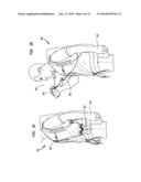
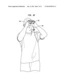
[0004] FIGS. 2A-E illustrate an example equipment sling as a user may operate the equipment sling to raise and lower binoculars (or other equipment).
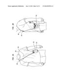
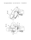
[0005] FIG. 3A and FIG. 3B are front views of a user wearing the equipment sling along with other gear (e.g., a backpack having a waist strap 207).
[0006] FIG. 3C and FIG. 3D are side views corresponding to the front views shown in FIG. 3A and FIG. 3B.
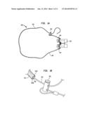
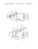
[0007] FIG. 4A and FIG. 4B are illustrations showing the equipment sling as it may be attached or otherwise secured to other article such as a backpack, belt or even a jacket or other item.
[0008] FIG. 5 is an illustration of how an example sliding sling with an attached equipment item may be worn in conjunction with, for example a backpack, or other equipment items.
DETAILED DESCRIPTION
[0009] Binoculars, range finders, portable GPS devices, cameras, and other equipment is often carried and used by hunters, hikers, birders, military personnel, tourists, and others. In many cases, the equipment may have an attached cord to hang around the user's wrist or neck. This cord enables the user to reach the binoculars, or other equipment, while walking without having to stop and unpack the binoculars from a backpack or other pouch.
[0010] An equipment sling is disclosed herein, which may be used to carry equipment on the user's person when not in use, yet be readily accessible to the user when needed.
[0011] In an example, the equipment sling may include an outer casing (e.g., a webbing or other structural material) having at least one channel formed therethrough, an inner cord provided through the channel in the outer casing, and attachment means (e.g., loops, clasps, buckles, or clips) on at least one end, and in an example on each end, of the inner cord for attachment to equipment or other item.
[0012] During use, a user may loop the equipment sling across the user's back and over one shoulder, so that the equipment connected to the cord rests approximately at the user's hip opposite the one shoulder. For example, if the equipment sling is hung on the user's right shoulder, the equipment rests under the user's left arm at about the user's left hip; and vice versa. Of course, the equipment sling may be used on other parts of the user's body, such as across the user's back. When the equipment is needed, for example when the user wants to look through the binoculars, the user can readily reach the binoculars and lift the binoculars toward his or her head. The outer casing remains in a substantially fixed arrangement across the user's shoulder, while the inner cord travels therethrough in a first direction as the binoculars are lifted toward the user's head. When the user is done using the binoculars, he or she can lower the binoculars again toward a resting position near the user's hip. Again, the outer casing remains in a substantially fixed arrangement across the user's shoulder, while the inner cord travels therethrough in a second (opposite) direction so that the binoculars are returned to the resting position.
[0013] Before continuing, it is noted that as used herein, the terms "includes" and "including" mean, but is not limited to, "includes" or "including" and "includes at least" or "including at least." The term "based on" means "based on" and "based at least in part on."
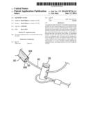
[0014] FIG. 1A shows an example equipment sling 100 illustrating as it may be attached to equipment 202. Although the equipment 202 is shown as binoculars, the equipment sling is not limited to use with binoculars and may be used with any equipment.
[0015] The equipment sling 100 described herein may be used to carry binoculars, range finders, cameras, and/or like products, but can be adapted to transport other items that one would want to carry in a similar fashion. The sling provides a means to carry binoculars and/or other items comfortably and securely, while still providing easy access to the item, e.g., when wearing a backpack.
[0016] The sling may have one or more of the following features: two piece design, sliding ability, ease of use, strong and durable, versatile (e.g. for use with different equipment and different users), readily used with backpack, wheelchair, or other devices, fits all binoculars and other equipment, maintains the binoculars or other equipment secure and reduces or altogether prevents bouncing during use, maintains the binoculars in a position out of the way of the user, quick and easy size adjustment, enables the user to carry two or more items at a time (such as cameras, one on each hip), comfortable to wear, enables one hand operation, is easy to put on and take off, and can be comfortably worn during a wide variety of activities.
[0017] In the example shown in FIG. 1A, a casing 101 is shown having an inner cord 103. The inner cord 103 is provided slidably through a channel or lumen formed in the casing 101. The inner cord 103 may be connected on either end to the equipment 202.
[0018] In an example, the casing 101 may be comprised of two strips of equal or different lengths that are sewn (or otherwise provided) together on the outer edges to form a channel or lumen therein. In another example, a single piece of material may be folded and seamed by binding the edges together, thereby forming the channel or lumen through at least a part of the interior.
[0019] The casing 101 may be made of any suitable material, such as but not limited to, a webbing material. The casing 101 may also be referred to herein as an "outer casing," as the inner cord 103 travels through a channel or lumen formed in the casing 101.
[0020] Multiple seams may be sewn into the outer casing material to create multiple channels. These channels may be formed beside or atop one another. A spacer may be provided to create a larger channel and therefor allow for a wider inner cord or multiple cords in one channel.
[0021] A liner material (e.g., a frictionless material such as nylon) may also be incorporated as part of the channel to reduce friction and/or noise created by the inner cord 103 during use. Other friction-controlling materials may also be used, e.g., to add, control, reduce, or eliminate friction. For example, a material may be used to add friction, thereby reducing "swing" during walking or running. Other materials may be used that enable controlling the amount of friction (e.g., by adding and/or reducing friction based on user preferences). A grip fabric (or other material type, such as fleece, neoprene, wool, cotton) may be provided on the outer side of the casing 101 to help the casing 101 remain in place (e.g., across the user's shoulder and/or back and/or chest during use. Other materials may also be provided, e.g., to add visual appeal, camouflage, padding, and/or sound absorption. For example, a shoulder pad may be provided.
[0022] In an example, the ends of the casing 101 may be left at least partially open for the inner cord to pass into the channel. FIG. 1B is a close-up view showing the cord 103 extending through an opening formed in one end of the outer casing 101. In this example, two sides 101A and 101B of the outer casing 101 form a channel or lumen 102 therein. That is, the casing 101 may be comprised of two strips 101A and 101B of equal or different lengths that are sewn together on the outer edges so that there is a channel 102 formed in the center. In another example, the casing 101 may be formed from one strip that is folded in half and sewn together lengthwise along the edges.
[0023] In an example, the method of manufacture described above forms an opening at the ends of the casing 101. In another example, the ends of the casing 101 may be fully sewn together (or otherwise closed), and an opening provided on one side of both ends of the casing 101, (e.g., by a grommet, button hole, or any opening or slit), thereby allowing for the inner cord 103 to pass through the opening. Multiple openings may also be provided, e.g., as illustrated in FIG. 1H. These openings (e.g., opening 109 shown in FIG. 1H) may allow for size adjustment (e.g., the length of cord 103 extending from outer casing 101 based on the opening 109 the cord 103 is exiting from); and/or multiple inner cords may exit at different openings 109 (e.g., from multiple channels in the casing 101) for attachment of more than one equipment item.
[0024] The cord 103 may be provided as a cord material (e.g., a 3/16 inch 550 para cord), strap, rope, or fabric piece, natural or man-made, elastic or non-elastic, that fits in the channel and may easily slide through the channel. The cord may be referred to herein as an "inner cord" 103, as it runs through the lumen or channel formed in the outer casing 101.
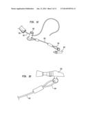
[0025] Loops 104 may be provided on one or both ends of the inner cord 103. Loops 104 may include an attachment means which allows the inner cord to be attached to the binoculars 202 or other equipment. FIG. 1C and FIG. 1D are close-up views showing an example of one of the loops 104 of the equipment sling 100 as it may be attached to an equipment item such as the binoculars 202. The loop 104 is formed on a portion of the inner cord 103 that extends out from the outer casing 101, and serves to attach the binoculars 202 to cord 103.
[0026] In an example, the cord 103 may be size adjustable to enable the binoculars 202 to hang at various heights (e.g., for different height and/or desires of the user). By way of illustration, the cord 103 may be adjusted using a "cord lock" such as the buckle 105 shown in FIG. 1C. The cord lock (or other mechanical or non-mechanical device; more generally referred to as a "locking mechanism"), may be attached to the inner cord 103. The cord lock may be operated to adjust the size of the sling, e.g., to accommodate different body sizes. The cord lock may also be used to reposition the sling into a correct body position when the binoculars 202 or equipment item or are raised/lowered.
[0027] By way of further illustration, FIG. 1E shows an example reducing loop 106. The reducing loop 106 is attached to a strap portion 108, which is in turn attached to the equipment unit 202. The inner cord 103 is threaded through the reducing loop 106. The cord can be pulled in a first direction through a wider part of the reducing loop, and then positioned and pulled back through the thinner portion of the reducing loop to "lock" in place. As such, the cord 103 may be made to any desired size.
[0028] Other examples for adjusting the size of the cord 103 are also contemplated, such as but not limited to a barrel-lock. An example cord lock 105 or "barrel lock" is shown (FIG. 1B) attached to the inner cord 103. In an example, the barrel lock enables the inner cord 103 to be lengthened and/or shortened.
[0029] It is noted that the cord lock may be any mechanical or non-mechanical device. In addition, more than one cord lock may be provided, and one or more of the cord locks may also serve to aid in returning the binoculars back to the user's hip area. For example, spring-loaded cord reels may be used, with or without built-in locking mechanisms.
[0030] In the example shown, equipment sling 100 includes at least one attachment member (e.g., quick-release clips such as carabineers). A first attachment member may be attached to one of the loops 104, near an equipment attachment point. A second attachment member may be attached to another one of the loops 104. In another example, one of the attachment members (or a third attachment member) may be provided to fasten the equipment sling 100 and/or binoculars 202 to an article such as but not limited to, a backpack, belt loop, or other article having a position that is fixed or relatively fixed on the user. It is also noted that further loops 104 and/or attachment points may also be added to accommodate other equipment or accessories.
[0031] It is noted that the equipment sling 100 shown in the drawings is only illustrative. Still other embodiments are also contemplated as being within the scope of the disclosure herein. As a non-limiting example, any of a variety of different types and/or configurations of attachments may be used to attach the equipment sling 100 to the binoculars 202 (or other equipment).
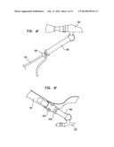
[0032] By way of further illustration, FIG. 1F shows a buckle attachment for the sliding sling. One side of the buckle, clip, or other attachment device (referred to herein as clip 107A) is attached in this example to the outer casing 101 and the other side of the clip 107B is attached to a strap 108 on the equipment 202. In an example, clip 107A and 107B maintains the inner cord from sliding through the outer casing. For example, this allows the user to lock the equipment 202, not allowing them to move through the cord, thus securing the equipment 202 in one place on the user's body.
[0033] FIG. 1G shows an example sliding sling with a buckle attachment means and a reducing loop attachment means for attachment of the sling to an equipment unit. The buckle 107 attaches the equipment unit 202 on one side to the outer casing 101. The sling's inner cord 103 is attached to the other side of the equipment unit 202 by a reducing loop 106, the reducing loop is attached to a strap 108, which attaches to the equipment unit 202.
[0034] Still other example attachment means include, but are not limited to slit keys, cable ties, clips, or buckles, being side release buckles or center release buckles, cam buckles, and/or cord locks that may be known as a barrel lock.
[0035] FIGS. 2A-E illustrate an example equipment sling as a user may operate the equipment sling to raise and lower binoculars (or other equipment). FIG. 2A is an illustration of the equipment sling 100 positioned on a user, wherein a pair of binoculars 202 are hanging around a user's torso 206. The equipment sling 100 enables the binoculars 202 to securely rest at the user's hip area 203. FIG. 2B is a side view showing the example equipment sling 100 with the binoculars 202 securely resting at or near the user left hip, e.g., during transport.
[0036] In FIGS. 2C-D, the user is shown raising the binoculars 202 upward. The outer casing of the equipment sling 100 remains substantially fixed on the user's shoulder. As the user raises the binoculars 202, the inner cord travels through the outer casing. The binoculars are shown fully raised to the user's head in FIG. 2E to an in-use position 204.
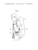
[0037] FIG. 3A and FIG. 3B are front views of a user wearing the equipment sling 100 along with other gear (e.g., a backpack having a waist strap 207). As shown in FIG. 3A, the sling fits over one shoulder and across the user's torso 206, in a resting position near the user's hips 203. In FIG. 3B, the user is shown raising the binoculars 202 to eye level. The equipment sling 100 allows the binoculars 202 to slide easily up toward the user's face, without interfering with the other equipment the user is carrying.
[0038] FIG. 3C and FIG. 3D are side views corresponding to the front views shown in FIG. 3A and FIG. 3B. In FIG. 3C, the equipment sling 100 is shown around the user's 200 neck and over one shoulder, so that the binoculars 202 rest on or near the user's hip area 203. In FIG. 3D, the user 200 is shown raising the binoculars 202 to an in-use position 204. The equipment sling 100 allows this action comfortably and easily. As illustrated in FIG. 3D, when the user 200 takes the binoculars 202 and lifts them for use, e.g., to eye level position 204, this motion can readily be accomplished using only one hand (e.g., without having to disconnect or unpack the binoculars 202). After using the binoculars 202, as the user 200 lowers his or her arm, the inner cord slides inside the outer casing, thus returning the binoculars 202 to their original position in the area of the user's hip 203.
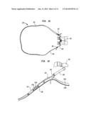
[0039] FIG. 4A and FIG. 4B are illustrations showing the equipment sling 100 as it may be attached or otherwise secured to other article such as a backpack, belt or even a jacket or other item. The user is shown in FIG. 4A attaching the equipment sling 100 and/or the binoculars 202 (e.g., with a clip or other attachment means) to a backpack 205.
[0040] As shown in FIG. 4B, this attachment helps maintain the binoculars 202 tethered in place near the user's hips, even when moving positions such as to a bent over or horizontal position. That is, the attachment maintains the binoculars 202 at the user's hips, and the inner cord 103 moves through the outer casing 101 as the user bends, twists, or otherwise moves (e.g., even walking, running, climbing, and/or crawling).
[0041] The attachment may be made using clip(s), hook(s), or buckle(s), snap hook, spring snap, carabineer, and/or other means for securing the binoculars 202 or other equipment to in a relatively fixed position. For example, one clip (e.g. clamp, hook, or other device to secure the binoculars) is for attachment to the article (e.g. to clothing, back pack, belt loop, etc.). The other clip stays on the binoculars, to be used if no pack is being worn, thus clipping on to the user's clothing, belt loop, etc. The clips function to maintain the binoculars securely near the user's hip area (or other desired position) no matter the activity.
[0042] FIG. 5 is an illustration of how an example sliding sling with an attached equipment item 202 may be worn in conjunction with, for example a backpack 205, or other article. A benefit of the sling 100 described herein is realized when the user is wearing a backpack 205. Because the inner cord slides though the outer casing, there is no friction against the user's body 201 or the backpack 205. With this product, the user is able to wear a backpack 205 and still have easy access to the binoculars 202 or other equipment attached thereto.
[0043] An optional grip fabric, not shown, (or other material type, such as fleece, neoprene, wool, cotton, etc.) may be attached, by sewing means or other attachments means such as with an adhesive, onto the exterior of the outer casing to help maintain the sling in place. As illustrated above, a cord lock, such as a barrel lock (or similar mechanism), may be attached to the inner cord to adjust the size of the sling to accommodate different body sizes. The cord or barrel lock may also be used to reposition the sling into correct body position when the binoculars are raised.
[0044] It is noted that the examples shown and described are provided for purposes of illustration and are not intended to be limiting. Still other examples are also contemplated.
User Contributions:
Comment about this patent or add new information about this topic:
Images included with this patent application:
 |  |
 |  |
 |  |
 |  |
 |  |
 |  |
| Similar patent applications: | |
| Date | Title |
|---|---|
| 2014-10-02 | Receiver mounted sporting equipment rack with longitudinal load bars... |
| New patent applications in this class: | |
| Date | Title |
|---|---|
| 2016-05-12 | Padded strap |
| 2016-02-25 | Strap incorporating a fluid-filled bladder |
| 2015-12-31 | Shoulder strap retention device and method |
| 2015-03-26 | Articulable shoulder strap |
| 2014-07-17 | Device for handles |
| Top Inventors for class "Package and article carriers" | |
| Rank | Inventor's name |
|---|---|
| 1 | Chris Sautter |
| 2 | Zac Elder |
| 3 | Peter Douglas Hubbard |
| 4 | Douglas Harland Murdoch |
| 5 | Jeffrey M. Aftanas |