Patent application title: Seating Furniture
Inventors:
Francesc Serra Codina (Barcelona, ES)
IPC8 Class: AA47C300FI
USPC Class:
2974112
Class name: Chairs and seats armrest
Publication date: 2014-06-05
Patent application number: 20140152069
Abstract:
The seating furniture (1) configures a bench including two side frame
members (2a, 2b), each having two legs (3) connected to a seat-supporting
cross member (4) from which a backrest-supporting post (6) upwardly
extend. Seat slats (16) are connected to the cross members (4) and
backrest slats connected to the posts (6). The seat slats (16) are
secured to first planar profiles (17) forming a seat assembly (5) which
is secured to the cross members (4) by first mounting screws inserted in
through holes of the cross member (4), and the backrest slats are secured
at their ends to second planar profiles forming a backrest assembly which
is secured to the posts (6) by second mounting screws inserted in through
holes of the posts.Claims:
1. A seating furniture comprising a pair of side frame members, each
including a pair of legs connected at their upper ends to a
seat-supporting cross member from which a backrest-supporting post
upwardly extends, a plurality of seat slats connected at their ends to
said seat-supporting cross members, and a plurality of backrest slats
connected at their ends to said backrest-supporting posts, wherein said
plurality of seat slats are secured at their ends to first transverse
planar profiles forming a seat assembly which is secured to the
seat-supporting cross members by means of first mounting screws inserted
in cross member through holes formed in each of the seat-supporting cross
members, and said plurality of backrest slats are secured at their ends
to second transverse planar profiles forming a backrest assembly which is
secured to the backrest-supporting posts by means of second mounting
screws inserted in post through holes formed in each of the
backrest-supporting posts.
2. The seating furniture according to claim 1, wherein a first recess is formed in an upper face of each of the seat-supporting cross members of the side frame members in which one of said first planar profiles of said seat assembly is coupled, and a second recess is formed in a front face of each of said backrest-supporting posts of the side frame members in which one of said second planar profiles of said backrest assembly is coupled.
3. The seating furniture according to claim 2, wherein said first recess is elongated and takes up the entire width of the corresponding seat-supporting cross member of the side frame member.
4. The seating furniture according to claim 2, wherein said second recess is an elongated slot taking up only an intermediate region of the width of the corresponding backrest-supporting post of the side frame member.
5. The seating furniture according to claim 3, wherein said first mounting screws are furthermore inserted in mounting through holes formed in each of the first planar profiles of the seat assembly and screwed into nuts inserted in the seat slats.
6. The seating furniture according to claim 4, wherein said second mounting screws are furthermore inserted in mounting through holes formed in each of the second planar profiles of the backrest assembly and screwed into nuts inserted in the backrest slats.
7. The seating furniture according to claim 1, wherein each of the side frame members further comprises an armrest member connected to the backrest-supporting post below the backrest assembly, and a complementary backrest slat is secured at its ends to the backrest-supporting posts below said armrest members.
8. The seating furniture according to claim 7, wherein said complementary backrest slat is secured to the backrest-supporting posts by means of third screws inserted through third holes formed in the backrest-supporting posts and screwed into nuts inserted in the complementary backrest slat.
9. The seating furniture according to claim 1, wherein said side frame members are made of cast iron, said seat slats and said backrest slats are made of wood, and said first and second planar profiles are made of iron.
10. The seating furniture according to claim 9, wherein the first and second planar profiles are secured to the seat slats and to the backrest slats, respectively, by means of securing screws inserted in corresponding securing through holes formed in the first and second planar profiles and screwed in the corresponding seat slats and backrest slats.
11. The seating furniture according to claim 1, wherein the side frame members, the seat assembly and the backrest assembly have a substantially planar configuration and are stackable, taking up significantly less space than what the fully mounted seating furniture takes up.
Description:
FIELD OF THE INVENTION
[0001] The object of the present invention relates to a seating furniture, particularly to a single-seater or multi-seater seating furniture, such as a bench, envisaged for public areas.
BACKGROUND OF THE INVENTION
[0002] Pieces of seating furniture of the type called a bench, usually installed in parks, gardens, lobbies and in a plurality of public places and even in domestic settings, are well known. Said benches are usually formed by two end side frame members linked to one another by a surface forming a seat assembly and another surface forming a backrest assembly. The side frame members can optionally include respective support members for corresponding arms of the same user (in the case of a single-seater bench) or of users sitting at respective ends (in the case of a multi-seater bench).
[0003] Document ES 1046700 U describes a street furniture seat comprising side frame members made of cast iron and seating and backrest surfaces formed by wooden slats connected at their ends to said side frame members. A drawback of this street furniture seat is that the side frame members include a plurality of projecting appendages where said wooden slats are supported, which wooden slats are provided for such purpose with corresponding end cuts and recesses fitting with said projecting appendages, making the seat construction significantly complex.
[0004] Spanish industrial design I 0135463 shows a bench which also has two mutually facing side frame members made of cast iron which both support a seat assembly and a backrest assembly formed by wooden slats.
[0005] Document GB 729143 discloses an article of furniture such as a chair, a settee or a bench, comprising two side frame members, each of them formed by an upper curved section and a lower curved section which cross and are fastened to one another by means of respective mating notches forming a side frame member. The seat assembly and the backrest assembly are formed as a single unit by a plurality of slats secured at their ends to the upper curved section of the frame member.
[0006] A drawback of these benches of the prior art is that their packaging and corresponding transport to a ship-to party is expensive and complicated due to their considerable volume and the virtual impossibility of stacking them on top of one another and gaining dead spaces for thus reducing said volume. This drawback is intensified if the benches have considerable length. If the benches are packaged and transported in a dismantled state, the large number and variety of parts mean that the subsequent mounting by the ship-to party is difficult, expensive and prone to errors.
BRIEF DESCRIPTION OF THE INVENTION
[0007] The object of the present invention is to overcome the aforementioned and other drawbacks by providing a seating furniture generally forming a single-seater or multi-seater bench, and comprising a pair of side frame members, each of which includes a pair of legs connected at their upper ends to a seat-supporting cross member from which there extend upwards a backrest-supporting post, a plurality of seat slats connected at their ends to said seat-supporting cross members, and a plurality of backrest slats connected at their ends to said backrest-supporting posts.
[0008] The seating furniture of the present invention is characterized in that said plurality of seat slats are secured at their ends to first transverse planar profiles such that together they form a seat assembly, and this seat assembly is secured to the seat-supporting cross members by means of first mounting screws inserted in cross member through holes formed in each of the seat-supporting cross members. Similarly, the plurality of backrest slats are secured at their ends to second transverse planar profiles such that together they form a backrest assembly and this backrest assembly is secured to the backrest-supporting posts by means of second mounting screws inserted in post through holes formed in each of the backrest-supporting posts.
[0009] With this construction, the seating furniture can be packaged and transported in a partially mounted state formed by a few separate parts, namely: the two side frame members, the two seat and backrest assemblies, and eight screws that are preferably all identical, including four first mounting screws and four second mounting screws. Taking into account that both the side frame members and the seat and backrest assemblies are essentially planar, packaging the seating furniture in the partially mounted state with these components stacked on one another takes up significantly less space than packaging the seating furniture in a fully mounted state.
[0010] Furthermore, the ship-to party receiving the seating furniture in said partially mounted state can quickly and easily mount the received parts without the risk of making mistakes. It must be taken into account that the seat slats and the backrest slats are generally not all identical, whereby they likely would be installed in wrong positions if they were separated from one another, and furthermore a total number of screws several times greater than eight would be necessary.
[0011] The side frame members are preferably made of cast iron, the seat slats and the backrest slats are made of wood, and the first and second planar profiles are made of iron, although other materials are possible.
[0012] In a preferred embodiment, there is a first recess on an upper face of each of the seat-supporting cross members of the side frame members in which one of said first planar profiles of said seat assembly is coupled, and there is a second recess on a front face of each of said backrest-supporting posts of the side frame members in which one of said second planar profiles of said backrest assembly is coupled.
[0013] The mentioned first recess is elongated and preferably takes up the entire width of the corresponding seat-supporting cross member of the side frame member, whereas said second recess is an elongated slot taking up only an intermediate region of the width of the corresponding backrest-supporting post of the side frame member. The thickness of the planar profiles is thus taken in by the recesses and the rear face of the seating and backrest slats is substantially flush with the upper face of the cross members and the front face of the posts. The second planar profiles of the backrest assembly are furthermore concealed in the second slot-shaped recesses.
[0014] The first and second mounting screws are inserted in the mentioned cross member and post through holes from the lower side of the seat-supporting cross members and from the back side of the backrest-supporting posts, respectively, and the first and second planar profiles have respective through holes in which the first and second mounting screws are additionally inserted, which first and second mounting screws are finally screwed into nuts inserted in the corresponding seat slats and backrest slats.
[0015] The first and second planar profiles are secured to the seat slats and to the backrest slats, respectively, by means of securing screws inserted in corresponding securing through holes formed in the first and second planar profiles and screwed directly into the wood or other material of the corresponding seat slats and backrest slats.
[0016] In a particular embodiment, each of the side frame members further comprises an armrest member connected to the backrest-supporting post below the backrest assembly. In such case, the backrest includes a complementary backrest slat which is secured at its ends to the backrest-supporting posts below said armrest members, for example by means of third screws inserted in complementary through holes formed in the backrest-supporting posts and screwed into nuts inserted in the complementary backrest slat. Nevertheless, the seating furniture of the present invention contemplates the possibility of side frame members without armrest members.
BRIEF DESCRIPTION OF THE DRAWINGS
[0017] The foregoing and other features and advantages will become more evident based on the following detailed description of an embodiment in reference to the accompanying drawings, in which:
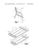
[0018] FIG. 1 is a perspective view of a side frame member that is part of a seating furniture according to an embodiment of the present invention;
[0019] FIG. 2 is a partial perspective view of a seat assembly and a backrest assembly that are part of the seating furniture of the present invention;
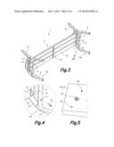
[0020] FIG. 3 is a perspective view illustrating the mounting of said seat assembly in the side frame members;
[0021] FIG. 4 is an enlarged view of detail IV of FIG. 3;
[0022] FIG. 5 is a partial perspective view of a securing element for securing a slat that is part of the backrest assembly;
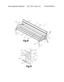
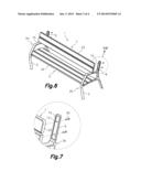
[0023] FIG. 6 is a perspective view illustrating the mounting of the backrest assembly in the side frame members;
[0024] FIG. 7 is an enlarged view of detail VII of FIG. 6;
[0025] FIG. 8 is a perspective view illustrating the securing of a complementary slat of the backrest in the side frame members; and
[0026] FIG. 9 is an enlarged view of detail IX of FIG. 8.
DETAILED DESCRIPTION OF A PREFERRED EMBODIMENT
[0027] FIG. 1 shows a side frame member 2a for a seating furniture 1 in the form of a bench according to an embodiment of the present invention. The side frame member 2a is made of cast iron and comprises two legs 3 connected at their upper ends to a seat-supporting cross member 4 and a backrest-supporting post 6 extending upwards from a back end of said seat-supporting cross member 4.
[0028] Conventionally said backrest-supporting post 6 is considerably inclined backwards.
[0029] On an upper face of the seat-supporting cross member 4 there is a first recess 9 taking up the entire width of the seat-supporting cross member 4. In said first recess 9 there are cross member through holes 11 spanning the seat-supporting cross member 4, and the function of which will be explained below.
[0030] On a front face of the backrest-supporting post 6 there is a second recess 12 in the form of a slot taking up only an intermediate region of the width of the backrest-supporting post 6. In this second recess 12 there are post through holes 13 spanning the backrest-supporting post 6, and the function of which will also be explained below.
[0031] The side frame member 2a further comprises an armrest member 15 connected to the backrest-supporting post 6 below the second recess 12, and in a portion of the backrest-supporting post 6 located below said armrest member 15 there is a complementary through hole 14 spanning the backrest-supporting post 6, and the function of which will also be explained below. In the illustrated embodiment, a front end of the armrest member 15 is connected to the front end of the seat-supporting cross member 4 by a connecting member. This armrest member 15 is optional.
[0032] FIG. 2 shows a seat assembly 5 and a backrest assembly 7. The mentioned seat assembly 5 comprises a plurality of seat slats 16 juxtaposed and parallel to one another, and first transverse planar profiles 17 that are transverse to said seat slats 16 and secured thereto by means of securing screws (not shown) inserted in corresponding securing through holes 28 formed in the first planar profiles 17 and screwed in blind securing holes 30 (FIG. 5) formed in the corresponding seat slats 16.
[0033] The seat assembly 5 includes two of said first planar profiles 17 secured near the ends of the seat slats 16, and optionally one or more first auxiliary planar profiles 17a in intermediate positions if the length of the seating furniture calls for it. Each first planar profile 17 furthermore has two mounting through holes 10 aligned with corresponding nuts 22 previously inserted in the seat slats 16 (FIG. 5). Similarly, the mentioned backrest assembly 7 comprises a plurality of backrest slats 23 juxtaposed and parallel to one another, and second transverse planar profiles 24 that are transverse to said backrest slats 23 and secured thereto by means of securing screws (not shown) inserted in corresponding securing through holes 29 formed in the second planar profiles 24 and screwed in blind securing holes 30 (FIG. 5) formed in the corresponding backrest slats 23. The backrest assembly 7 includes two of said second planar profiles 24 secured near the ends of the backrest slats 23, and optionally one or more second auxiliary planar profiles 24a in intermediate positions if the length of the seating furniture calls for it. Each second planar profile 24 furthermore has two mounting through holes 27 aligned with corresponding nuts 22 previously inserted in the backrest slats 23 (FIG. 5).
[0034] The seat slats 16 and the backrest slats 23 are preferably made of wood, and the first and second planar profiles 17, 24 are preferably made of iron. The securing through holes 28, 29 of the first and second planar profiles 17, 24 have a countersink in the top part to house the heads of the securing screws without said heads projecting from same.
[0035] The seating furniture 1 of the present invention comprises two side frame members 2a, 2b identical to the side frame member 2a described above in relation to FIG. 1, a seat assembly 5 and a backrest assembly 7 like those described above in relation to FIG. 2, and screwing elements for mounting. The two side frame members 2a, 2b, the seat assembly 5 and the backrest assembly 7 have a substantially planar configuration that allows them to be stacked, packaged, stored and transported such that they take up significantly less space than what the fully mounted seating furniture takes up. The mentioned components of the seating furniture 1 can be easily mounted by a ship-to party as explained below in relation to FIGS. 3 to 9.
[0036] FIGS. 3 and 4 illustrate the mounting of the seat assembly 5 on the two side frame members 2a, 2b. To that end, the two side frame members 2a, 2b are arranged such that they are separated from one another by a distance that is in accordance with the positions of the first planar profiles 17 in the seat assembly 5, and the seat assembly 5 is then coupled to the seat-supporting cross members 4 taking into account that the first planar profiles 17 fit in the first recesses 9 formed in the seat-supporting cross members 4 of the side frame members 2a, 2b.
[0037] Then from a lower side of the seat-supporting cross members 4 first mounting screws 18 are inserted in the cross member through holes 11 of the seat-supporting cross member 4, are passed through the mentioned mounting through holes 10 of the first planar profiles 17 of the seat assembly 5 and finally are screwed into said nuts 22 inserted in the corresponding seat slats 16.
[0038] FIGS. 6 and 7 illustrate the mounting of the backrest assembly 7 in the two side frame members 2a, 2b where the seat assembly 5 was previously mounted. To that end, the backrest assembly 7 is coupled to the backrest-supporting posts 6 taking into account that the second planar profiles 24 fit in the second recesses 12 formed in the backrest-supporting posts 6 of the side frame members 2a, 2b. Then from a back side of the backrest-supporting posts 6 second mounting screws 26 are inserted in the post through holes 13 of the backrest-supporting post 6, are passed through the mentioned mounting through holes 27 of the second planar profiles 24 of the backrest assembly 7 and finally are screwed into the nuts 22 inserted in the corresponding backrest slats 23.
[0039] The fact that the heads of the securing screws are housed in the countersinks formed in the top parts of the securing through holes 28, 29 of the first and second planar profiles 17, 24 allows correctly coupling the first and second planar profiles 17, 24 in their corresponding first and second recesses 9, 12. FIGS. 8 and 9 illustrate the mounting of a complementary backrest slat 25 preferably made of wood on the two side frame members 2a, 2b where the seat assembly 5 and the backrest assembly 7 were previously mounted. Due to the existence of the armrest members 15, the backrest of the seating furniture includes, in addition to the backrest assembly 7, the mentioned complementary backrest slat 25, the opposite ends of which are located between the armrest members 15 and the seat-supporting cross members 4.
[0040] To that end, opposite ends of the complementary backrest slat 25 are coupled to the portions of the backrest-supporting posts 6 that are located below the armrest members 15 and are secured in place by means of third mounting screws 19 that are inserted from the back side of the backrest-supporting posts 6 through the mentioned complementary holes 14 of the backrest-supporting posts 6 and are screwed into nuts inserted in the complementary backrest slat 25, similar to the nut 22 shown in FIG. 5.
[0041] Given that the armrest members 15 are optional, if the side frame members 2a, 2b did not have them, all the backrest slats could be integrated in the backrest assembly and connected by the corresponding second planar profiles, and the second slot-shaped recesses formed in the backrest-supporting posts would be sized accordingly.
[0042] It is understood that the mounting order can be changed in relation to that described above in relation to FIGS. 3 to 9.
[0043] The characteristic construction of the seating furniture of the present invention allows quickly and easily mounting the partially mounted components forming it and prevents any doubt or confusion while mounting the seating furniture with respect to the position and order of placing the seat slats 16, backrest slats 23 and complementary backrest slat 25 because they are not all equal.
[0044] In view of the attached drawings it can be seen that the side frame members 2a, 2b, the seat assembly 5 and backrest assembly 7 have an essentially planar volume, which makes it easier to package and transport them. This is also aided by the lack of appendages and projecting parts in the components, as occurs with other seating furniture or benches of the prior state.
[0045] A person skilled in the art could introduce changes and modifications in the embodiment that has been described and shown without departing from the scope of the invention as it is defined in the attached claims.
User Contributions:
Comment about this patent or add new information about this topic:
Images included with this patent application:
 |  |
 |  |
 |
| Similar patent applications: | |
| Date | Title |
|---|---|
| 2012-10-25 | Folding furniture |
| 2013-12-26 | Aquatic furniture |
| 2014-09-18 | Seat device for an aircraft or spacecraft |
| New patent applications in this class: | |
| Date | Title |
|---|---|
| 2022-05-05 | Operator's cab and work vehicle |
| 2019-05-16 | Integrated fixture retention mechanism |
| 2016-04-28 | Arm support device and method of supporting arms |
| 2016-02-25 | Belt strap of high chair for dining |
| 2015-12-17 | Method and apparatus for composite thermoplastic arm rest assembly |
| Top Inventors for class "Chairs and seats" | |
| Rank | Inventor's name |
|---|---|
| 1 | Johnathan Andrew Line |
| 2 | Larry P. Lapointe |
| 3 | Yukifumi Yamada |
| 4 | John W. Jaranson |
| 5 | Erwin Haller |