Patent application title: Counterweight powered gravity electrical generation
Inventors:
Bruce W. Burnaugh (Springfield, MO, US)
IPC8 Class: AH02K9900FI
USPC Class:
290 1 R
Class name: Prime-mover dynamo plants miscellaneous
Publication date: 2014-05-29
Patent application number: 20140145451
Abstract:
The production of electrical energy produced by the gravitational pull of
the Earth of a counter weight, which will in turn lift a drive weight so
that it can be released to the gravitational pull to mechanically turn a
generator connected by gears. This is also distinct from gravitational
equipment using only a flywheel system instead of flywheel, and moving
counter weights on rails.Claims:
1. Electrical generation using counterweight to raise drive weight
2. Electrical generation using large flywheels to sustain kinetic motion
3. Counterweight is not connected to drive shaft
4. Counterweight is electric powered rail car
5. Drive weight is attached to counterweight
6. Drive weight turns gear on drive shaft
7. Rail car drives up track from bottom of weight fall to top of weight fall
Description:
INCORPORATION BY REFERENCE
[0001] File contains cover letter, specification, abstract, claims and numerical reference sheet. Compact discs are identical--file name Counterweight Powered Gravity Electrical Generation--file size 179 kB--date of file Jun. 3, 2013.
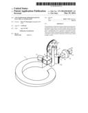
[0002] FIG. 1 shows a front view of the drive weight (5) drawn up by the counterweight, (2) which is a heavy electric rail car in an elevator (6). The railcar (2) drives up the ramp (1) to the top where it will enter the elevator (6) when pulled up by the falling of the drive weight (5) attached by a cable (3) over a pulley wheel (4). Electricity is produced by the falling of the drive weight, (5) which has a rack or series of racks (12) which rotate a pinion wheel (7) which is connected to the electrical generator (10) sending electricity through the output cable (11). To help facilitate production there is a gearbox (8) which will change the rpm of the pinion wheel (7) to a more suitable speed for the generator (10). Finally, a flywheel (9) maintains inertia. This cycle continues to repeat.
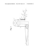
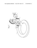
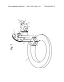
[0003] FIG. 2 shows an isometric view of the process with the electric railcar (2) at the top entering the elevator (6) and the drive weight (5) having turned the pinion wheel (7). Inertia is maintained by the flywheel, (9) while the pinion disengages and the railcar (2) enters the elevator (6).
NUMERICAL REFERENCE LIST
[0004] 1. Ramp for electric driven counterweight railcars
[0005] 2. Railcar counterweight
[0006] 3. Cable connecting drive weight to counterweight
[0007] 4. Pulley wheel supporting drive and counterweights
[0008] 5. Drive weight
[0009] 6. Counterweight elevator carriage
[0010] 7. Pinion wheel
[0011] 8. Gear reduction box
[0012] 9. Flywheel
[0013] 10. Electrical generator
[0014] 11. Electrical power cord
[0015] 12. Rack
User Contributions:
Comment about this patent or add new information about this topic:
Images included with this patent application:
 |  |
 |  |
 |
| Similar patent applications: | |
| Date | Title |
|---|---|
| 2014-07-10 | Stauffer submerged electricity generator |
| 2014-07-17 | Control system of variable speed pumped storage hydropower system and method of controlling the same |
| 2014-07-17 | Gravity and bouyancy engine driven generator |
| 2014-05-08 | Electrical generator |
| 2014-07-17 | Turbine-based energy generation system with dc output |
| New patent applications in this class: | |
| Date | Title |
|---|---|
| 2018-01-25 | Gravity-lever-actuated rotating engine |
| 2016-12-29 | Transient absorber for power generation system |
| 2016-07-07 | Power generation apparatus |
| 2016-07-07 | Modular power generator |
| 2016-05-26 | Buoyancy-driven power generation system |
| Top Inventors for class "Prime-mover dynamo plants" | |
| Rank | Inventor's name |
|---|---|
| 1 | Henrik Stiesdal |
| 2 | Per Egedal |
| 3 | Akira Yasugi |
| 4 | Takatoshi Matsushita |
| 5 | Lowell L. Wood, Jr. |