Patent application title: CAMSHAFT PHASER
Inventors:
Armin Braun (Buttenheim, DE)
Assignees:
SCHAEFFLER TECHNOLOGIES AG & CO. KG
IPC8 Class: AF01L1344FI
USPC Class:
123 9015
Class name: Internal-combustion engines poppet valve operating mechanism with means for varying timing
Publication date: 2014-05-22
Patent application number: 20140137822
Abstract:
A camshaft phaser (1), including a drive element (2) and a driven element
(3) that can be rotated relative to each other by hydraulic medium, and
the drive element (2) or the driven element (3) has sealing elements (6)
that are arranged in grooves (7) provided for this purpose, and the
groove (7) has an undercut (8) that cooperates with a complementary
geometry (12) of the sealing element (6).Claims:
1-10. (canceled)
11. A camshaft phaser comprising: a drive element; and a driven element, the drive element and the driven element having several radially oriented vanes, the drive element and the driven element forming working chambers counteracting each other, each working chamber being defined by a pair of the vanes consisting of a vane of the drive element and a vane of the driven element, the working chambers pressurizable with hydraulic medium in order to achieve a relative rotation between the drive element and the driven element, a radially oriented end face of one of the vanes having a sealing element, or a radially oriented end face of the vane being in contact with the sealing element, the sealing element being arranged in a groove of the vane, a cross section of the groove having an undercut, the sealing element extending behind the undercut.
12. The camshaft phaser as recited in claim 11 wherein the vane and the sealing element are configured in one piece.
13. The camshaft phaser as recited in claim 11 wherein the sealing element is spring-loaded.
14. The camshaft phaser as recited in claim 11 wherein the undercut is configured along an entire length of the groove.
15. The camshaft phaser as recited in claim 11 wherein the undercut is a stop in the radial direction.
16. The camshaft phaser as recited in claim 11 wherein the undercut is configured with a conical shape.
17. The camshaft phaser as recited in claim 11 wherein the undercut is configured symmetrically in the cross section of the groove.
18. The camshaft phaser as recited in claim 11 wherein the sealing element is spring-loaded and a pre-tensioning force of the spring element forces the sealing element against the undercut to limit the radial spring path.
19. A drive element or a driven element comprising: a radially oriented vane, the drive element or the driven element forming with the other of the drive element or driven element working chambers counteracting each other, each working chamber being defined by a pair of the vanes consisting of a vane of the drive element and a vane of the driven element, the working chambers pressurizable with hydraulic medium in order to achieve a relative rotation between the drive element and the driven element, a radially oriented end face of one of the vanes having a sealing element, or a radially oriented end face of the vane being in contact with the sealing element, the sealing element being arranged in a groove of the vane, a cross section of the groove having an undercut, the sealing element extending behind the undercut.
20. A sealing element of a camshaft phaser, the sealing element comprising an extension, the sealing element being arranged in a groove of the vane, a cross section of the groove having an undercut, the extension extending behind the undercut, the vane being part of the drive or driven element as recited in claim 19.
Description:
[0001] The invention relates to a camshaft phaser.
BACKGROUND OF THE INVENTION
[0002] Camshaft phasers are used in internal combustion engines in order to vary the timing of the combustion chamber valves so that the phase relation between the crankshaft and the camshaft can be configured variably within a defined angular range, between a maximum early position and a maximum late position. Adapting the timing to the current load and rotational speed lowers fuel consumption and reduces emissions. For this purpose, camshaft phasers are integrated into a power train via which a torque is transmitted from the crankshaft to the camshaft. This power train can be configured, for instance, as a belt drive, chain drive or gear drive.
[0003] In a hydraulic camshaft phaser, the driven element and the drive element form one or more pair of vanes pairs of pressure chambers that counteract each other and that can be pressurized with oil. Here, the drive element and the driven element are arranged coaxially. A relative movement is generated between the drive element and the driven element by filling and emptying individual pressure chambers. The spring, which has a rotational effect between the drive element and the driven element, forces the drive element relative to the driven element in a preferential direction. This preferential direction can be the same as or opposite to the direction of rotation.
[0004] A widespread design of the hydraulic camshaft phaser is the vane-type adjuster. Vane-type adjusters have a stator, a rotor and a drive element. The rotor is usually non-rotatably joined to the camshaft and forms the driven element. The stator and the drive element are likewise non-rotatably joined to each other and, if applicable, are configured in one piece. Here, the rotor is located coaxially to the stator and inside the stator. The rotor and the stator, with their radially extending vanes, form oil chambers that counteract each other, that can be pressurized with oil and that permit a relative movement between the stator and the rotor. The vanes are either configured in one piece with the rotor or the stator and/or they are provided as "inserted vanes" in grooves in the rotor or stator that are provided for this purpose. Moreover, the vane-type adjusters have various sealing covers. The stator, the drive element and the sealing cover are secured by means of several screwed connections.
[0005] German patent application DE 199 63 094 A1 describes a camshaft phaser in which the vanes are configured as spring-loaded, thin sheet metal. These spring-loaded, thin vanes permit a high adjustment angle and, at the same time, due to the spring-loading, they integrate a sealing function between the two working chambers.
SUMMARY OF THE INVENTION
[0006] It is an object of the present invention to provide a camshaft phaser whose sealing elements are configured to create a seal between the working chambers in an easy-to-install and reliable manner.
[0007] The present invention provides a camshaft phaser including a drive element and a driven element, whereby the drive element and the driven element have several radially oriented vanes, whereby the drive element and the driven element form working chambers that counteract each other, hereby each working chamber is defined by a pair of vanes consisting of a vane (4) of the drive element and a vane of the driven element, whereby the working chambers can be pressurized with hydraulic medium in order to achieve a relative rotation between the drive element and the driven element, whereby a radially oriented end face of the vane has sealing elements, or a radially oriented end face of a vane is in contact with a sealing element, whereby the sealing element is arranged in a groove of the vane, characterized in that a cross section of the groove has an undercut behind which the sealing element extends.
[0008] This achieves that the undercut of the groove cooperates with a complementary geometry of the sealing element in such a way that a path delimitation is achieved in the radial direction. The sealing elements can be installed without external installation equipment from an axial end face of the drive element or of the driven element, and they are secured in the radial direction by the undercut according to the invention. This is particularly advantageous in the case of spring-loaded sealing elements.
[0009] The sealing elements are preferably made of plastic. As an alternative they sealing elements can be made of metal. In addition to the material employed, a coating can also be provided.
[0010] The undercut according to the invention can extend along the entire length or over part of the entire length of the groove. By the same token, the complementary geometry of the sealing element can be configured partially or over the entire length of the sealing element.
[0011] In one embodiment of the invention, the sealing element is configured in one piece with the vanes. The vane is, at the same time, the sealing element and can be placed into the groove of the drive element or of the driven element. Such vanes are configured as thin-walled separating elements that can advantageously be made of sheet metal. The vane or the sealing element has a geometry that is complementary to the undercut. A pre-tensioning force of a spring element forces the vane or the sealing element in the radial direction, thereby forcing the complementary geometry against the undercut according to the invention. The undercut according to the invention is provided as the maximum path delimitation in the radial direction. In the assembled state of the driven element with the drive element, a residual distance is preferably provided between the undercut and the complementary geometry of the sealing element. The vanes or sealing elements are pushed into the groove in the axial direction. Materials such as plastic and/or metal can be provided for the vanes or for the sealing element. In addition to the material employed, a coating can also be provided.
[0012] In one advantageous embodiment, the sealing element is configured to be spring-loaded. The sealing element is arranged on one radial end face of a vane. Spring-loaded sealing elements advantageously compensate for coaxiality errors between the drive element and the driven element. The undercut according to the invention is provided as the maximum path delimitation in the radial direction. In the installed state of the driven element with the drive element, preferably a residual distance is provided between the undercut and the complementary geometry of the sealing element.
[0013] In one embodiment of the invention, the undercut can be configured along the entire length of the groove. As an alternative to this, part of the groove can be provided as the undercut. A configuration of the undercut along the entire length of the groove is advantageous for the formation of the complementary geometry of the sealing element over its entire length, since, thanks to the widening of the sealing element due to the complementary geometry, more installation space is available for a spring element that can be positioned into a pocket of the sealing element provided for this purpose. The spring element can thus likewise be made to be larger and to have a greater spring force.
[0014] In an especially preferred embodiment, the undercut is provided as a radial stop. Advantageously, the sealing elements can be placed on the drive element or on the driven element in the groove and they are positioned so as to be captive in the groove before the drive element with the driven element is installed. It is accordingly advantageous if the sealing element and the vanes are configured in one piece. The vanes or the sealing elements are preferably configured to be thin-walled and are likewise pre-installed along with the drive element or the driven element so as to be captive.
[0015] In one embodiment of the invention, the undercut has a conical shape. A conical shape has a larger contact surface between the sealing element and the undercut. A conical shape of the undercut configured on one side on the groove can facilitate the positioning of the sealing element on a delimitation wall of the groove. The additional spring-loading of the sealing element brings the sealing element into contact with a delimitation wall of a groove, already in the pre-installed state. Therefore, this can advantageously counteract a contact change in the groove when the direction of adjustment of the camshaft phaser is changed. The same effect can be applied to a sealing element that is configured in one piece with the vane.
[0016] As an alternative, various linear and non-linear undercut geometries are conceivable.
[0017] In another embodiment of the invention, the undercut is configured symmetrically in the cross section of the groove. Additional spring-loading facilitates the centering of the sealing element in the groove. The same effect can be transferred to a sealing element configured in one piece with the vane.
[0018] For this purpose, various linear and non-linear undercut geometries are conceivable.
[0019] As an alternative, all kinds of undercut geometries can be implemented in a groove or in a plurality of grooves.
[0020] The undercut can be produced in the groove by means of milling, sintering, casting, grinding and the like. Undercuts that are not configured in one piece with the drive element or with the driven element can be formed by additional elements such as platelets, cuffs and the like, together with a simple groove of the drive element or of the driven element. Numerous geometries for the cross section of the groove are conceivable such as, for instance, rectangular, circular and the like.
[0021] In one configuration of the invention, the sealing element is spring-loaded, whereby the pre-tensioning force of the spring element forces the sealing element against the undercut of the groove, thereby limiting the radial spring path. Advantageously, the sealing elements can be placed on the drive element or on the driven element in the groove, and they are positioned so as to be captive in the groove before the drive element with the driven element is installed. It is accordingly advantageous for the sealing element and the vanes to be configured in one piece. The vanes or the sealing elements are preferably configured to be thin-walled and are likewise pre-installed so as to be captive with the drive element or the driven element.
[0022] The arrangement according to the invention of an undercut in a groove that accommodates a sealing element or a vane facilitates the pre-installation. Moreover, a poka yoke effect can be achieved, as a result of which an unambiguous positional orientation can be ensured by the complementary geometry on the sealing element, for example, during the insertion during the installation.
BRIEF DESCRIPTION OF THE DRAWINGS
[0023] An embodiment of the invention is shown in the following figure.
[0024] The figure shows the following:
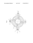
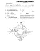
[0025] FIG. 1 a driven element with an installed sealing element.
DETAILED DESCRIPTION
[0026] FIG. 1 shows a driven element 3 with an installed sealing element 6. The driven element 3 is configured as an impeller, whereby four vanes 4 distributed along the circumference are shaped in one piece with the driven element 3 (rotor) and they extend in the radial direction 10 away from a hub 11. The vanes 4 divide the counteracting working chambers A, B, their spatial delimitations, as known from the state of the art, by a stator or drive element 2 (not shown here) that has radially extending vanes and that is optionally augmented by additional side covers 15. The hub 11 is provided for purposes of a non-rotatable attachment to a camshaft 16 (not shown here) or to an adapter part for the camshafts 16. Grooves 7 that each have an undercut 8 are formed on the radial end faces 5 of the vanes 4. In one groove 7, the sealing element 6 is already pre-installed. The sealing element 6 is configured as a plastic strip. The complementary geometry 12 of the sealing element 6 extends behind the undercut 8. The groove 7 has a rectangular shape with a linear groove bed 13 and linear delimitation surfaces 14 that serve to guide the sealing element in the groove 7. The delimitation surfaces 14 form a contact surface for the sealing element 6 during the operation of the camshaft phaser. The cross section of the groove 7 extends over the entire axial length of the drive element 3. There is a spring element 9 (not shown here) that is arranged inside the sealing element 6 and that pushes the sealing element 6 in the radial direction 10 outwards and thus against the undercut 8.
LIST OF REFERENCE NUMERALS
[0027] 1 camshaft phaser
[0028] 2 drive element
[0029] 3 driven element
[0030] 4 vanes
[0031] 5 radial end face
[0032] 6 sealing element
[0033] 7 groove
[0034] 8 undercut
[0035] 9 spring element
[0036] 10 radial direction
[0037] 11 hub
[0038] 12 complementary geometry
[0039] 13 groove bed
[0040] 14 delimitation surface
[0041] 15 side cover
[0042] 16 camshaft
User Contributions:
Comment about this patent or add new information about this topic:
Images included with this patent application:
 |  |
| Similar patent applications: | |
| Date | Title |
|---|---|
| 2013-11-28 | Camshaft phaser |
| 2014-01-23 | Camshaft phaser |
| 2013-07-18 | Camshaft adjuster |
| 2013-07-18 | Camshaft adjuster |
| 2013-08-08 | Camshaft adjuster |
| New patent applications in this class: | |
| Date | Title |
|---|---|
| 2018-01-25 | Split axial cam shifting system variable valve actuation functions |
| 2016-12-29 | Motor vehicle, control unit and method for controlling a phase angle of a camshaft |
| 2016-12-29 | Valve timing control device for internal combustion engine and controller for valve timing control device |
| 2016-12-29 | Apparatus for opening and closing channel |
| 2016-12-29 | Rotation control apparatus of cvvt |
| New patent applications from these inventors: | |
| Date | Title |
|---|---|
| 2013-08-22 | Rotor for a camshaft adjuster, and camshaft adjusting system |
| 2013-07-18 | Camshaft adjuster for an internal combustion engine |
| 2013-04-04 | Rotor for a camshaft adjuster and camshaft adjuster |
| Top Inventors for class "Internal-combustion engines" | |
| Rank | Inventor's name |
|---|---|
| 1 | Ross Dykstra Pursifull |
| 2 | Gopichandra Surnilla |
| 3 | Joseph Norman Ulrey |
| 4 | Thomas G. Leone |
| 5 | Chris Paul Glugla |