Patent application title: UTILITY HARNESS
Inventors:
Kris Alan Mcbride (Emmett, ID, US)
Assignees:
ZEHI, INC.
IPC8 Class: AA45F314FI
USPC Class:
224600
Class name: Carried by animate bearer article held by receiver flaccid attaching means looped around neck or crossing shoulder
Publication date: 2014-05-15
Patent application number: 20140131411
Abstract:
An utility harness designed to allow an individual wearing the harness to
ascend and/or descend a ladder, while maintaining three points of contact
with the ladder, while accessories and equipment are attached to the
utility harness.Claims:
1. A utility harness for wearing by a wearer having a body, said harness
comprising a belt portion and at least one shoulder strap portion, said
harness further comprising: said belt portion comprising a body portion
and a strap portion; said body portion having an inner surface and an
outer surface, said inner surface configured for contacting the body of
the wearer, whereas the outer surface is configured for facing outwards
from the body of the wearer; said strap portion comprising a first end
and a second end, wherein said first end terminates in a first connector,
and said second end terminates in a second connector, said first
connector and said second connector configured for engaging with one
another; said shoulder strap portion comprising at least one shoulder
strap, said shoulder strap having a front belt and a rear belt, said
front belt attaching to a front side of said belt portion, said rear belt
attaching to a rear side of said belt portion; and said at least one
shoulder strap portion comprising a top shoulder connector assembly
configured for securing an object to be carried to said shoulder strap.
2. The utility harness of claim 1, wherein said top shoulder connector assembly comprising an open channel shape configured for receiving at least a portion of said object therein, and a lock clip for closing said open channel shape and retaining said at least a portion of said object in said open channel.
3. The utility harness of claim 2, wherein: said top shoulder connector assembly further comprises a base portion, a first leg portion, a second leg portion, a lower cover portion, an upper cover portion, and a lock clip; said second leg portion comprises a lock flange; and said lock clip comprises a lock port configured for receiving the lock flange therethrough.
4. The utility harness of claim 3, wherein said top shoulder connector assembly further comprises a non-slip material portion for preventing an object locked within said top shoulder connector assembly from slipping.
5. A utility harness for wearing by a wearer having a body, said harness comprising: a belt portion, and a shoulder strap portion; said belt portion comprising a body portion, and a strap portion; said body portion having an inner surface and an outer surface, said inner surface configured for contacting the body of the wearer, whereas the outer surface is configured for facing outwards from the body of the wearer; said strap portion comprising a first end and a second end, wherein said first end terminates in a first connector, and said second end terminates in a second connector, said first connector and said second connector configured for engaging with one another to fit around the body of the wearer; and said shoulder strap portion comprising at least one shoulder strap, said shoulder strap having a front belt and a rear belt, said front belt attaching to a front side of said belt portion, said rear belt attaching to a rear side of said belt portion.
6. The utility harness of claim 5, further comprising a coil carrier, said coil carrier comprising first strap terminating in a connector, and a second strap terminating in a connector, said first strap extending through said coil carrier and connecting with said connector, said second strap extending through said coil carrier and connecting with said connector, said coil carrier configured for carrying a coil of an elongated material therein.
7. The utility harness of claim 5, wherein said front belt comprises a shoulder strap portion first connector, and said rear belt comprises a shoulder strap portion second connector.
8. The utility harness of claim 7, wherein said belt portion further comprises a front shoulder strap connector and a rear shoulder strap connector, said front shoulder strap connector for connecting with said shoulder strap portion first connector, said rear shoulder strap connector for connecting with said shoulder strap portion second connector.
9. The utility harness of claim 7, wherein said belt portion comprises a first front shoulder strap connector, a second front shoulder strap connector, a first rear shoulder strap connector, and a second rear shoulder strap connector; and wherein said shoulder strap comprises a first shoulder strap and a second shoulder strap, said first shoulder strap having a front belt and a rear belt, said first shoulder strap front belt attaching to said first front shoulder strap connector, said first shoulder strap rear belt attaching to said first rear shoulder strap connector, said second shoulder strap having a front belt and a rear belt, said second shoulder strap front belt attaching to said second front shoulder strap connector, said second shoulder strap rear belt attaching to said second rear shoulder strap connector.
10. The utility harness of claim 5, wherein said belt portion comprises a first front shoulder strap connector, a second front shoulder strap connector, a first rear shoulder strap connector, and a second rear shoulder strap connector; and wherein said at least one shoulder strap comprises a first shoulder strap comprising a first end and a second end, and a second shoulder strap comprising a first end and a second end; and wherein said first and second ends comprise connectors configured for mating with said shoulder strap connectors.
11. The utility harness of claim 5, wherein said at least one shoulder strap comprises a first shoulder strap and a second shoulder strap.
12. The utility harness of claim 11, wherein said first shoulder strap comprises a first strap body, a front belt, and a rear belt; wherein said front belt comprises a first end for connecting with said belt portion, and a second end for connecting with said first strap body; wherein said rear belt comprises a first end for connecting with said belt portion, and a second end for connecting with said first strap body; wherein said second shoulder strap comprises a second strap body, a front belt and a rear belt; wherein said front belt comprises a first end for connecting with said belt portion, and a second end for connecting with said second strap body; and wherein said rear belt comprises a first end for connecting with said belt portion, and a second end for connecting with said second strap body.
13. The utility harness of claim 11, wherein said first shoulder strap comprises a single belt having a first end for connecting with said front side of said belt portion, and a second end for connecting with said rear side of said belt portion; and wherein said second shoulder strap comprises a single belt having a first end for connecting with said front side of said belt portion, and a second end for connecting with said rear side of said belt portion.
14. The utility harness of claim 5, wherein at least one of said shoulder straps comprises a top shoulder connector assembly connected thereto, said top shoulder connector assembly for securing an object to said utility harness.
15. The utility harness of claim 14, wherein said top shoulder connector assembly comprises an open channel shape configured for receiving at least a portion of said object therein, and a lock clip for closing said open channel shape and retaining said at least a portion of said object in said open channel.
16. The utility harness of claim 15, wherein: said top shoulder connector assembly further comprises a base portion, a first leg portion, a second leg portion, a lower cover portion, an upper cover portion, and a lock clip; said second leg portion comprises a lock flange; and said lock clip comprises a lock port configured for receiving the lock flange therethrough.
17. The utility harness of claim 14, wherein said top shoulder connector assembly comprises a non-slip material portion for preventing an object locked within said top shoulder connector assembly from slipping.
18. The utility harness of claim 5, further comprising: at least one accessory connector for the attachment of an accessory thereto; and a belt connector strap for connecting an object to said utility harness, said belt connector strap comprising a connector configured for engaging said accessory connector, a strap, and a clip configured for receiving said object to be carried.
19. The utility harness of claim 18, further comprising a forked strap for connecting an object to said utility harness, said forked strap comprising a connector configured for engaging said accessory connector, a strap, and at least one accessory connection configured for connecting with an accessory object to be carried, wherein said accessory connection comprises a hook and loop fastener portion, and a non-slip material portion.
20. The utility harness of claim 18, further comprising a wrapping connector assembly, said wrapping connector assembly comprising a strap having a connector for attaching with said accessory connector and a free end, said wrapping connector assembly further comprising a buckle able to receive the free end of said wrapping connector assembly therethrough, said strap further comprising one or more hook and loop fastener portions, and a non-slip material portion.
Description:
TECHNICAL FIELD
[0001] The disclosure generally relates to utility harnesses. Particular embodiments relate to utility harnesses for use in satellite dish installation to facilitate compliance with Occupational Safety & Health Administration (OSHA) regulations.
BACKGROUND
[0002] Satellite dishes have become increasingly prevalent on residential and commercial buildings. Satellite dish installation requires the use of ladders to access building roofs and walls to mount satellite dish equipment. In order to install satellite dishes, installers routinely carry various objects, including tools, cabling, materials, and equipment, while ascending and/or descending ladders. Installers routinely carry one or more of these items in one of their hands while ascending/descending a ladder, thereby failing to maintain the OSHA mandated three points of contact with the ladder. As a result, installers are at great risk for physical injury from lost balance and falls from ladders.
SUMMARY OF THE DISCLOSURE
[0003] Several exemplary harnesses are described herein.
[0004] Additional understanding of the devices and methods contemplated and/or claimed by the inventor can be gained by reviewing the detailed description of exemplary devices and methods, presented below, and the referenced drawings.
BRIEF DESCRIPTION OF THE DRAWINGS
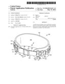
[0005] FIG. 1 is a perspective view of a first exemplary harness.
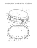
[0006] FIG. 2 is a plan view of the first exemplary harness of FIG. 1.
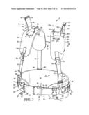
[0007] FIG. 3 is a front perspective view of a second exemplary harness, illustrating a first exemplary top shoulder connector assembly.
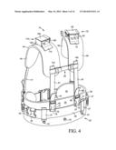
[0008] FIG. 4 is a rear perspective view of the second exemplary harness of FIG. 3, illustrating a first exemplary top shoulder connector assembly.
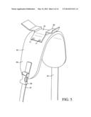
[0009] FIG. 5 is a partial, perspective view of the exemplary harness of FIG. 3, illustrating a second exemplary top shoulder connector assembly.
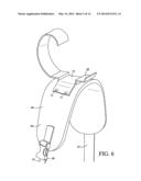
[0010] FIG. 6 is a partial, perspective view of the exemplary harness of FIG. 3, illustrating a third exemplary top shoulder connector assembly.
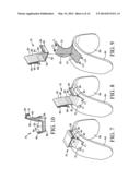
[0011] FIG. 7 is a partial, perspective view of the first exemplary top shoulder connector assembly of the exemplary harness of FIG. 3.
[0012] FIG. 8 is a partial, perspective view of the first exemplary top shoulder connector assembly of the exemplary harness of FIG. 3.
[0013] FIG. 9 is a partial, perspective view of the first exemplary top shoulder connector assembly of the exemplary harness of FIG. 3.
[0014] FIG. 10 is a perspective view of one of the top shoulder connector assemblies of FIG. 3.
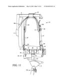
[0015] FIG. 11 is a right side view of the exemplary harness of FIG. 3, illustrating attachment of a satellite dish.
[0016] FIG. 12 is a plan view of a connector assembly.
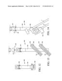
[0017] FIG. 13 is a plan view of another connector assembly.
[0018] FIG. 14 is a second plan view of the connector assembly of FIG. 13.
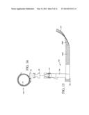
[0019] FIG. 15 is a plan view of another connector assembly.
[0020] FIG. 16 is a cross-sectional view of the connector assembly of FIG. 15.
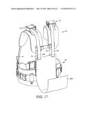
[0021] FIG. 17 is a rear perspective view of the exemplary harness of FIG. 3, illustrating a coil carrier.
[0022] FIG. 18 is a front perspective view of the exemplary harness of FIG. 3, further illustrating the coil carrier of FIG. 17.
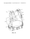
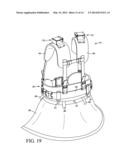
[0023] FIG. 19 is a rear perspective view of the exemplary harness of FIG. 3 including a deployed rain fly.
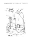
[0024] FIG. 20 is a rear perspective view of the exemplary harness of FIG. 3, illustrating a stowed rain fly.
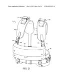
[0025] FIG. 21 is a front perspective view of the exemplary harness of FIG. 3, illustrating a front pouch.
DETAILED DESCRIPTION
[0026] The following description and the referenced drawings provide illustrative examples of that which the inventor regards as his invention. As such, the embodiments discussed herein are merely exemplary in nature and are not intended to limit the scope of the invention, or its protection, in any manner. Rather, the description and illustration of these embodiments serve to enable a person of ordinary skill in the relevant art to practice the invention.
[0027] The use of "e.g.," "etc," "for instance," "in example," "for example," and "or" and grammatically related terms indicates non-exclusive alternatives without limitation, unless otherwise noted. The use of "including" and grammatically related terms means "including, but not limited to," unless otherwise noted. The use of the articles "a," "an" and "the" are meant to be interpreted as referring to the singular as well as the plural, unless the context clearly dictates otherwise. Thus, for example, reference to "a shoulder strap" includes two or more such shoulder straps, and the like. The use of "optionally," "alternatively," and grammatically related terms means that the subsequently described element, event or circumstance may or may not be present/occur, and that the description includes instances where said element, event or circumstance occurs and instances where it does not. The use of "preferred," "preferably," and grammatically related terms means that a specified element or technique is more acceptable than another, but not that such specified element or technique is a necessity, unless the context clearly dictates otherwise. The use of "exemplary" means "an example of" and is not intended to convey a meaning of an ideal or preferred embodiment.
[0028] The term "belt," as used herein, means an elongated, flat strip of material, unless the context clearly dictates otherwise.
[0029] FIGS. 1 and 2 illustrate a first exemplary harness 100. The harness 100 comprises several components designed to function as a system to allow an individual wearing the harness (the "wearer") to ascend and/or descend a ladder, while maintaining three points of contact with the ladder, while accessories and equipment are attached to the utility harness.
[0030] The harness 100 comprises a belt portion 120. The belt portion 120 is preferably a mid-waist belt, comprising a wide, padded belt with a front-side connector, such as a release buckle 121. The belt portion 120 is designed to fit the wearer above the waist, along the lower part of the rib cage, thereby providing lumbar support to the lumbar spine of the wearer. The belt portion 120 comprising a body portion 122 and a strap portion 123.
[0031] The body portion 122 having an inner surface 124 and an outer surface 125. The inner surface 124 for contacting the body of the wearer, whereas the outer surface 125 facing outwards from the body of the wearer.
[0032] As illustrated in FIGS. 1 and 2, the body portion 122 comprises a plurality of connectors 127 located on the outer surface 125 for connecting with a belt 128 of the strap portion 123. While the connectors 127 illustrated are belt loops, other types of connectors could alternatively be used, including but not limited to mechanical fasteners, fasteners, adhesives, and sewing.
[0033] The strap portion 123 comprises at least one belt 128. The belt 128 having a first end 129 extending to a second end 139. Alternatively, the belt 128 could comprise a plurality of belts or other connectors. In the illustrated harness, the first end 129 terminates in a first connector 126, and the second end 139 terminates in a second connector 138. The illustrated first connector 126 and second connector 138 comprising nylon snap buckles. Other types of connectors could alternatively be used instead of nylon snap buckles, including but not limited to mechanical fasteners, fasteners, adhesives, and sewing. A skilled artisan will be able to select an appropriate type of connector and material for the connectors in a particular embodiment based on various considerations, including the intended use of the harness, the intended arena within which the harness will be used, and the equipment and/or accessories with which the harness is intended to be used, among other considerations. These first and second connectors (126, 138) for engaging with one another. It is preferred that at least one of the connectors be adjustable, for adjusting the length of the belt portion 123.
[0034] The belt portion 120 preferably further comprises at least one accessory connector 130 for the attachment of parts, tools, equipment, and related materials to the belt portion 120. The illustrated belt portion 120 comprising one or more accessory connectors 130, 131, 134, 136, 135, 137. These accessory connectors for connecting with accessories and/or mating connectors connecting with accessories (not illustrated), for instance tools, cabling, materials, and equipment. The illustrated accessory connectors comprising nylon snap buckles. Other types of connectors could alternatively be used instead of nylon snap buckles, including but not limited to mechanical fasteners, fasteners, adhesives, and sewing. A skilled artisan will be able to select an appropriate type of connector and material for the connectors in a particular embodiment based on various considerations, including the intended use of the harness, the intended arena within which the harness will be used, and the equipment and/or accessories with which the harness is intended to be used, among other considerations.
[0035] It is envisioned that the accessory connectors would be connected to the body portion 122 or the belt 128 via sewing. Other manners of connecting the accessory connectors could be used, including but not limited to mechanical fasteners, fasteners, and adhesives. A skilled artisan will be able to select an appropriate type of connector and material for the connectors in a particular embodiment based on various considerations, including the intended use of the harness, the intended arena within which the harness will be used, and the equipment and/or accessories with which the harness is intended to be used, among other considerations.
[0036] FIGS. 3 through 21 illustrate a second exemplary harness 10. The harness 10 comprises several components designed to function as a system to allow an individual wearing the harness (the "wearer") to ascend and/or descend a ladder, while maintaining three points of contact with the ladder. The second exemplary harness 10 comprises a belt portion 20, and a shoulder strap portion 40.
[0037] The belt portion 20 is preferably a mid-waist belt, comprising a wide, padded belt with a front-side connector, such as a release buckle 21. The belt portion 20 is designed to fit the wearer above the waist, along the lower part of the rib cage, thereby providing lumbar support to the lumbar spine of the wearer. The belt portion 20 comprising a body portion 22 and a strap portion 23.
[0038] The body portion 22 having an inner surface 24 and an outer surface 25. The inner surface 24 for contacting the body of the wearer, whereas the outer surface 25 facing outwards from the body of the wearer. As illustrated in the figures, the body portion 22 comprises a plurality of connectors 27 located on the outer surface 25 for connecting with a belt 28 of the strap portion 23. While the connectors 27 illustrated are belt loops, other types of connectors could alternatively be used, including but not limited to mechanical fasteners, fasteners, adhesives, and sewing.
[0039] The strap portion 23 comprises at least one belt 28. The belt 28 having a first end 29 extending to a second end 39. Alternatively, the belt 28 could comprise a plurality of belts or other connectors. In the illustrated harness, the first end 29 terminates in a first connector 26, and the second end 39 terminates in a second connector 38. The illustrated first connector 26 and second connector 38 comprising nylon snap buckles. Other types of connectors could alternatively be used instead of nylon snap buckles, including but not limited to mechanical fasteners, fasteners, adhesives, and sewing. A skilled artisan will be able to select an appropriate type of connector and material for the connectors in a particular embodiment based on various considerations, including the intended use of the harness, the intended arena within which the harness will be used, and the equipment and/or accessories with which the harness is intended to be used, among other considerations. These first and second connectors (26, 38) for engaging with one another. It is preferred that at least one of the connectors be adjustable, for adjusting the length of the strap portion 23.
[0040] The belt portion 20 preferably further comprises at least one accessory connector for the attachment of parts, tools, equipment, and related materials to the belt portion 20. The illustrated belt portion comprising a number of accessory connectors, including accessory connectors 30, 31, 34, 36, 35, and 37. These accessory connectors for connecting with accessories and/or mating connectors connecting with accessories, for instance tools, cabling, materials, and equipment. The illustrated accessory connectors comprising nylon snap buckles. Other types of connectors could alternatively be used instead of nylon snap buckles, including but not limited to mechanical fasteners, fasteners, adhesives, and sewing. A skilled artisan will be able to select an appropriate type of connector and material for the connectors in a particular embodiment based on various considerations, including the intended use of the harness, the intended arena within which the harness will be used, and the equipment and/or accessories with which the harness is intended to be used, among other considerations.
[0041] It is envisioned that the accessory connectors would be connected to the belt portion 20 or the belt 28 via sewing. Other types of connectors could alternatively be used instead of nylon snap buckles, including but not limited to mechanical fasteners, fasteners, adhesives, and sewing. A skilled artisan will be able to select an appropriate type of connector and material for the connectors in a particular embodiment based on various considerations, including the intended use of the harness, the intended arena within which the harness will be used, and the equipment and/or accessories with which the harness is intended to be used, among other considerations.
[0042] The belt portion 20 further comprising at least one shoulder strap connector for connecting with a shoulder strap. The illustrated harness 10 having a first shoulder strap connector 32, a second shoulder strap connector 46, a third shoulder strap connector 55, and a fourth shoulder strap connector 51. These shoulder strap connectors comprising nylon snap buckles. These connectors (32, 46, 55, 51) for engaging with mating connectors (33, 47, 56, 49) attaching to the shoulder straps (described below). These connectors (32, 46, 55, 51) may attach to the belt portion 20 on outer surface 25 by a belt (91, 78, 76, 73) having an end (92, 79, 77, 74) terminating in connectors (32, 46, 55, 51). Alternately, these connectors (32, 46, 55, 51) may attach to the belt portion 20 on belt 28 of strap portion 23 by a belt (91, 78, 76, 73) having an end (92, 79, 77, 74) terminating in connectors (32, 46, 55, 51). A skilled artisan will be able to select an appropriate type of connector and material for the connectors in a particular embodiment based on various considerations, including the intended use of the harness, the intended arena within which the harness will be used, and the equipment and/or accessories with which the harness is intended to be used, among other considerations. Other types of connectors could alternatively be used instead of nylon snap buckles, including but not limited to mechanical fasteners, fasteners, adhesives, and sewing.
[0043] In the second exemplary harness 10, the shoulder strap portion 40 comprises a first shoulder strap 44 and a second shoulder strap 64. In exemplary harnesses, more or less shoulder straps could be provided.
[0044] The first shoulder strap 44 comprising a front belt 41 having a first end 42 for connecting with the belt portion 20, and a second end 142 for connecting with the body of the first shoulder strap 44. The first shoulder strap 44 further comprising a rear belt 81 having a first end 43 for connecting with the belt portion 20, and a second end 143 for connecting with the body of the first shoulder strap 44. The second shoulder strap 64 comprising a front belt 57 having a first end 54 for connecting with the belt portion 20, and a second end 154 for connecting with the body of the second shoulder strap 64. The second shoulder strap 64 further comprising a rear belt 87 having a first end 48 for connecting with the belt portion 20, and a second end 148 for connecting with the body of the second shoulder strap 64.
[0045] Alternatively, the first shoulder strap 44 could comprise a single belt having a first end for connecting with the front side of the belt portion, and a second end for connecting with the second side of the belt portion; and/or the second shoulder strap 64 could comprise a single belt having a first end for connecting with the front side of the belt portion, and a second end for connecting with the second side of the belt portion. The ends of these single belts could connecting to the same side of the belt portion, in other embodiments one of the first end or second end may connect to the opposite side of the belt portion (e.g., crossing over on the back of the wearer).
[0046] In the illustrated harness 10, the first end 42 of front belt 41 is illustrated as terminating in a releasable connector 33, the first end 43 of rear belt 81 is illustrated as terminating in a releasable connector 47, the first end 54 of front belt 57 is illustrated as terminating in a releasable connector 56, and the first end 48 of belt 87 is illustrated as terminating in a releasable connector 49. It is preferred that these releasable connectors comprise nylon snap buckles. These connectors (33, 47, 56, 49) for engaging with mating connectors (32, 46, 55, 51) attaching to the belt portion 20 (described above). It is preferred that at least one of the connectors (33, 47, 56, 49) be adjustable, for adjusting the length of the shoulder straps. A skilled artisan will be able to select an appropriate type of connector and material for the connectors in a particular embodiment based on various considerations, including the intended use of the harness, the intended arena within which the harness will be used, and the equipment and/or accessories with which the harness is intended to be used, among other considerations. Other types of connectors could alternatively be used instead of nylon snap buckles, including but not limited to mechanical fasteners, fasteners, adhesives, and sewing.
[0047] It is preferred that the shoulder straps 44, 64 are padded, for instance through use of padded portion 45 and padded portion 59.
[0048] The shoulder straps 44, 64 can further comprise accessory connectors 53, 58 configured for allowing accessories to be connected to the shoulder strap(s). The accessory connectors illustrated in the figures attaching to the front side of the second exemplary harness 10. In other exemplary harnesses, one or more accessory connectors may be located on other portions of the harness, including but not limited to the back side of the harness.
[0049] As illustrated in FIG. 4, the shoulder strap portion 40 further comprises a lateral stabilizer 50 for stabilizing the lateral separation of the first shoulder strap 44 from the second shoulder strap 64. The lateral stabilizer 50 may be adjustable, for adjusting the distance between the first shoulder strap 44 and the second shoulder strap 64.
[0050] FIGS. 3 and 4 also illustrating the provision of one or more rain fly connectors 61 for allowing a rain fly 99 (illustrated in FIGS. 19 and 20) for covering/protecting a separate utility belt to be connected thereto. While the rain fly connectors illustrated in this figure comprise snap connectors, a skilled artisan will be able to select an appropriate structure and material for the rain fly connectors in a particular embodiment based on various considerations, including the intended use of the harness, the intended arena within which the harness will be used, and the equipment and/or accessories with which the harness is intended to be used, among other considerations.
[0051] In exemplary harnesses, a rain fly 99 may or may not be present. As illustrated in FIGS. 19 and 20, the rain fly 99 (or the harness 10) may further comprise one or more rain fly tie-town straps 98 for allowing the rain fly 99 to be rolled up and stored (as illustrated in FIG. 20).
[0052] As illustrated in FIGS. 3, 4, and 17 through 21, the first shoulder strap 44 comprises a top shoulder connector assembly 170, and the second shoulder strap 64 comprises a top shoulder connector assembly 70. The top shoulder connector assemblies 70, 170 are for securing one or more objects to be carried, for instance a satellite dish arm (illustrated in FIG. 11), to the shoulder of the wearer and/or the shoulder strap.
[0053] It is preferred that the top shoulder connector assemblies described and illustrated herein be removable, however in some exemplary harnesses, the top shoulder connector assemblies may be fixed in place.
[0054] Referring particularly to FIGS. 7 through 10, the top shoulder connector assembly 170 is attached to the shoulder strap 64 via a fastener strap 72, the fastener strap 72 having a first end extending to a second end. It is preferred that the fastener strap 72 be releasably attached to the shoulder strap 64, for instance through one or more snaps or other fasteners 71, 171. It is preferred that the fastener strap 72 further comprise a slip-resistant gripping material portion for preventing the slippage of the object held therein.
[0055] The top shoulder connector assembly 170 comprises a base portion 82, a first leg portion 83, a second leg portion 84, a lower cover portion 60, an upper cover portion 65 and a lock clip 85.
[0056] The base portion 82 is configured to be received between the shoulder strap 64 and the fastener strap 72, and is thereby attached to the shoulder strap 64 when the fastener strap 72 is fastened at the fasteners 71. The second exemplary harness 10 illustrated in the Figures comprising a plurality of hook-and-loop (e.g., VELCRO) style fasteners utilized to more securely attach components together. For instance, the inside surface of the base portion 82 comprising a fastener portion 62 configured for attachment to a fastener portion 63 attached to the underside of the fastener strap 72, and the outside surface of the base portion 82 comprising a fastener portion 66 configured for attachment to a fastener portion 67 attached to the upper surface of the second shoulder strap 64. Likewise the outside surface of the lower cover portion 60 comprising a fastener portion 68 configured for attachment to a fastener portion 69 on the lower surface of the upper cover portion 65.
[0057] The second leg portion 84 comprising a lock flange 80. The lock clip 85 comprising a lock port 75 configured for receiving the lock flange 80 therethrough, thereby allowing the top shoulder connector assembly 170 to be closed and locked.
[0058] The top shoulder connector assembly 70 comprises a base portion 182, a first leg portion 183, a second leg portion 184, a lower cover portion 160, an upper cover portion 165 and a lock clip 185.
[0059] The base portion 182 is configured to be received between the shoulder strap 44 and the fastener strap 172, and is thereby attached to the shoulder strap 44 when the fastener strap 172 is fastened at the fasteners 271. The second leg portion 184 comprising a lock flange 180. The lock clip 185 comprising a lock port 175 configured for receiving the lock flange 180 therethrough, thereby allowing the top shoulder connector assembly 70 to be closed and locked.
[0060] As illustrated in FIG. 8, it is preferred that the top shoulder connector assembly 70 comprises a non-slip material portion. For instance, at least a portion of the inside of the cover portion 60 could comprise a non-slip material portion 88, at least a portion of the inside of the first leg portion 83 could comprise a non-slip material portion 89, at least a portion of the inside of second leg portion 84 could comprise a non-slip material portion 97, and/or at least a portion of the outside of the fastener strap 72 could comprise a non-slip material portion 86. The non-slip material portion(s) for preventing an object held within, or otherwise connected to the top shoulder connector assembly 70, from slipping and moving. A skilled artisan will be able to select an appropriate location and material for the non-slip material portion in a particular embodiment based on various considerations, including the intended use of the harness, the intended arena within which the harness will be used, and the equipment and/or accessories with which the harness is intended to be used, among other considerations.
[0061] In the second exemplary harness, the top shoulder connector assemblies 170, 70 are identical to one another, however, they could comprise different forms and configurations of top shoulder connector assemblies, including, but not limited to the top shoulder connector assemblies of FIGS. 5 and 6.
[0062] In FIG. 5, a top shoulder connector assembly 90 is illustrated. This configuration of top shoulder connector assembly 90 comprising a ladder carrier for allowing a wearer to more easily carry a ladder on his/her shoulder. The illustrated shoulder ladder carry has a hook assembly with a flat steel base with a fastener (e.g., high-pull-strength hook-and-loop style strapping) attached to the bottom, and a steel plate that curves upwards to create a resting base for the ladder on top of the shoulder, and a curved edge on the outside of the shoulder to inhibit the ladder from sliding of the ladder off the shoulder. The top shoulder connector assembly 90 may further comprise a slip-resistant material portion for preventing the slippage of any object held therein.
[0063] In FIG. 6, a top shoulder connector assembly 95 is illustrated. This configuration of top shoulder connector assembly 95 comprising a coil carrier (cable hood assembly) for allowing a wearer to more easily carry a coil of rope, wire or other coiled object. The illustrated shoulder cable hook assembly comprising has a flat steel base with a fastener (e.g., high-pull-strength hook-and-loop style strapping) attached to the bottom, and a hook that is oriented upward such that the hook faces towards the neck of the wearer. The shoulder cable hook assembly has various sized hooks ranging in radius between one inch and 21/2 inches. The top shoulder connector assembly 95 may further comprise a slip-resistant material portion for preventing the slippage of any object held therein.
[0064] FIG. 11 illustrates a satellite dish 4 attached to the second exemplary harness 10. The satellite dish 4 having a low-noise block down-converter (LNB) arm. The LNB arm 5 extending through the top shoulder connector assembly 70, and is locked therein. An object stabilizing strap 188, terminating in a connector 190, is utilized to stabilize the satellite dish 4, the connector 190 connecting with connector 58. The object stabilizing strap 188 further comprising a connector (not illustrated), such as a carabineer, for connecting with the satellite dish 4. The stabilizing strap 188 can have a cam buckle (not illustrated) fitted to the stabilizing strap 188 near the object to be carried (e.g., the satellite dish) to adjust and stabilize the object to be carried. Preferably, a second object stabilizing strap and connector would be provided for the other top shoulder connector assembly 170 side of the harness.
[0065] FIG. 12 illustrates a belt connector strap 198. The belt connector strap 198 comprising a connector 192, a strap 194, and a clip 196. The clip 196 for receiving an object to be carried, such as a length of cable (not illustrated), therein. The belt connector strap 198 may further comprise a slip-resistant material portion for preventing the slippage of any object held therein.
[0066] In FIGS. 13 and 14, a forked strap 199 is illustrated. The forked strap 199 for connecting an object, such as the satellite dish monopoles 7 and 8 illustrated in FIG. 14, to the second exemplary harness 10. The forked strap 199 comprising a connector 191, a strap 193, and at least one accessory connector 195, 197. The connector 191 for connecting with one of the accessory connectors (e.g., accessory connector 37) of the harness 10. It is preferred that the forked strap 199 comprise a pair of accessory connectors 195, 197. The accessory connectors 195, 197 illustrated, having a hook and loop fastener portion 163, and a non-slip material portion 161. The hook and loop fastener portion 163 for connection with a second hook and loop fastener portion (not illustrated) on the back side of the accessory connectors 195, 197, after wrapping around the object attached thereto (accessory 7, accessory 8). The non-slip material portion 161 for preventing the accessory 7, 8 from slipping and moving when connected thereto.
[0067] In FIGS. 11, 15 and 16, a wrapping connector assembly 140 is illustrated. The wrapping connector assembly 140 comprising a strap 144 having a connector 141 for attaching with one of the accessory connectors (e.g., accessory connector 36) of the harness 10. The wrapping connector assembly 140 further comprising a buckle 145 able to receive the free end of the wrapping connector assembly 140 therethrough. The strap 144 of the wrapping connector assembly 140 further comprising one or more hook and loop fastener portions (146A, 146B), and a non-slip material 147. The hook and loop fastener portions 146A, 146B for connecting with one another after an object to be secured 6 is wrapped. The non-slip material 147 for preventing the object to be secured 6 from slipping after connection.
[0068] In FIGS. 17 and 18, the attachment of a coil carrier 293 is illustrated. The coil carrier 293 having a first strap 189 terminating in a connector 186 and a second strap 181 terminating in a connector 187. The first strap 189 extending through the top shoulder connector 170 and connecting (via the connector 186) with connector 53. The second strap 181 extending through the top shoulder connector 70 and connecting (via the connector 187) with connector 58. The coil carrier 293 for carrying a coil of an elongated material, such as wire, rope, and cabling. The coil carrier may further comprise a slip-resistant material portion for preventing the slippage of any object held therein.
[0069] In FIG. 21, an optional front pouch 150 is illustrated. The front pouch 150 can be attached to the front of the shoulder straps, for instance via connectors 162, 164 for connecting with connectors 53, 58. The front pouch 150 for carrying tools and parts.
[0070] An over-the-shoulder yoke (not illustrated) having straps attached to D-rings (not shown in drawings) of the shoulder straps with steel thumb release connectors can also be utilized. The straps of the over-the-shoulder yoke lie over the top shoulder connector assembly. The straps of the over-the-shoulder yoke are sewn to a trapezoidal pad that rests across the back of the wearer. The trapezoidal pad has a D-ring attached to the center of the trapezoidal pad to attach objects with a clip or tie and a fastener (e.g., high-pull-resistant hook-and-loop style strapping) attached to the top and bottom of the trapezoidal pad for attaching larger objects. The over-the-shoulder yoke may further comprise a slip-resistant material portion for preventing the slippage of any object held therein.
[0071] An exemplary utility harness is described in this paragraph. The utility harness is configured for wearing by a wearer having a body. The utility harness has a belt portion and at least one shoulder strap portion. The belt portion has a body portion and a strap portion. The body portion has an inner surface and an outer surface. The inner surface is configured for contacting the body of the wearer. The outer surface is configured for facing outwards from the body of the wearer. The strap portion has a first end and a second end. The first end terminates in a first connector, and the second end terminates in a second connector. The first connector and the second connector are configured for engaging with one another. The shoulder strap portion has at least one shoulder strap. The shoulder strap has a front belt and a rear belt. The front belt attaches to the front side of the belt portion, and the rear belt attaches to the rear side of the belt portion. The shoulder strap has a top shoulder connector assembly which is configured for securing an object to be carried to the shoulder strap.
[0072] The exemplary utility harness described in the preceding paragraph could optionally have none, some, or all of the optional elements, components, structures and features described in this paragraph. The top shoulder connector assembly could have an open channel shape which is configured for receiving at least a portion of the object to be carried therein. The top shoulder connector assembly could have a lock clip for closing the open channel shape and retaining the at least a portion of the object in the open channel. The top shoulder connector assembly could have a base portion, a first leg portion, a second leg portion, a lower cover portion, an upper cover portion, and a lock clip. The second leg portion could have a lock flange. The lock clip could have a lock port that is configured for receiving the lock flange therethrough. The top shoulder connector assembly could also have a non-slip material portion configured for preventing an object locked within the top shoulder connector assembly from slipping.
[0073] Another exemplary utility harness is described in this paragraph. The utility harness configured for wearing by a wearer having a body. The harness having a belt portion, and a shoulder strap portion. The belt portion having a body portion, and a strap portion. The body portion having an inner surface and an outer surface, the inner surface is configured for contacting the body of the wearer, whereas the outer surface is configured for facing outwards from the body of the wearer. The strap portion having a first end and a second end. The first end terminates in a first connector, and the second end terminates in a second connector. The first connector and the second connector are configured for engaging with one another to fit around the body of the wearer. The shoulder strap portion has at least one shoulder strap. The shoulder strap has a front belt and a rear belt. The front belt attaches to a front side of the belt portion, and the rear belt attaches to a rear side of the belt portion.
[0074] The exemplary utility harness described in the preceding paragraph could optionally have none, some, or all of the optional elements, components, structures and features described in the following paragraphs.
[0075] The utility harness could also have a coil carrier, the coil carrier having first strap terminating in a connector, and a second strap terminating in a connector, where the first strap extends through the coil carrier and connects with the connector, and the second strap extends through the coil carrier and connects with the connector. The coil carrier configured for carrying a coil of an elongated material therein.
[0076] The front belt could have a shoulder strap portion first connector, and the rear belt could have a shoulder strap portion second connector. The belt portion could have a front shoulder strap connector and a rear shoulder strap connector, where the front shoulder strap connector is configured for connecting with the shoulder strap portion first connector, and the rear shoulder strap connector is configured for connecting with the shoulder strap portion second connector. The belt portion could have a first front shoulder strap connector, a second front shoulder strap connector, a first rear shoulder strap connector, and a second rear shoulder strap connector.
[0077] The at least one shoulder strap could have a first shoulder strap and a second shoulder strap. The first shoulder strap could have a front belt and a rear belt. The first shoulder strap front belt could attach to the first front shoulder strap connector, and the first shoulder strap rear belt could attach to the first rear shoulder strap connector. The second shoulder strap could have a front belt and a rear belt. The second shoulder strap front belt could attach to the second front shoulder strap connector. The second shoulder strap rear belt could attach to the second rear shoulder strap connector.
[0078] The belt portion could have a first front shoulder strap connector, a second front shoulder strap connector, a first rear shoulder strap connector, and a second rear shoulder strap connector. The at least one shoulder strap could have a first shoulder strap having a first end and a second end, and a second shoulder strap having a first end and a second end. The first and second ends could have connectors configured for mating with the shoulder strap connectors.
[0079] The first shoulder strap could have a first strap body, a front belt, and a rear belt. The front belt could have a first end for connecting with the belt portion, and a second end for connecting with the first strap body. The rear belt could have a first end for connecting with the belt portion, and a second end for connecting with the first strap body. The second shoulder strap could have a second strap body, a front belt and a rear belt. The front belt could have a first end for connecting with the belt portion, and a second end for connecting with the second strap body. The rear belt could have a first end for connecting with the belt portion, and a second end for connecting with the second strap body.
[0080] The first shoulder strap could have a single belt having a first end for connecting with the front side of the belt portion, and a second end for connecting with the rear side of the belt portion. The second shoulder strap could have a single belt having a first end for connecting with the front side of the belt portion, and a second end for connecting with the rear side of the belt portion.
[0081] At least one of the shoulder straps could have a top shoulder connector assembly connected thereto, the top shoulder connector assembly for securing an object to the utility harness. The top shoulder connector assembly could have an open channel shape configured for receiving at least a portion of the object therein, and a lock clip for closing the open channel shape and retaining the at least a portion of the object in the open channel. The top shoulder connector assembly could have a base portion, a first leg portion, a second leg portion, a lower cover portion, an upper cover portion, and a lock clip. The second leg portion could have a lock flange. The lock clip could have a lock port configured for receiving the lock flange therethrough. The top shoulder connector assembly could have a non-slip material portion for preventing an object locked within the top shoulder connector assembly from slipping.
[0082] The utility harness could have at least one accessory connector for the attachment of an accessory thereto. The utility harness could have a belt connector strap for connecting an object to the utility harness. The belt connector strap could have a connector configured for engaging the accessory connector, a strap, and a clip configured for receiving the object to be carried.
[0083] The utility harness could have a forked strap for connecting an object to the utility harness. The forked strap could have a connector configured for engaging the accessory connector, a strap, and at least one accessory connection configured for connecting with an accessory object to be carried. The accessory connection could have a hook and loop fastener portion, and a non-slip material portion.
[0084] The utility harness could have a wrapping connector assembly. The wrapping connector assembly could have a strap which has a connector for attaching with the accessory connector and a free end. The wrapping connector assembly could also have a buckle able to receive the free end of the wrapping connector assembly therethrough. The strap could have one or more hook and loop fastener portions, and a non-slip material portion.
[0085] Any suitable structure and/or material can be used for the components of an exemplary harness, and a skilled artisan will be able to select an appropriate structure and material for the harness in a particular embodiment based on various considerations, including the intended use of the harness, the intended arena within which the harness will be used, and the equipment and/or accessories with which the harness is intended to be used, among other considerations.
[0086] It is noted that all structure and features of the various described and illustrated embodiments can be combined in any suitable configuration for inclusion in a harness according to a particular embodiment.
[0087] Any suitable materials can be used to form the various components of exemplary harnesses, and a skilled artisan will be able to select appropriate materials for an exemplary harness according to a particular embodiment based on various considerations, including the environment within which the harness is intended to be used. The inventor has determined that conventional plastic, ceramic, natural fiber, polymeric and metal materials are suitable for use in the various components of an exemplary harness.
[0088] The foregoing detailed description provides exemplary embodiments of the invention and includes the best mode for practicing the invention. The description and illustration of these embodiments is intended only to provide examples of the invention, and not to limit the scope of the invention, or its protection, in any manner.
User Contributions:
Comment about this patent or add new information about this topic:
Images included with this patent application:
 |  |
 |  |
 |  |
 |  |
 |  |
 |  |
 |  |
 |
| New patent applications in this class: | |
| Date | Title |
|---|---|
| 2016-12-29 | Fastener systems |
| 2016-06-30 | Instrument case |
| 2016-03-03 | Harness system |
| 2016-01-21 | Animal vest and camera mount |
| 2016-01-07 | Tablet sling |
| Top Inventors for class "Package and article carriers" | |
| Rank | Inventor's name |
|---|---|
| 1 | Chris Sautter |
| 2 | Zac Elder |
| 3 | Peter Douglas Hubbard |
| 4 | Douglas Harland Murdoch |
| 5 | Jeffrey M. Aftanas |