Patent application title: CAP FOR SEALING BEVERAGES IN PET BOTTLES
Inventors:
Dmitry Vladimirovich Vihorev (Zheleznodorozhny, RU)
IPC8 Class: AB65D4102FI
USPC Class:
215316
Class name: Bottles and jars closures cap type
Publication date: 2014-05-08
Patent application number: 20140124471
Abstract:
The invention relates to caps for sealing beverages in PET bottles for
the food industry. The cap for sealing beverages in PET bottles, which
has an elongated upper chamber on the roof thereof, said chamber having a
top surface and a side wall abutted by vertical stiffening ribs, the
bottom edges of which rest on the roof of the cap, wherein the roof of
the cap rests on a lower side wall having a thread on the inside thereof
and fine ribbing on the outside to facilitate unscrewing, is
characterized in that a rubber coating is applied to the vertical
stiffening ribs that rest on the roof of the cap and abut the side wall
of the elongated upper chamber. The technical result is a reduction in
slippage on the surface of the upper part of an elongated cap comprising
an elongated upper chamber (1) that is reinforced around the outside by
vertical stiffening ribs (2), and the possibility of unscrewing the cap
during use in any weather conditions, while fulfilling present-day
requirements with respect to ease of opening and also making it possible
to retain standard capping equipment at bottling plants.Claims:
1. A cap for sealing beverages in PET-bottles, comprising: an enlarged
upper chamber arranged at its top, which includes a top surface and a
side wall, on which abut vertical stiffener ribs and whose lower verge
rests on the top of the cap, wherein the top of the cap lies on a lower
side wall, on which a carving is provided on an inner side, and on an
external side there is provided a small rib for the convenience of
loosening, wherein that on its vertical stiffener ribs, resting on the
top of the cap and abutting to the side wall of the enlarged upper
chamber, there is applied a resin cover.
2. The cap for sealing beverages according to claim 1, wherein an outer surface wall of the vertical stiffener rib has an indentation portion from the edge of the cap.
3. The cap for sealing beverages according to claim 1, wherein an end of the rubber cover rests on an indentation portion from the edge of the cap.
4. The cap for sealing beverages according to claim 1, wherein the rubber cover extends on an outer side of the vertical stiffener rib.
5. The cap for sealing beverages according to claim 1, wherein the rubber cover is extending along a lower side wall, on which there is provided the small rib for the convenience of loosening.
6. The cap for sealing beverages according to claim 1, wherein the rubber cover is interconnected through a connecting rubber circle.
7. The cap for sealing beverages according to claim 1, wherein the rubber cover is connected with a connecting rubber circle through connection nodes.
8. The cap for sealing beverages according to claim 1, wherein a connecting rubber circle is arranged on the surface of the enlarged upper chamber.
9. The cap for sealing beverages according to claim 1, wherein a connecting rubber circle is fully filled with rubber.
10. The cap for sealing beverages according to claim 2, wherein a connecting rubber circle is made fully filled with rubber in the form of a ball.
11. The cap for sealing beverages according to claim 1, wherein between the surface of the upper chamber and the top of the cap 20 there is provided an enlarged upper chamber.
12. The cap for sealing beverages according to claim 1, wherein between the surface of the upper chamber and the top of the cap there is provided a vertical stiffener rib, a lower edge of which abuts to the top of the cap, and a side edge abuts to the side wall of the upper chamber.
13. The cap for sealing beverages according to claim 2, wherein at the upper chamber there is a hook.
14. The cap for sealing beverages according to claim 2, wherein the rubber cover is on the vertical stiffener rib which is positioned inside the hook.
15. The cap for sealing beverages according to claim 2, wherein an inner surface of the hook has on its inner surface a stiffener rib for reinforcing the hook.
16. The cap for sealing beverages according to claim 2, wherein there is provided an inscription on the surface of the hook.
Description:
[0001] The invention relates to sealing caps for beverages in PET-bottles
for the food industry in the field of ensuring their loosening or
unscrewing or untwisting when used by the customer.
[0002] The proposed technical solution has been developed specifically for a cap according to application RU 2008145117 FIG. 2, which has arranged on its ceiling or top 20 FIG. 2 an increased upper chamber 1 FIG. 2 whose walls are reinforced along the circumference by vertical stiffener ribs 2.
[0003] From preceding prior art there is known a common standard cap for sealing beverages in PET-bottles FIG. 3 which, for ensuring a possibility of loosening, includes arranged on the outer side of its lower side wall 4, which further has on its inner side a carved or threaded portion 8, small ribs 3, often closely arranged to each other, which serve the convenience of loosening and which ensure adhesion or grip to the palm of the hand at the moment of loosening the cap, thus preventing at this location the side wall 4 from slipping from the palm of the hand.
[0004] There is also known a method for reducing slippage at the lower side wall 4 by placing on its surface a resin or rubber coating 9 FIG. 4, which also ensures a good adhesion at the moment of loosening with the palm of the hand.
[0005] The problem to be solved by the registered invention lies in the realization of products meeting modern requirements of convenient loosening, as well as ensuring their loosening under all operating conditions, for example while raining when moisture on the product surface may significantly increase slippage at the surface and decrease its adhesion to the palm of the hand.
[0006] Its nature lies in eliminating slippage of the palm of the hand in the moment of loosening the cap of application RU 2008145117, which has an enlarged upper chamber 1 FIG. 2., and increasing adhesion between the palm of the hand and its upper portion, which comprises the enlarged upper chamber 1 FIG. 2 and vertical stiffener ribs 2, which reinforce the side wall 7 of the upper chamber abutting on a lower edge or rim or verge 6 at the top of the cap 20 and side verge 6.1 of side wall 7 of upper chamber 1.
[0007] When loosening the standard cap FIG. 3 or the one with enlarged upper chamber according to application RU 2008145117 FIG. 2, the user puts his palm from above on the cap. If it is a standard cap FIG. 3, then the fingers of the hand will just lay at the place where small ribs 3 are arranged for the convenience of loosening. But if it is a cap according to application RU 2008145117, then, during the same operation, the palm of the user will lie on its enlarged upper chamber 1, which is provided above the arrangement of minor ribs 3.
[0008] Therefore, for bringing the convenience of loosening the cap according to application RU 2008145117 to existing market standards, it is necessary to ensure a better adhesion of the cap to the palm of the hand at that portion at which the user grabs it when attempting to loosen it, and in particular at the enlarged upper chamber 1, whose side wall 7 is reinforced along the circumference by solid vertical stiffener ribs 2.
[0009] The given problem is solved by the fact that the cap according to application RU 2008145117, which comprises at its top 20 an enlarged upper chamber 1, which has an upper surface 21 and a side wall 7, against which abuts a side edge or rim or verge 6.1 of a vertical stiffener rib 2, whose lower verge 6 abuts to the top 20 of the cap, which top 20 of the cap lays on the lower side wall 4 in the inner side of which there is a carving or thread 8 provided, and on the lower side of which there is a small rib 3 provided for the convenience of loosening, characterized in that on its vertical stiffener ribs 2 standing on the top 20 of the cap and abutting to the side wall 7 of the enlarged upper chamber 1 there are resin or rubber coatings or covers 9 provided or applied or deposited which are connected together through a connecting resin or rubber circle 18.
[0010] The outer surface wall 12 of the vertical stiffener rib 2 has an indentation portion 10 from the edge of the cap FIG. 5.
[0011] In the indentation portion from the edge of the cap 10 lies an end or butt 9.1 of rubber cover 9 FIG. 9.
[0012] Rubber cover 9 runs or extends on outer side 12 of the vertical stiffener rib 2 FIG. 5.
[0013] Rubber cover 9 runs or extends along 24 a lower side wall 4 at a location where small ribs 3 are provided for the convenience of loosening FIG. 11.
[0014] Rubber cover 9 is interconnected through the connecting resin or rubber circle 18 FIG. 6.
[0015] Rubber cover 9 is connected with the connecting resin or rubber circle 18 through connecting knots or junctions or nodes 19 FIG. 5, 6.
[0016] The connecting resin or rubber circle 18 is provided on the surface 21 of the enlarged upper chamber 1 FIG. 5.
[0017] The connecting resin or rubber circle 18 is a fully filled 22 with resin or rubber FIG. 7.
[0018] The connecting resin or rubber circle 18 is made fully filled with resin or rubber having the form of a ball 17 FIG. 9.
[0019] Between the surface of the upper chamber 21 and the top of the cap 20 there is provided an enlarged upper chamber 1 FIG. 2.
[0020] Between the surface of the upper chamber 21 and the top of the cap 20 there is provided a vertical stiffener rib 2, a lower verge 6 of which abuts to the top of the cap 20, while a side verge 6.1 abuts to a side wall 7 of the upper chamber 1 FIG. 2.
[0021] A cap having an enlarged upper chamber 1 and vertical stiffener ribs 2, on the wall to which there is a rubber cover 9 applied, may have at its upper chamber a hook 5 FIG. 9.
[0022] Rubber cover 9 is on a vertical stiffener rib 23 which is arranged inside the hook 5 FIG. 9.
[0023] On the surface of the hook 5 there is an inscription 16 provided FIG. 9.
[0024] The inner surface of the hook has on its inner surface a <<stiffener rib for reinforcing the hook>> 25 FIG. 12,13,14,15.
[0025] The achieved technical effect is reducing slippage on the surface of the upper part of the enlarged cap comprising the enlarged upper chamber 1, reinforcing around the circumference with vertical stiffener ribs 2 and providing loosening of said cap when being operated under all weather conditions, fulfilling current requirements of a level of comfort of its loosening, and thus preserving unification of screw-on equipment in the production.
[0026] The invention is illustrated by drawings:
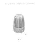
[0027] FIG. 1 depicts the registered cap, whose vertical ribs 2 are provided with a rubber cover 9.
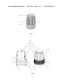
[0028] FIG. 2 depicts a cap according to application RU 2008145117, a longitudinal section and front view of the cap.
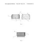
[0029] FIG. 3 depicts a front view of a common cap and its longitudinal section.
[0030] FIG. 4 depicts a common cap, a side wall 4 of which is provided with a rubber cover 9.
[0031] FIG. 5 depicts an isometric view of the registered cap having an enlarged upper chamber and vertical stiffener ribs and an isometric view of a rubber cover.
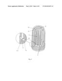
[0032] FIG. 6 depicts an isometric view of the registered cap having a rubber cover 9 arranged on the walls of vertical stiffener ribs 2.
[0033] FIG. 7 depicts an isometric view of the registered cap having a connecting rubber circle 18 fully filled with a rubber cover 22.
[0034] FIG. 8 depicts a longitudinal section view of the cap under pressure having an enlarged upper chamber 1 and vertical stiffener ribs 2 and of the cap having an enlarged upper chamber 1 without vertical stiffener ribs.
[0035] FIG. 9 depicts an isometric view of the registered cap provided with a hook 5.
[0036] FIG. 10 depicts a longitudinal section of a common cap and an enlarged isometric view of the top 20 of the cap on which the stiffener rib is standing on the registered cap.
[0037] FIG. 11 depicts an isometric view of a rubber cover 9 which extends along 24 the lower side wall 4 at a place where small ribs 3 are provided for the convenience of loosening FIG. 11.
[0038] FIG. 12 depicts in isometric view a hook in top view and a top view on a <<stiffener rib for reinforcing the hook>> 25.
[0039] FIG. 13 depicts an isometric view of a hook in bottom view and a bottom view on a <<stiffener rib for reinforcing the hook>> 25.
[0040] FIG. 14 depicts an isometric view of a hook, longitudinal section and front view on a <<stiffener rib for reinforcing the hook>> 25.
[0041] In the method for reducing slippage which is performed on a common standard cap FIG. 2, the desired result is achieved due to the fact that a rough cover is provided on the lower side wall 4 of the cap which comprises on its inner side a threaded portion 8 of the cap FIG. 3, 10.
[0042] While in the filed method for reducing slippage, a rough cover is not only provided on the lower side wall 4, but also on the vertical stiffener rib 2 which is provided between the top 20 of the cap and the surface 21 of the enlarged upper chamber 1 and which is also standing on the top 20 of the cap and which abuts to the side wall 7 of the enlarged chamber 1.
[0043] When providing on the vertical stiffener rib 2 a resin cover 9 FIG. 6 and making said construction element less slick or smooth, the vertical stiffener rib 2 itself continues performing the function of reinforcing the wall 7 of the enlarged upper chamber 1 FIG. 2, thus it is considerably larger and heavier than, for example, the small rib 3 which suits only for reducing slippage on the lower side wall 4 of a common cap FIG. 3.
[0044] Therefore, the vertical stiffener rib 2 having applied on its surface a rubber cover 9, continues to be capable of providing a deformation restraint to side wall 7 FIG. 8 of enlarged upper chamber 1, which may arise at an excessive inner pressure of a carbonized beverage.
[0045] The distinctive feature of the registered method is that the external wall 12 of stiffener rib 2 FIG. 5, on which there is a porous rubber cover 9 applied, has an indentation portion 10 from the edge of the top 20 of the cap which is fillable with rubber cover, in contrast to the adjacent 11 stiffener rib on which there is no disposition of rubber cover provided FIG. 5.
[0046] Cast or mold of the rubber cover is performed by the following method, wherein a forming element of the mold rises or stands in a free or cleared area or region of the indentation 10 located opposite the external wall 12 of the vertical stiffener rib 2 FIG. 5, and then the butt or end 9.1 of the rubber cover 9 is molded FIG. 6, and further molding occurs on the outer surface of the wall 12 of the vertical stiffener rib 2 FIG. 6 to connecting node 19 which adjoins connecting rubber circle 18, and then passes through the connecting rubber circle 18 into the subsequent connecting node 19, and then on the surface of the vertical stiffener rib scheduled for applying the resin cover. Thus the connecting rubber circle 18 and the connecting node 19 combine all vertical stiffener ribs scheduled for having a resin cover applied thereon.
[0047] This is done so that, when molding the rubber surface, injection of melted rubber into the forming plate occurs through one nozzle, that is, through a single rubber injection point, and thus, so that all ducts of the forming plate are filled and all rubber surfaces on vertical stiffener ribs which stand separately from each other are formed. Hence, the rubber circle 18 fulfills the role of a central duct through which a distribution of rubber flow on all external walls 12 of vertical stiffener ribs 2 takes place at the moment of injection FIG. 5. What is more, the rubber circle 18 may be formed fully filled 22 with rubber FIG. 7. Hence, it may have the form of a ball 17 FIG. 9, which increases the aesthetic perception of the cap.
[0048] The given method differs from, for example, the method of applying a rubber cover to a common cap FIG. 4, in that, that on the common cap the connecting rubber circle 18 lies on the top 20 of the cap, at a location at which its ribs 8 are provided FIG. 10, while at the cap having an enlarged upper chamber 1 on the top 20 of the cap, at its edges there stand vertical stiffener ribs 2 so that it is not possible to arrange the connecting circle 18 there and thus it has a newly arranged location at the side of the top 20 of the cap, on the surface 21 of the enlarged upper chamber 1.
[0049] Application of the indentation portion 10 in the give method allows obtaining yet one benefit which is the equal arrangement of the rubber end or butt 9.1 from the end of the top 20 of the cap and a butt or end 15 which does not comprise a rubber cover FIG. 6, 7. Because of this all vertical stiffener ribs 2 both those which have a rubber cover and those without rubber cover stand with their ends or butts exactly equally on the end of the top 20 of the cap, which allows the flat of a hand to uniformly grip the upper part of the cap, both produced with and produced without rubber cover construction elements.
[0050] Using the method with indentation portion 10, we provide deposition of the rubber cover on necessary portions of the enlarged cap of RU 2008145117 and thus preserve its initial size so that one will not have to reconfigure existing machines for sealing caps according to application RU 2008145117 or, for example, to produce new head windings for them, but rather, said method gives a possibility of leaving existing machines for winding in the original form without changes in the production, and using the same cap winding heads which already wind caps according to application RU 2008145117 not having a rubber cover.
[0051] The used method of applying a rubber cover on vertical stiffener ribs allows depositing it also in the case if on the enlarged upper chamber there will be fixed an additional construction element, for example one like the hook 5 FIG. 9, wherein the hook may have on its surface 16 an inscription. Furthermore, the rubber cover 9 may be also applied on a vertical stiffener rib which is provided inside the hook 23. Herewith, the inner surface of the hook may be complex, it may, for example, have on its inner surface a <<stiffener rib for reinforcing the hook>> 25 FIG. 12, 13, 14, 15.
[0052] The given invention allows improving characteristics or features of the cap according to application RU 2008145117 and at the same time saving the unification of screw-on equipment, which allows economizing resources when implementing the improved cap into products.
[0053] The materiel used to produce the cap for PET-bottles with the method of extrusion under pressure is polyethylene or propylene.
[0054] The materiel used to produce the rubber cover is liquid rubber or resin which is supplied in a heated form and under great pressure to the surface of plastic parts, after which it is immediately hardened on them while preserving their given form. Thus, for example, the resin cover changes during the manufacture of plastic toothbrush handles, on which rubber insertions are applied for reducing slip of the handle when using the brush.
[0055] The given production technology of plastic products with the use of rubber-coated inserts is the most widespread in the industry. The method of manufacturing plastic parts and rubber-coated inserts is called two-component molding, where first a plastic part is molded, noticeably leaves one forming plate and in its place rises another forming plate of the mold with recesses under rubber elements, and then after clamping the mold heated rubber is injected under high pressure which hits on the surface of the plastic part and hardens instantly taking the desired shape.
[0056] Thus, the registered cap construction having an enlarged upper chamber and rubber cover applied on its vertical stiffener ribs allows improving its loosening when being operated at any weather condition and provides the required conditions of modern comfort while using it, and at the same time preserves the unification of spin-on equipment in manufacturing.
User Contributions:
Comment about this patent or add new information about this topic:
Images included with this patent application:
 |  |
 |  |
 |  |
| Similar patent applications: | |
| Date | Title |
|---|---|
| 2012-06-28 | Method and apparatus for beverage bottle |
| 2012-01-26 | Baby feeding bottle |
| 2012-06-28 | Healthy pour serving size cap |
| 2013-02-28 | Venting baby bottle |
| 2013-12-12 | Silicone baby bottle |
| New patent applications in this class: | |
| Date | Title |
|---|---|
| 2019-05-16 | Bottle cap and fitment assembly and method |
| 2016-05-19 | Crown cap |
| 2016-04-28 | Plastic bottles for perfume compositions having improved crazing resistance |
| 2016-04-28 | Non-porous weights for use in fermenting vessels |
| 2016-02-18 | Vented cap assembly |
| Top Inventors for class "Bottles and jars" | |
| Rank | Inventor's name |
|---|---|
| 1 | Takao Iizuka |
| 2 | Sheldon E. Yourist |
| 3 | Justin A. Howell |
| 4 | Justin C. Yarro |
| 5 | Michel Boukobza |