Patent application title: Uplink Power Control
Inventors:
Honghai Zhang (Seattle, WA, US)
Honghai Zhang (Seattle, WA, US)
Narayan Prasad (Wyncote, PA, US)
Narayan Prasad (Wyncote, PA, US)
Sampath Rangarajan (Bridgewater, NJ, US)
Assignees:
NEC Laboratories America, Inc.
IPC8 Class: AH04W5214FI
USPC Class:
455522
Class name: Central station (e.g., master, etc.) to or from mobile station transmission power control technique
Publication date: 2014-03-27
Patent application number: 20140087783
Abstract:
A method for uplink power control implemented in a wireless
communications system including one or more user equipment, a serving
base station, and at least one neighboring base station is disclosed. The
method comprises measuring, at each user equipment, pathloss, sending,
from each user equipment to the serving base station, the pathloss, and
determining, at the serving base station, uplink transmit power based on
the pathloss. Other methods, systems, and apparatuses also are disclosed.Claims:
1. A method for uplink power control implemented in a wireless
communications system including one or more user equipments, a serving
base station, and at least one neighboring base station, the method
comprising: measuring, at each user equipment, pathloss; sending, from
each user equipment to the serving base station, the pathloss; and
determining, at the serving base station, uplink transmit power based on
the pathloss.
2. The method as in claim 1, further comprising: measuring, at said at least one neighboring base station, interference power on a resource block sent to the serving base station; computing, at the serving base station, an average interference power for each user equipment; determining, at the serving base station, a neighboring base station most strongly interfered by each user equipment; and setting, at the serving base station, a power adjustment based on a target interference power and an average maximum interference power.
3. The method as in claim 2, wherein the pathloss comprises downlink pathloss.
4. The method as in claim 3, wherein the downlink pathloss comprises pathloss PLDLi from the serving base station and PLDL,i.sup.strNB from the most strongly interfered neighboring base station.
5. The method as in claim 1, wherein the determination comprises: determining per-RB transmit power (transmit PSD).
6. The method as in claim 5, wherein the transmit PSD comprises PSDi=min(PSDmax,P0+αPLDL,i+δmax,.GAM- MA.0+PLDL,i.sup.strNB), where PSDmax is maximum transmit PSD, P0 is desired receiving power, α is a fraction of pathloss compensation, δmax is a maximum power increase over fractional power control (FPC), and Γ0 is target interference power.
7. A method for uplink power control implemented in a serving base station used in a wireless communications system including one or more user equipments and at least one neighboring base station, the method comprising: receiving, from each user equipment, pathloss; and determining uplink transmit power based on the pathloss, wherein each user equipment measures the pathloss.
8. The method as in claim 7, further comprising: computing an average interference power for each user equipment; determining a neighboring base station most strongly interfered by each user equipment; and setting a power adjustment based on a target interference power and an average maximum interference power, wherein said at least one neighboring base station measures interference power on a resource block sent to the serving base station;
9. The method as in claim 8, wherein the pathloss comprises downlink pathloss.
10. The method as in claim 9, wherein the downlink pathloss comprises pathloss PLDLi from the serving base station and PLDL,i.sup.strNB from the most strongly interfered neighboring base station.
11. The method as in claim 7, wherein the determination comprises: determining per-RB transmit power (transmit PSD).
12. The method as in claim 11, wherein the transmit PSD comprises PSDi=min(PSDmax,P0+αPLDL,i+δmax,.GAM- MA.0+PLDL,i.sup.strNB), where PSDmax is maximum transmit PSD, P0 is desired receiving power, α is a fraction of pathloss compensation, δmax is a maximum power increase over fractional power control (FPC), and Γ0 is target interference power.
13. A method for uplink power control implemented in a user equipment used in a wireless communications system including a serving base station and at least one neighboring base station, the method comprising: measuring pathloss; and sending to the serving base station the pathloss, wherein the serving base station determines uplink transmit power based on the pathloss.
14. The method as in claim 13, wherein said at least one neighboring base station measures interference power on a resource block sent to the serving base station, wherein the serving base station computes an average interference power for each user equipment, wherein the serving base station determines a neighboring base station most strongly interfered by each user equipment, and wherein the serving base station sets a power adjustment based on a target interference power and an average maximum interference power.
15. The method as in claim 14, wherein the pathloss comprises downlink pathloss.
16. The method as in claim 15, wherein the downlink pathloss comprises pathloss PLDLi from the serving base station and PLDL,i.sup.strNB from the most strongly interfered neighboring base station.
17. The method as in claim 13, wherein the determination comprises: determining per-RB transmit power (transmit PSD).
18. The method as in claim 17, wherein the transmit PSD comprises PSDi=min(PSDmax,P0+αPLDL,i+δmax,.GAM- MA.0+PLDL,i.sup.strNB), where PSDmax is maximum transmit PSD, P0 is desired receiving power, α is a fraction of pathloss compensation, δmax is a maximum power increase over fractional power control (FPC), and Γ0 is target interference power.
Description:
RELATED APPLICATION INFORMATION
[0001] This application is a divisional of co-pending patent application Ser. No. 13/617,766, filed Sep. 14, 2012, which in turn claims priority to provisional application No. 61/535,636, filed Sep. 16, 2011, the contents of both of which are incorporated herein by reference
BACKGROUND OF THE INVENTION
[0002] The present invention relates generally to wireless communications, and more particularly, to long term evolution LTE and long term evolution advanced LTE-A uplink UL power control.
[0003] In LTE and LTE-Advanced systems, uplink power control is crucial to reduce the interference and improve system throughput. 3GPP has defined fractional power control (FPC) to control the uplink transmission power. The major issue is that the interference created at neighboring cells highly depends on the users scheduled in the present cell. As a result, signal-to-interference-noise-ration SINR estimation, user scheduling, and modulation and coding scheme MCS selection become challenging in neighboring cells.
[0004] There has been a proposal to compensate the transmit power by a fraction of the difference between the pathloss to the serving cell and that to the second strongest cell. Another technique proposed to continuously adjust the transmission power to maintain a target total interference power a user creates to the entire system. However, the individual interference a user creates to a given neighboring cell may still be highly variable and heavily dependent on the user that is scheduled in the present cell.
[0005] Accordingly, there is a need for improved LTE and LTE-A uplink power control.
BRIEF SUMMARY OF THE INVENTION
[0006] The present invention is directed to a method for long term evolution LTE uplink power control for communications between a plurality of both eNodeB and user equipment UE, the method includes measuring by user equipment UE downlink pathloss which is sent to an eNodeB that determines uplink UL transmit power based on the downlink pathloss, under an open loop power control that is selected; and measuring by a neighboring eNodeB interference power on each resource block that is sent to a serving eNodeB, the serving eNodeB computing an average interference power for each scheduled user and determines a most strongly interfered neighbor eNodeB by each UE, setting a power adjustment based on a target interference and an average maximum interference power, updating the power adjustment if a UE is not sufficiently scheduled and setting an uplink transmit power, under a closed loop power control that is selected.
[0007] These and other advantages of the invention will be apparent to those of ordinary skill in the art by reference to the following detailed description and the accompanying drawings.
BRIEF DESCRIPTION OF THE DRAWINGS
[0008] FIG. 1A shows the uplink power control for LTE and LTE-A, in accordance with the invention;
[0009] FIG. 2A is a block diagram of the open loop aspect shown in FIG. 1A, in accordance with the invention;
[0010] FIG. 3A is a block diagram of the closed loop aspect shown in FIG. 1A, in accordance with the invention; and
[0011] FIG. 4A is a block diagram of the steps of the uplink power control for LTE and LTE-A, in accordance with the invention.
DETAILED DESCRIPTION
[0012] The present invention is directed to uplink power control for LTE and LTE-A that includes open-loop and closed-loop power control aspects to simultaneously bring down the average and the variance of the interference power in neighboring cells. Reducing the average interference increases the signal-to-noise-interference-ratio SINR values in neighboring cells. Also reducing the variance of the interference enables more accurate estimation of SINR values and the modulation and coding scheme MCS selection. Together they improve the system throughput significantly.
[0013] The inventive uplink power control for LTE and LTE-A obtains a 7-8% average user throughput improvement without sacrificing cell-edge user throughput in a network with low penetration loss and they obtain 4-6% gain on the average user throughput and 15-23% gain on the cell-edge throughput, all compared to the 3GPP FPC scheme.
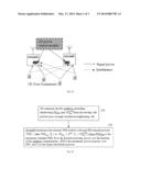
[0014] Referring to FIG. 1A, there is shown an exemplary diagram of the inventive uplink power control for LTE and LTE-A. An exemplary UL power control module is responsive to power signals and interferences between eNodeBs and user equipment UE units.
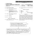
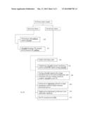
[0015] The inventive uplink power control includes open loop steps, shown in block diagrams of FIGS. 2A and 4A. The user equipment UE estimates downlink DL pathloss (including shadowing) PLDL,i and PLDL,i.sup.strNB from the serving cell and the most strongly interfered neighboring cell, respectively 110. The eNodeB determines the transmit PSD (which is the per-RB transmit power):
PSDi=min(PSDmax,P0+αPLDL,i+δmax,.GA- MMA.0+PLDL,i.sup.strNB),
[0016] where PSDmax is the maximum transmit PSD, P0 is the desired receiving power, α is the fraction of the pathloss compensation, δmax is the maximum power increase over FPC, and Γ0 is the target interference power 120.
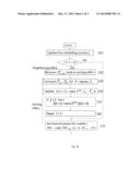
[0017] The inventive uplink power control includes closed loop steps, shown in FIG. 3A. Initially, a scheduling count fi is updated 210, and then a neighboring eNodeB measures interference power on each resource block RB, and sends it to the serving eNodeB 220 (e.g., measure Ps→bc, send to serving eNBs). A serving eNodeB computes the average interference power for each scheduled user, and determines the most strongly interfered neighbor eNodeB by each UE 230 (e.g, compute {tilde over (P)}i,b, Pi,b, let {circumflex over (b)}=argmaxb Pi,b). Then there is a setting of the power adjustment δi based on target interference and the average maximum interference power 240 (e.g, update δi (t+1)=min(δmax, Γ0- Pi,{circumflex over (b)}). The power adjustment δi is updated if the user is not sufficiently scheduled 250 (e.g., if fi<f then δi (t+1)=min (δmax, δi(t)+Δ). Reset fi=0 260. Lastly, the uplink transmit power PSDi is set 270 (e.g., set transmit power for mobile i: PSDi=min(PSDmax, P0+αPLDL,i+δi)).
[0018] This patent application also discloses the following subject matter:
[0019] 1. A method for long term evolution LTE uplink power control for communications between a plurality of both eNodeB and user equipment UE, said method comprising the steps of:
[0020] measuring by user equipment UE downlink pathloss which is sent to an eNodeB that determines uplink UL transmit power based on the downlink pathloss, under an open loop power control that is selected; and
[0021] measuring by a neighboring eNodeB interference power on each resource block that is sent to a serving eNodeB, the serving eNodeB computing an average interference power for each scheduled user and determines a most strongly interfered neighbor eNodeB by each UE, setting a power adjustment based on a target interference and an average maximum interference power, updating the power adjustment if a UE is not sufficiently scheduled and setting an uplink transmit power, under a closed loop power control that is selected.
[0022] 2. The method of above item 1, wherein said downlink pathloss includes pathloss PLDLi and PLDL,i.sup.strNB from the serving cell and the most strongly interfered neighboring cell, respectively.
[0023] 3. The method of above item 1, wherein the eNodeB determining uplink UL transmit power based on the downlink pathloss includes determining the transmit PSD, which is the per-RB transmit power.
[0024] 4. The method of above item 3, wherein the transmit PSD comprises PSDi=min(PSDmax,P0+αPLDL,i+δmax,.GAM- MA.0+PLDL,i.sup.strNB) where PSDmax is the maximum transmit PSD, P0 is the desired receiving power, α is the fraction of the pathloss compensation, δmax is the maximum power increase over FPC, and Γ0 is the target interference power.
[0025] The foregoing is to be understood as being in every respect illustrative and exemplary, but not restrictive, and the scope of the invention disclosed herein is not to be determined from the Detailed Description, but rather from the claims as interpreted according to the full breadth permitted by the patent laws. Additional information is provided in Appendix A to the application. It is to be understood that the embodiments shown and described herein are only illustrative of the principles of the present invention and that those skilled in the art may implement various modifications without departing from the scope and spirit of the invention. Those skilled in the art could implement various other feature combinations without departing from the scope and spirit of the invention.
User Contributions:
Comment about this patent or add new information about this topic:
Images included with this patent application:
 |  |
 |  |
| Similar patent applications: | |
| Date | Title |
|---|---|
| 2012-06-21 | Uplink power control |
| 2012-11-08 | Uplink power control |
| 2013-09-12 | Uplink power control scheme |
| 2014-02-20 | Method and system for self-optimized uplink power control |
| 2010-12-23 | Method and apparatus for forward link power control |
| New patent applications from these inventors: | |
| Date | Title |
|---|---|
| 2022-03-31 | Unmanned aerial vehicle network |
| 2021-10-07 | Rfid-based self-checkout systems using cycle counting |
| 2021-10-07 | Near real-time reconstruction using drones |
| 2020-09-17 | Tracking rfid groups with spatio-temporal proximity |
| 2020-09-17 | Tracking indoor objects with inertial sensor measurements |
| Top Inventors for class "Telecommunications" | |
| Rank | Inventor's name |
|---|---|
| 1 | Ahmadreza (reza) Rofougaran |
| 2 | Jeyhan Karaoguz |
| 3 | Ahmadreza Rofougaran |
| 4 | Mehmet Yavuz |
| 5 | Maryam Rofougaran |