Patent application title: TRANSMISSION LINE SYSTEM
Inventors:
Shao-Wei Wang (New Taipei, TW)
Assignees:
HON HAI PRECISION INDUSTRY CO., LTD.
IPC8 Class: AH01P308FI
USPC Class:
333 1
Class name: Wave transmission lines and networks plural channel systems
Publication date: 2014-03-27
Patent application number: 20140085018
Abstract:
An exemplary transmission line system is provided. The system includes a
first transmission line partially arranged on a first layer of a PCB
including first structure units and partially arranged on a third layer
of the PCB including second structure units, and a second transmission
line arranged on a second layer of the PCB. Each first structure unit and
each second structure respectively include a first connection line, a
second connection line, and a first curved line; and a third connection
line, a fourth connection line, and a second curved line. A second end of
the first connection line and the second connection line of each of the
first structure units are respectively connected to a second end of the
third connection line and the fourth connection line of the adjacent
second structure unit through vias.Claims:
1. A transmission line system arranged on a PCB which comprises a first
layer, a second layer, and a third layer in sequence, the transmission
line system comprising: a first transmission line configured to transmit
a first signal from a signal source to a signal destination; one part of
the first transmission line being arranged on the first layer of the PCB,
other part of the first transmission line being arranged on the third
layer of the PCB; the part of the first transmission line arranged on the
first layer of the PCB comprising a plurality of first structure units,
each of the plurality of first structure units comprising a first
connection line, a second connection line, and a first curved line, each
of the first connection lines and each of the second connection lines
being straight lines, each of the first curved lines being curved line,
the first curved line first end being connected to the first connection
line first end, and the first curved line second end being connected to
the second connection line first end; the other part of the first
transmission line, arranged on the third layer of the PCB, comprising a
plurality of second structure units; each of the plurality of second
structure units comprising a third connection line, a fourth connection
line, and a second curved line; each of the third connection line and the
fourth connection line being straight lines, each of the second curved
lines being curved line, the second curved line first end being connected
to the third connection line first end, and the second curved line second
end being connected to the fourth connection line first end; the first
connection line second end of each of the plurality of first structure
units being connected to the third connection line second end of the
adjacent second structure unit through a via, and the second connection
line second end of each of the plurality of first structure units being
connected to the fourth connection line second end of the adjacent second
structure unit through another via; and a second transmission line
configured to transmit a second signal from the signal source to the
signal destination; and the second transmission line being a straight
line arranged on the second layer of the PCB; wherein the first signal
and the second signal cooperatively form a differential-mode signal, the
first signal and the ground, and the second signal and the ground
cooperatively form a common-mode signal.
2. The transmission line system as described in claim 1, wherein the first structure units and the second structure units are alternately arranged and are connected from beginning to end in series through the vias to form the first transmission line.
3. The transmission line system as described in claim 2, wherein the first transmission line surrounds the second transmission line.
4. The transmission line system as described in claim 1, wherein the length of each of the first connection lines is the same as the length of each of the fourth connection lines, and the length of each of the second connection lines is the same as the length of each of the third connection lines.
5. The transmission line system as described in claim 4, wherein each of the first curved lines and each of the second curved lines are "L-shaped"; and when the arrangement of each of the first curved lines is rotated about 90 degree anticlockwise, the arrangement of each of the second curved lines is parallel to the arrangement of each of the rotated first curved lines.
6. The transmission line system as described in claim 5, wherein a projection of the first transmission line on a plane parallel with the PCB is a square wave.
Description:
BACKGROUND
[0001] 1. Technical Field
[0002] The present disclosure relates to transmission line systems and, more particularly, to a transmission line system capable of simultaneously transmitting a common signal in a frequency and a differential signal in another frequency.
[0003] 2. Description of Related Art
[0004] A known transmission line system can simultaneously transmit a common-mode signal and a differential-mode signal in the same frequency. However, the same frequency of the common-mode signal and the differential-mode signal cannot be used together. Thus, when the common-mode signal or the differential-mode signal is needed to be used, another electronic component is employed to filter the unneeded differential-mode signal or the unneeded common-mode signal, which increases the cost of transmitting the signal. Therefore, it is desired to provide a transmission line system to resolve the above problem.
BRIEF DESCRIPTION OF THE DRAWINGS
[0005] The components in the drawings are not necessarily drawn to scale, the emphasis instead being placed upon clearly illustrating the principles of the transmission line system. Moreover, in the drawings, like reference numerals designate corresponding parts throughout the several views.
[0006] FIG. 1 is a schematic view of a transmission line system, in accordance with an exemplary embodiment.
[0007] FIG. 2 is a schematic view showing the transmission line system of the FIG. 1 arranged on a printed circuit board (PCB), in accordance with an exemplary embodiment.
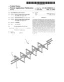
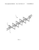
[0008] FIG. 3 is a schematic view of a first transmission line of the transmission line system of the FIG. 1, in accordance with an exemplary embodiment.
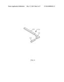
[0009] FIG. 4 is a partial, enlarged, exploded view of the circled portion IV of FIG. 3.
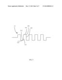
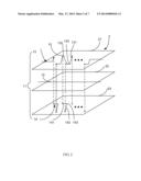
[0010] FIG. 5 is an illustrating view showing the projection of the first transmission line of the FIG. 3 on a plane parallel to the PCB of FIG. 2, in accordance with an exemplary embodiment.
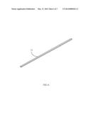
[0011] FIG. 6 is a schematic view of a second transmission line of the transmission line system of the FIG. 1, in accordance with an exemplary embodiment.
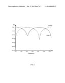
[0012] FIG. 7 is an illustrating view showing the transmission of the common signal and the differential signal in the transmission line system of FIG. 1, in accordance with an exemplary embodiment.
DETAILED DESCRIPTION
[0013] The disclosure is illustrated by way of example and not by way of limitation in the figures of the accompanying drawings in which like references indicate similar elements. It should be noted that references to "an" or "one" embodiment in this disclosure are not necessarily to the same embodiment, and such references mean "at least one".
[0014] FIGS. 1-2 show a transmission line system 1 of the embodiment. The transmission line system 1 is arranged on a printed circuit board (PCB) 2. The PCB 2 includes a first layer 21, a second layer 22, and a third layer 23 in sequence. The transmission line system 1 includes a first transmission line 11 and a second transmission line 12. One part of the first transmission line 11 is arranged on the first layer 21. Other part of the first transmission line 11 is arranged on the third layer 23. The part of the first transmission line 11 arranged on the first layer 21 and the other part of the first transmission line 11 arranged on the third layer 23 are alternately arranged and are connected from beginning to end in series to form the first transmission line 11. The second transmission line 12 is arranged on the second layer 22. The first transmission line 11 transmits a first signal from a signal source to a signal destination. The second transmission line 12 transmits a second signal from the signal source to the signal destination. The first signal and the second signal cooperatively form a differential-mode signal. The first signal and the ground, and the second signal and the ground cooperatively form a common-mode signal.
[0015] FIGS. 3-4 show the part of the first transmission line 11 arranged on the first layer 21 including a number of first structure units 13. Each first structure unit 13 includes a first connection line 131, a second connection line 132, and a first curved line 133. The first connection line 131 and the second connection line 132 are straight lines. The first curved line 133 is a curved line. The first curved line 133 first end is connected to the first connection line 131 first end, and the first curved line 133 second end is connected to the second connection line 132 first end. The other part of the first transmission line 11 arranged on the third layer 23 includes a number of second structure units 14. Each second structure unit 14 includes a third connection line 141, a fourth connection line 142, and a second curved line 143. The third connection line 141 and the fourth connection line 142 are straight lines, and the second curved line 143 is a curved line. The second curved line 143 first end is connected to the third connection line 141 first end, and the second curved line 143 second end is connected to the fourth connection line 142 first end.
[0016] A number of vias 15 extend through the second layer 22 of the PCB 2. The first connection line 131 second end of each first structure unit 13 is connected to the third connection line 141 second end, of the adjacent second structure unit 14, through the via 15. The second connection line 132 second end of each first structure unit 13 is connected to the fourth connection line 142 second end, of the adjacent second structure unit 14, through the via 15. Thus, the first structure unit 13 arranged on the first layer 21 and the second structure unit 14 arranged on the third layer 23 are connected from beginning to end in series through the vias 15 to form the first transmission line 11 (see FIG. 3). In this way, the first transmission line 11 is arranged to surround the second transmission line 12. In the embodiment, the second transmission line 12 is a straight line (see FIG. 6).
[0017] In the embodiment, the length of each third connection line 141 is the same as the length of each second connection line 132, and the length of each fourth connection line 142 is the same as the length of each first connection line 131. Each first curved line 133 and each second curved line 143 are L-shaped, thus each first structure unit 13 and each second structure unit 14 are "L-shaped". When the arrangement of each first curved line 133 is rotated about 90 degree anticlockwise, the arrangement of each second curved line 143 is parallel to the arrangement of each rotated first curved line 133. The vias 15 perpendicularly extend through the second layer 22 of the PCB 2.
[0018] FIG. 5 shows that the projection point of the second end of the first connection line 131 of each first structure unit 13 on a plane parallel to the PCB 2 is the same point as the projection point of the second end of the third connection line 141 of the adjacent second structure unit 14 on the plane parallel to the PCB 2. And the projection point of the second end of the second connection line 132 of each first structure unit 13 on the plane parallel to the PCB 2 is the same point as the projection point of the second end of the fourth connection line 142 of the adjacent second structure unit 14 on the plane parallel to the PCB 2. Thus, the projection of the first transmission line 11 on the plane parallel to the PCB 2 is a square wave.
[0019] FIG. 7 is an illustrating view showing the common-mode signal and the differential-mode signal transmitting in the transmission line system 1. The transverse axis of the illustrating view represents the frequency. The longitudinal axis of the illustrating view represents the intensity of the signal. Line `a` in the illustrating view shows the differential-mode signal transmitted in the transmission line system 1. Line `b` in the illustrating view shows the common-mode signal transmitted in the transmission line system 1. When the intensity of the common-mode signal or the differential-mode signal in a frequency is less than -10 db, the common-mode signal or the differential-mode signal in the frequency can pass through the transmission line system 1; otherwise, the common-mode signal or the differential-mode signal in the frequency cannot pass through the transmission line system 1. In FIG. 7, the common-mode signal or the differential-mode signal in the same frequency can pass through the transmission line system 1, and the common-mode signal and the differential-mode signal in the different frequency can simultaneously pass through the transmission line system 1. With this configuration, the transmission line system 1 can transmit the common-mode signal or the differential-mode signal and can also simultaneously transmit the common-mode signal and the differential-mode signal in the different frequency. In this way, another electronic component which is configured to filter the unneeded differential-mode signal or the unneeded common-mode signal is not needed.
[0020] In one embodiment, the length of the first connection line 131, the fourth connection line 142, the second connection line 132, and the third connection line 141, or the length of the first connection line 131 and the fourth connection line 142, or the length of the second connection line 132 and the third connection line 141 can be varied to change the intensity of the common-mode signal and the differential-mode signal in each frequency.
[0021] Although the current disclosure has been specifically described on the basis of the exemplary embodiment thereof, the disclosure is not to be construed as being limited thereto. Various changes or modifications may be made to the embodiment without departing from the scope and spirit of the disclosure.
User Contributions:
Comment about this patent or add new information about this topic:
Images included with this patent application:
 |  |
 |  |
 |  |
 |  |
| Similar patent applications: | |
| Date | Title |
|---|---|
| 2014-10-02 | High-frequency transmission line and electronic device |
| 2014-10-02 | High-frequency transmission line and electronic device |
| 2014-10-30 | Transmission line driver with output swing control |
| 2014-09-25 | Waveguide circulator with improved transition to other transmission line media |
| 2014-10-23 | Signal transmission cable and flexible printed board |
| New patent applications in this class: | |
| Date | Title |
|---|---|
| 2018-01-25 | Waveguide structures |
| 2016-12-29 | Transmission line design and method of forming the same |
| 2016-07-14 | 3d multilayer high frequency signal line |
| 2016-06-30 | Ic-package interconnect for millimeter wave systems |
| 2016-06-02 | Active quasi circulator |
| Top Inventors for class "Wave transmission lines and networks" | |
| Rank | Inventor's name |
|---|---|
| 1 | Hiroyuki Nakamura |
| 2 | Noboru Kato |
| 3 | Tetsuya Tsurunari |
| 4 | Dariusz Burak |
| 5 | Ahmadreza Rofougaran |