Patent application title: MOP HEAD RETAINER
Inventors:
Silvio Digiammarino (Concord Ontario, CA)
IPC8 Class: AA47L1346FI
USPC Class:
15150
Class name: Implements holder, mop pivoted jaw
Publication date: 2014-03-27
Patent application number: 20140082870
Abstract:
An improved retainer for a mop head is disclosed. The retainer is of the
type having a body and an elongate jaw, the jaw being movable between a
use position and a release position. In the use position, the jaw is
orientated substantially parallel to the body and, in use, captures the
mop head against the body. In the release position, the jaw extends away
from the body to permit removal and replacement of the mop head. The
improvement comprises a foot pad operatively coupled to the body such
that application of force to the foot pad causes deformation of the body
to release the jaw for movement.Claims:
1. An improved retainer for a mop head, the retainer being of the type
defining the terminus of a mop handle in use having an elongate body that
has first and second ends and a use configuration wherein the body
extends substantially perpendicular to the mop handle in use a first,
protuberance adjacent the first end of the body and a second protuberance
adjacent the second end of the body, the protuberances each extending
from the elongate body such that, in use, the protuberances and the mop
handle extend in opposite directions an elongate jaw one end of said jaw
being pivotably secured to the terminus of the first protuberance, to
provide for movement of the jaw between a use position whereat the jaw is
orientated substantially parallel to the body and, in use, captures the
mop head against the body and a release position, whereat the jaw extends
away from the body to permit removal and replacement of the mop head
wherein the second end of the body is resiliently deformable to a release
configuration; and the other end of the jaw and the second protuberance
are adapted such that when the body is in the use configuration and the
jaw is moved from the release position to the use position, the second
protuberance deforms to permit movement of the jaw to the use position
and thereafter reforms to capture the jaw in the use position when the
jaw is in the use position and the body is in the use configuration,
deformation of the second end of the body to the release configuration
separates the second protuberance from the other end of the jaw to permit
movement of the jaw to the release position wherein the improvement
comprises a foot pad operatively coupled to the second end of the body
such that application of force to the foot pad in the direction of
protuberance extension causes deformation of the body to the release
configuration and removal of force from the foot pad causes reformation
of the body in the use configuration.
2. A retainer according to claim 1, further comprising an elongate shank part that connects the mop handle to the body in use.
3. A retainer according to claim 2, further comprising a lug adjacent the second end of the body and orientated such that the lug and the second protuberance extend in opposite directions; and a strut to which the lug extends and itself extending from the lug to the shank, the strut carrying the fad peg and being resiliently deformable such that said application of force to the foot pad draws the end of the lug towards the shank and causes the deformation of the body to the release configuration, thereby to provide for said operatively coupling of the foot peg to the second end of the body.
4. A retainer according to claim 1, further comprising a mop hook extending from the jaw beyond the end of the second post.
Description:
CROSS-REFERENCE TO RELATED APPLICATIONS
[0001] This Application claims the benefit of U.S. Provisional Application No. 61/706,161, filed Sep. 27, 2012, which is hereby incorporated by reference herein in its entirety.
FIELD OF THE INVENTION
[0002] This invention relates to the field of sanitation.
BACKGROUND OF THE INVENTION
[0003] Mops are well known, and it is commonplace for mops to permit the removal and replacement of worn or soiled mop heads.
[0004] A common arrangement involves a body secured to the mop handle and a pivoting jaw to retain and releasable grip the mop head.
[0005] However, known arrangements of this type suffer from one or more of the following:
[0006] relatively high cost
[0007] relatively poor durability
[0008] propensity for unintentional disengagement
[0009] difficult to disengage, particularly when cold
[0010] propensity for unintentional contact of the mop head with the hands of the user during disengagement
SUMMARY OF THE INVENTION
[0011] An improved retainer for a mop head forms one aspect of the invention. The retainer is of the type
[0012] that
[0013] defines the terminus of a mop handle in use
[0014] has an elongate body that has first and second ends and a use configuration wherein the body extends substantially perpendicular to the mop handle in use
[0015] has a first protuberance adjacent the first end of the body and a second protuberance adjacent the second end of the body, the protuberances each extending from the elongate body such that, in use, the protuberances and the mop handle extend in opposite directions
[0016] has an elongate jaw, one end of said jaw being pivotably secured to the terminus of the first protuberance, to provide for movement of the jaw between (i) a use position whereat the jaw is orientated substantially parallel to the body and, in use, captures the mop head against the body and (ii) a release position, whereat the jaw extends away from the body to permit removal and replacement of the mop head; and
[0017] wherein
[0018] the second end of the body is deformable to a release configuration; and
[0019] the other end of the jaw and the second protuberance are adapted such that: when the body is in the use configuration and the jaw is moved from the release position to the use position, the second protuberance deforms to permit movement of the jaw to the use position and thereafter reforms to capture the jaw in the use position; and when the jaw is in the use position and the body is in the use configuration, deformation of the second end of the body to the release configuration separates the second protuberance from the other end of the jaw to permit movement of the jaw to the release position
[0020] The improvement comprises a foot pad operatively coupled to the second end of the body such that application of force to the foot peg in the direction of protuberance extension causes deformation of the body to the release configuration and removal of force from the foot peg causes reformation of the body in the use configuration.
[0021] According to another aspect of the invention, an elongate shank part can connect the mop handle to the body in use.
[0022] According to another aspect of the invention, the retainer can include, to provide for said operative coupling of the foot peg to the second end of the body: a lug adjacent the second end of the body and orientated such that the lug and the second protuberance extend in opposite directions; and a strut to which the lug extends and itself extending from the lug to the shank, the strut carrying the foot peg and being deformable such that said application of force to the foot peg draws the end of the lug towards the shank and causes the deformation of the body to the release configuration.
[0023] According to another aspect of the invention, the retainer can further comprise a mop hook extending from the jaw beyond the end of the second post.
[0024] Advantages, features and characteristics of the present invention, as well as methods of operation and functions of the related elements of the structure, and the combination of parts and economies of manufacture, will become more apparent upon consideration of the following detailed description of an exemplary embodiment of the invention and the appended claims with reference to the accompanying drawings, the latter being briefly described hereinafter.
BRIEF DESCRIPTION OF THE DRAWINGS
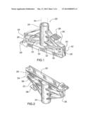
[0025] FIG. 1 is a perspective view of a mop head retainer according to an exemplary embodiment of the invention, accompanied by a phantom outline of a mop handle, the jaw portion of the retainer being shown in the use position and the body of the retainer being shown in the use configuration;
[0026] FIG. 2 is a perspective view of the structure of FIG. 1, from a different vantage point;
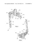
[0027] FIG. 3 is a view, similar to FIG. 1, with the jaw in the open position and the body in the use configuration;
[0028] FIG. 4 is a view of the structure of FIG. 3, from a different vantage point;
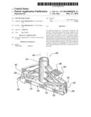
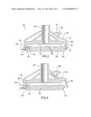
[0029] FIG. 5 is a cross-sectional view of the structure of FIG. 1
[0030] FIG. 6 is a cross-sectional view similar to FIG. 5 but showing the body in the release configuration; and
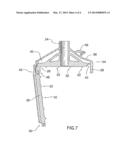
[0031] FIG. 7 is a view similar to FIG. 5, but showing the jaw in the release position.
DETAILED DESCRIPTION
[0032] Reference is now made to FIGS. 1-7 which show, as previously indicated, a mop head retainer 20 constructed according to an exemplary embodiment of the invention.
[0033] The retainer 20 will be seen to have a body 22, a shank 24, first 26 and second 28 protuberances, a jaw 30, a plurality of spikes 32, a lug 34, a strut 36, a foot pad 38 and a mop hook 39.
[0034] With reference first to the body 22, shank 24, first 26 and second 28 protuberances and jaw 30, all of the foregoing will be understood to bear similarity in function to the corresponding structures in CA2712727, which is hereby incorporated by reference herein in its entirety, in that:
[0035] the body 22 is elongate, has first 40 and second 42 ends and will be understood to have a use configuration wherein the body 22 extends substantially perpendicular to the mop handle in use. A mop handle 44 is shown in phantom outline in FIG. 1 to illustrate the relationship between the mop handle 44 and the retainer 20 in use and the position of the body 22 with reference to the phantom mop handle 44 will be understood to be representative of the use configuration
[0036] the shank 24 connects the mop handle 44 to the body 22 in use
[0037] the first protuberance 26 is adjacent the first end 40 of the body 22, the second protuberance 28 is adjacent the second end 42 of the body 22 and the protuberances 26,28 each extend from the body 22 such that, in use, the protuberances 26,28 and the mop handle 44 extend in opposite directions
[0038] the jaw 30 is elongate and has one end 46 pivotably secured to a terminus 48 of the first protuberance 26, to provide for movement of the jaw 30 between: a use position, shown in FIG. 1, whereat the jaw 30 is orientated substantially parallel to the body 22 and, in use, captures the mop head against the body 22; and a release position, shown in FIG. 3, whereat the jaw 30 extends away from the body 22 to permit removal and replacement of the mop head. The capture of the mop head against the body 22 is not shown in the present drawings but will be understood to be analogous to the capture shown in FIG. 1 of CA 2712727, which is hereby incorporated by reference herein in its
[0039] entirety. The other end 50 of the jaw 30 and the end of the second protuberance 28 engage one another when the jaw 30 is in the use position by virtue of a tab 53 on the jaw 30 and a notch 55 on the protuberance 28, these being best seen in FIG. 7
[0040] the spikes 32 extend from the jaw 30 and the body 22 such that, when the body 22 is in the use configuration, the jaw 30 is in the use position and a mop head is captured therebetween, the spikes 32 rigidly grip the mop head
[0041] the second end 42 of the body 22 is relatively thin and thus deformable to a release configuration; and the other end 50 of the jaw 30 and the second protuberance 28 are adapted such that
[0042] when the body 22 is in the use configuration and the jaw 30 is moved from the release position to the use position, the second protuberance 28 resiliently deforms to permit movement of the jaw 30 to the use position and thereafter resiliently reforms to capture the jaw 30 in the use position
[0043] when the jaw 30 is in the use position and the body 22 is in the use configuration, deformation of the second end 42 of the body 22 to the release configuration, as shown in FIG. 6, separates the second protuberance 28 from the other end 50 of the jaw 30 to permit movement of the jaw 30 to the release position
[0044] Turning now to the lug 34, strut 36 and foot pad 38:
[0045] the lug 34 is positioned adjacent the second end 42 of the body 22, extends from the body 22 and is orientated such that the lug 34 and the second protuberance 28 extend in opposite directions
[0046] the strut 36 extends from the end of the lug 34 to the shank 24 and is resiliently deformable
[0047] the foot pad 38 is carried by the strut 36 and thereby operatively coupled to the second end 42 of the body 22
[0048] The resiliently deformable nature of the strut 36 and body second end 42 is such that, in use (i) application of force to the foot pad 38 in the direction of protuberance extension A draws the end of the lug 34 toward the shank 24, as indicated by arrow B in FIG. 5, and causes deformation of the body 22 to the release configuration and (ii) removal of force from the foot pad 38 causes reformation of the body 22 in the use configuration.
[0049] Persons of ordinary skill will readily perceive that the above structure can be injection molded out of a small number of plastic components to provide a mop head that has all of the advantages of CA 2727127, namely, relatively low manufacturing costs, relatively high durability and relatively high resistance to unintentional disengagement, and at the same time, is also relatively easy to disengage by persons of moderate arm strength, minimizes the propensity for unintentional contact of the mop head with the hands of the user during disengagement
[0050] The mop hook 39, which extends from the jaw 30 beyond the second protuberance 28, provides yet further advantage associated with the issue of unintentional contact of the mop head with the hands of the user. Herein, it will be appreciated that, after the user has disengaged the mop head, a typical outcome will be a soiled and wet mop head on the floor. The mop hook 39 allows the user to, on a no-hand-contact-with-mop-head basis, easily grasp the soiled mop head and place same, for example, in a garbage receptacle or a washing machine.
[0051] Finally, it is to be understood that while but a single exemplary embodiment of the present invention has been herein shown and described, it will be understood that various changes in size and shape of parts may be made. For example, only, whereas the shank illustrated is in the form of a socket, for receive a mop handle shaft, it will be evident that the shank could be formed integrally with the mop handle shaft. Accordingly, the invention should be understood to be limited only by the claims appended hereto, purposively construed.
User Contributions:
Comment about this patent or add new information about this topic:
Images included with this patent application:
 |  |
 |  |
 |
| Similar patent applications: | |
| Date | Title |
|---|---|
| 2022-05-05 | Mop head and self-wringing mop apparatus and assembly and method of wringing a mop |
| 2022-05-05 | Upper grip of a mop broom equipped with a rotating element |
| New patent applications in this class: | |
| Date | Title |
|---|---|
| 2014-08-07 | Locking and unlocking kinetic motion of a mop base |
| 2013-08-22 | Mop head with cleaning element securement system and method |
| 2010-07-15 | Mop holder |
| Top Inventors for class "Brushing, scrubbing, and general cleaning" | |
| Rank | Inventor's name |
|---|---|
| 1 | Wayne Ernest Conrad |
| 2 | Xavier Boland |
| 3 | Helmut Depondt |
| 4 | Robert Moskovich |
| 5 | James Dyson |