Patent application title: FAN MODULE
Inventors:
Chien-An Chen (Taipei City, TW)
Chien-An Chen (Taipei City, TW)
Inventec (pudong) Technology Corporation
Inventec (pudong) Technology Corporation
Chen-Chih Ho (Taipei City, TW)
Assignees:
Inventec Corporation
INVENTEC (PUDONG) TECHNOLOGY CORPORATION
IPC8 Class: AF04D1900FI
USPC Class:
415115
Class name: Rotary kinetic fluid motors or pumps with passage in blade, vane, shaft or rotary distributor communicating with working fluid
Publication date: 2014-03-20
Patent application number: 20140079536
Abstract:
A fan module includes a module housing, a first set of stationary blades,
a second set of stationary blades, a motor, and a dynamic blade
combination. The module housing has a channel having an inlet. The first
and second sets of stationary blades are disposed at the inner wall of
the module housing. The motor is disposed in the channel and includes a
rotor. The dynamic blade combination includes a hub fixed to a periphery
of the rotor, and a first set of dynamic blades and a second set of
dynamic blades that surround and are disposed to a periphery of the hub.
The first set of dynamic blades is located between the inlet and the
first set of stationary blades. The second set of dynamic blades is
located between the first and second set of stationary blades.Claims:
1. A fan module, comprising: a module housing having a channel, wherein
two ends of the channel are respectively an inlet and an outlet; a first
and second set of stationary blades disposed at the inner wall of the
module housing and located in the channel; a motor disposed in the
channel and comprising a rotor; and a dynamic blade combination,
comprising: a hub fixed to a periphery of the rotor and driven by the
motor to rotate; a first set of dynamic blades; and a second set of
dynamic blades; wherein, the first and second set of dynamic blades
surround and are disposed at a periphery of the hub, the first set of
dynamic blades are located between the inlet and the first set of
stationary blades, and the second set of dynamic blades are located
between the first set of stationary blades and the second set of
stationary blades.
2. The fan module of claim 1, wherein the channel comprises: a converging section connected to the inlet and tapered off from the inlet toward the outlet, wherein the first set of dynamic blades are located at the converging section; a diverging section connected to the outlet and tapered off from the outlet toward the inlet; and a supercharged section connected between the converging section and the diverging section, wherein the second set of dynamic blades are located at the supercharged section.
3. The fan module of claim 2, wherein the first and second set of stationary blades are located at the supercharged section.
4. The fan module of claim 2, wherein the hub is adjacent to the inlet, and diameters of the part of the hub located at the converging section are tapered off toward the inlet.
5. The fan module of claim 2, wherein the motor is adjacent to the outlet, the motor comprises a motor housing, and diameters of the part of the motor housing located at the diverging section are tapered off toward the outlet.
6. The fan module of claim 5, wherein the motor housing is connected with the second set of stationary blades and thus is fixed in the channel.
7. The fan module of claim 1, wherein the blade number of the first set of the dynamic blades is smaller than the blade number of the second set of dynamic blades, and the blade dimension of the first set of dynamic blades is greater than the blade dimension of the second set of dynamic blades.
8. The fan module of claim 1, wherein the first and second set of dynamic blades aslant surround and are disposed at a periphery of the hub substantially along a same trend.
9. The fan module of claim 8, wherein a trend of the first set of stationary blades disposed in the channel and a trend of the second set of stationary blades disposed in the channel are both different from the trend of the first and second set of dynamic blades surrounding and disposed at the periphery of the hub.
10. The fan module of claim 1, wherein the first and second set of stationary blades are aslant disposed in the channel substantially along a same trend.
Description:
RELATED APPLICATIONS
[0001] This application claims priority to Chinese Application Serial Number 201210353373.8, filed Sep. 20, 2012, which is herein incorporated by reference.
BACKGROUND
[0002] 1. Field of Invention
[0003] The invention relates to a fan module. More particularly the invention to relates to a fan module capable of providing a supercharging effect at an outlet.
[0004] 2. Description of Related Art
[0005] With flourishing of the electronics industry, heating value of electronic components is increased gradually, and meanwhile a method of dissipating the waste heat through natural convection in the past has become inapplicable. With the gradual increase of the heating value of the electronic components in a computer system, multiple fans are often employed in the computer system at the same time for heat dissipating. These fans are each mounted around various primary heating components to decrease the temperature of the primary heating components. Alternatively, these fans may be placed at an inlet or outlet of the computer system to facilitate flowing of airflow in the computer system, so as to reach the purpose of decreasing the temperature of the system. Therefore, the fan has become an indispensable role in existing computer systems.
[0006] In the architecture of the fan, a motor provides a motive power that required by a rotor for rotation. The heating value generated by the electronic components in general computer systems is dissipated through the wind amount provided by the fan. One way for increasing the wind amount of the fan is increasing a rotate speed of the fan or employing a mode of fans connected in series. When the fans are connected in series, in addition to increase of the number of fan blade combination, the number of the motors is also increased, so that the whole required space may be also relatively increased, and meanwhile the required amount of material may be also doubly increased. Moreover, under the trend that current electronic mechanism is made smaller and smaller, the volume of fans in series will be subjected to great limitation.
[0007] Generally, a serial fan assembly consists of two sets of dynamic blades with different rotate speeds and different blade numbers, which aim to enhance the wind pressure at the outlet of the fan. However, under such design, the fan is required to have two rotors to match with different rotate speeds for reaching an optimum effect. Whereas, if an output control is performed through a same pulse width modulation, it is difficult to reach the optimal matching effect.
SUMMARY
[0008] In order to solve conventional technical problems, a technical aspect of the invention provides a fan module. The fan module has a main design for enabling a channel of a module housing to have a function similar to turbo charging, so that the fan module has a capability of providing a high static pressure. Furthermore, the fan module of the invention employs a single dynamic blade combination design to rotate a set of air inflow dynamic blades and a set of supercharging dynamic blades simultaneously. Besides that the cost of parts such as the motor and a bearing can be decreased, a larger space also can be provided in a motor housing for the motor. In other words, the fan module of the invention can employ a motor having a relative high efficiency and torsion under the same space limitation, and meanwhile the design freedom of a circuit is also high. Moreover, in the fan module of the invention, multiple sets of stationary blades are disposed in the channel of the module housing and thus are densely arranged together with the air inflow dynamic blades and the supercharging dynamic blades, so as to realize the function of decreasing the backflow of air when the fan is failed.
[0009] According to an embodiment of the invention, a fan module includes a module housing, a first set of stationary blades, a second set of stationary blades, a motor, and a dynamic blade combination. The module housing has a channel. Two ends of the channel are respectively an inlet and an outlet. The first and second set of stationary blades are disposed at the inner wall of the module housing and located in the channel. The motor is disposed in the channel and includes a rotor. The dynamic blade combination includes a hub, a first set of dynamic blades, and a second set of dynamic blades. The hub is fixed to a periphery of the rotor and thus is driven by the motor to rotate. The first and second set of dynamic blades surround and are disposed to a periphery of the hub. The first set of dynamic blades is located between the inlet and the first set of stationary blades. The second set of dynamic blades is located between the first and second set of stationary blades.
[0010] In another embodiment of the invention, the above-mentioned channel includes a converging section, a diverging section, and a supercharged section. The converging section is connected to the inlet and is tapered off from the inlet toward the outlet. The first set of dynamic blades is located at the converging section. The diverging section is connected to the outlet and is tapered off from the outlet toward the inlet. The supercharged section is connected between the converging section and the diverging section. The second set of dynamic blades is located at the supercharged section.
[0011] In a further embodiment of the invention, the above-mentioned first and second sets of stationary blades are located at the supercharged section.
[0012] In yet a further embodiment of the invention, the above-mentioned hub is adjacent to the inlet, and diameters of the part of the hub located at the converging section are tapered off toward the inlet.
[0013] In still yet a further embodiment of the invention, the above-mentioned motor is adjacent to the outlet, the motor includes a motor housing, and diameters of the part of the motor housing located at the diverging section are tapered off toward the outlet.
[0014] In an embodiment of the invention, the above-mentioned motor housing is connected with the second set of stationary blades and thus is fixed in the channel.
[0015] In another embodiment of the invention, as described above, the blade number of the first set of dynamic blades is smaller than the blade number of the second set of dynamic blades, and the blade dimension of the first set of dynamic blades is greater than the blade dimension of the second set of dynamic blades.
[0016] In a further embodiment of the invention, as described above, the first and second set of dynamic blades aslant surround and are disposed at a periphery of the hub substantially along a same trend.
[0017] In yet a further embodiment of the invention, as described above, a trend of the first set of stationary blades disposed in the channel and a trend of the second set of stationary blades disposed in the channel are both different from the trend of the first and second set of dynamic blades surrounding and disposed at the periphery of the hub.
[0018] In still yet a further embodiment of the invention, as described above, the first and second set of stationary blades are aslant disposed in the channel substantially along a same trend.
BRIEF DESCRIPTION OF THE DRAWINGS
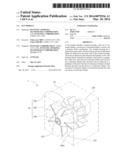
[0019] FIG. 1 is a perspective view showing a fan module according to an embodiment of the invention;
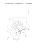
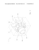
[0020] FIG. 2 is a perspective view showing the fan module in FIG. 1 from another visual angle; and
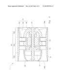
[0021] FIG. 3 is a cross-sectional diagram showing the fan module in FIG. 2.
DETAILED DESCRIPTION
[0022] A plurality of embodiments of the invention will be disclosed below with reference to drawings. For purpose of clear illustration, many details in practice will be described together with the following description. However, it should be understood that, these details in practice are not intended to limit the invention. That is, in some embodiments of the invention, these details in practice are unnecessary. Additionally, for purpose of simplifying drawings, some conventional structures and components in the drawings will be shown in a simple and schematic way.
[0023] A technical aspect of the invention provides a fan module. More specifically, the fan module has a main design for enabling the channel of a module housing to have a function similar to turbo charging, so that the fan module has a capability of providing a high static pressure. Furthermore, the fan module of the invention employs a single dynamic blade combination design to rotate a set of air inflow dynamic blades and a set of supercharging dynamic blades at the same time. Besides that the cost of parts such as the motor and the bearing can be decreased, a larger space also can be provided in the motor housing for the motor. Moreover, in the fan module of the invention multiple sets of stationary blades are disposed in the channel of the module housing and thus are densely arranged together with the air inflow dynamic blades and the supercharging dynamic blades, so as to realize the function of decreasing the backflow of air when the fan is failed.
[0024] FIG. 1 is a perspective view showing a fan module 1 according to an embodiment of the invention. FIG. 2 is a perspective view showing the fan module 1 in FIG. 1 from another visual angle. FIG. 3 is a cross-sectional diagram showing the fan module 1 of FIG. 2.
[0025] As shown in FIGS. 1, 2 and 3, in this embodiment, the fan module 1 includes a module housing 10, a first set of stationary blades 12a, a second set of stationary blades 12b, a motor 14, and a dynamic blade combination 16. The module housing 10 of the fan module 1 has a channel 102. Two ends of the channel 102 are respectively an inlet 100a and an outlet 100b. The first and second set of stationary blades 12a and 12b of the fan module 1 are disposed at the inner wall of the module housing 10 and located in the channel 102. The motor 14 of the fan module 1 includes a motor housing 140 and a rotor 142. The motor housing 140 of the motor 14 is disposed in the channel 102. In an embodiment, the motor housing 140 of the motor 14 is connected with the second set of stationary blades 12b of the fan module 1 and thus is fixed into the channel 102 of the module housing 10.
[0026] As shown in FIGS. 1, 2 and 3, in this embodiment, the dynamic blade combination 16 of the fan module 1 at least includes a hub 160, a first set of dynamic blades 162, and a second set of dynamic blades 164. The hub 160 of the dynamic blade combination 16 is fixedly connected to the rotor 142 of the motor 14 and driven by the motor 14 to rotate. The first and second set of dynamic blades 162 and 164 of the dynamic blade combination 16 surround and are disposed at a periphery of the hub 160. The first set of dynamic blades 162 of the dynamic blade combination 16 is located between the inlet 100a of the module housing 10 and the first set of stationary blades 12a. The second set of dynamic blades 164 of the dynamic blade combination 16 is located between the first set of stationary blades 12a and the second set of stationary blades 12b.
[0027] As shown in FIG. 3, in this embodiment, the channel 102 of the module housing 10 includes a converging section 102a, a diverging section 102b and a supercharged section 102c. One end at the converging section 102a of the channel 102 is connected to the supercharged section 102c and is tapered off from the inlet 100a toward the outlet 100b of the channel 102. The first set of dynamic blades 162 of the dynamic blade combination 16 is located at the converging section 102a of the channel 102. One end at the diverging section 102b of the channel 102 is connected to the supercharged section 102c and is tapered off from the outlet 100b toward the inlet 100a of the channel 102. The supercharged section 102c of the channel 102 is connected between the converging section 102a and the diverging section 102b. Furthermore, the second set of dynamic blades 164 of the dynamic blade combination 16 is located at the supercharged section 102c of the channel 102.
[0028] As shown in FIGS. 1 and 2, in this embodiment, the blade number of the first set of dynamic blades 162 is smaller than the blade number of the second set of dynamic blades 164 in the dynamic blade combination 16. The blade dimension of the first set of dynamic blades 162 is greater than the blade dimension of the second set of dynamic blades 164. In other words, the blade of the first set of dynamic blades 162 of the dynamic blade combination 16 is large, and the arrangement distance between any two of the blades is sparse; while the blade of the second set of dynamic blades 164 is small, and the arrangement distance between any two of the blades is dense. Therefore, when the rotor 142 of the motor 14 rotates, a large amount of air is sucked into the converging section 102a of the channel 102 from the external as much as possible through the first set of dynamic blades 162 of the dynamic blade combination 16, and the air sucked into the channel 102 is further supercharged at the supercharged section 102c of the channel 102 through the second set of dynamic blades 164, so that the fan module 1 has a capability of providing a high static pressure.
[0029] As shown in FIG. 3, in this embodiment, the first and second set of stationary blades 12a and 12b in the fan module 1 are also located at the supercharged section 102c of the channel 102, but the invention is not limited in this regard. For the fan module 1 of the invention, the first set of dynamic blades 162, the first set of stationary blades 12a, the second set of dynamic blades 164, and the second set of stationary blades 12b are densely and sequentially arranged from the inlet 100a toward the outlet 100b in the channel 102 of the module housing 10, so as to realize the function of decreasing the air reflowed into the channel 102 from the outlet 100b when the motor 14 of the fan module 1 is failed.
[0030] As shown in FIGS. 1, 2 and 3, in this embodiment, the hub 160 of the dynamic blade combination 16 is adjacent to the inlet 100a of the module housing 10. Diameters of the part of the hub 160 of the dynamic blade combination 16 located at the converging section 102a of the channel 102 are tapered off toward the inlet 100a. In other words, the distance between the hub 160 of the dynamic blade combination 16 and the converging section 102a of the channel 102 is gradually increased along the direction toward the inlet 100a (i.e., the direction away from the outlet 100b). Additionally, in this embodiment, the motor housing 140 of the motor 14 is adjacent to the outlet 100b. Diameters of the part of the motor housing 140 of the motor 14 located at the diverging section 102b of the channel 102 are tapered off toward the outlet 100b. In other words, the distance between the motor housing 140 of the motor 14 and the diverging section 102b of the channel 102 is gradually increased along the direction toward the outlet 100b (i.e., the direction away from the inlet 100a of the module housing 10).
[0031] Compared to the fan module 1 of the invention, a conventional fan employs two rotors to respectively rotate two sets of fan blades, wherein since the number of rotors is great, the volume of the motor housing of the conventional an and the hub is compressed due to the volume of the two rotors under the same space limitation (that is, in the case that the conventional fan is also disposed in the channel 102 of the module housing 10 of the invention). Therefore, different from the fan module 1 of the invention, the conventional fan cannot make the part of the motor housing 140 adjacent to the outlet 100b and the part of the hub 160 adjacent to the inlet 100a be tapered off outward. If it is wanted to make the conventional fan have a structural design as described above, it is necessary to increase the dimensions of the module housing and motor housing of the conventional fan, which do not comply with the requirement of the space limitation. Relatively, since the fan module 1 of the invention only employs a single rotor 142, a motor 14 having a high efficiency and torsion can be employed under the same space limitation, and meanwhile the design freedom of a circuit is also high.
[0032] Therefore, for the fan module 1 of the invention it may be designed that at the converging section 102a of the channel 102, the diameters of the part of the hub 160 of the dynamic blade combination 16 located at the converging section 102a of the channel 102 are tapered off toward the inlet 100a of the module housing 10; and it may be designed that at the diverging section 102b of the channel 102, the diameters of the part of the motor housing 140 of the motor 14 located at the diverging section 102b of the channel 102 are tapered off toward the outlet 100b of the module housing 10. Therefore, the fan module 1 of the invention can further comply with the spirit of turbo charging and an excellent supercharging effect is achieved.
[0033] As shown in FIGS. 1 and 2, in this embodiment, in order to draw air outside the fan module 1 into the channel 102 of the module housing 10 through the inlet 100a of the channel 102 and exhaust the air through the outlet 100b, the first and second set of dynamic blades 162 and 164 of the dynamic blade combination 16 aslant surround and are disposed at the periphery of the hub 160 substantially along the same trend. An angle may also be included between the blades of the first set of dynamic blades 162 and the blades of the second set of dynamic blades 164 of the dynamic blade combination 16 according to the design requirements (for example, to promote the supercharging effect).
[0034] Additionally, in another embodiment, the trend of the first set of stationary blades 12a disposed in the channel 102 and the trend of the second set of stationary blades 12b disposed in the channel 102 in the fan module 1 are both different from the trend of the first and second set of dynamic blades 162 and 164 surrounding and disposed at the periphery of the hub 160, so as to realize the function of decreasing the air reflowed to the channel 102 from the outlet 100b when the motor 14 of the fan module 1 is failed. In a further embodiment, the first and second set of stationary blades 12a and 12b of the fan module 1 are aslant disposed in the channel 102 substantially along the same trend, but the invention is not limited in this regard. For example, the trend of the first set of stationary blades 12a of the fan module 1 disposed in the channel 102 can be adjusted according to the angle of the air leaving the first set of dynamic blades 162 of the dynamic blade combination 16. Relatively, the trend of the second set of stationary blades 12b of the fan module 1 disposed in the channel 102 cab be adjusted according to the angle of the air leaving the second set of dynamic blades 164 of the dynamic blade combination 16.
[0035] In this embodiment, the fan module 1 of the invention may employ a design of outer rotor, so as to have advantages such as simple winding and magnet cost savings, but the invention is not limited in this regard. In a further embodiment, if the difficulty of winding and the cost are not considered, the fan module 1 of the invention also can employ a design of inner rotor.
[0036] It can be obviously seen from the above detailed description of specific embodiments of the invention that, the fan module of the invention has a main design for enabling the channel of the module housing to have a function similar to turbo charging, so that the fan module has a capability of providing a high static pressure. Furthermore, the fan module of the invention employs a single dynamic blade combination design to rotate a set of air inflow dynamic blades and a set of supercharging dynamic blades simultaneously. Besides that the cost of parts such as the motor and the bearing can be decreased, a large space also can be provided in the motor housing for the motor. In other words, the fan module of the invention can employ the motor having a high efficiency and torsion under the same space limitation, and meanwhile the design freedom of a circuit is also high. Moreover, for the fan module of the invention multiple sets of stationary blades are disposed in the channel of the module housing and thus are densely arranged together with the air inflow dynamic blades and the supercharging dynamic blades, so as to realize the function of decreasing the backflow of air when the fan is failed.
[0037] Although the invention has been disclosed with reference to the above embodiments, these embodiments are not intended to limit the invention. It will be apparent to those of skills in the art that various modifications and variations can be made without departing from the spirit and scope of the invention. Therefore, the scope of the invention shall be defined by the appended claims.
User Contributions:
Comment about this patent or add new information about this topic:
Images included with this patent application:
 |  |
 |  |
| New patent applications in this class: | |
| Date | Title |
|---|---|
| 2022-05-05 | Fabricated cmc nozzle assemblies for gas turbine engines |
| 2019-05-16 | Ogv electroformed heat exchangers |
| 2018-01-25 | Intermediate case for an aircraft turbomachine made from a single casting with a lubricant duct |
| 2018-01-25 | Turbine vane with coupon having corrugated surface(s) |
| 2018-01-25 | Blade with internal rib having corrugated surface(s) |
| New patent applications from these inventors: | |
| Date | Title |
|---|---|
| 2015-04-30 | Donor-acceptor alternating conjugated polymer and solar cell device manufactured by using the same |
| 2014-06-12 | Translation system and method thereof |
| 2014-06-05 | System and method for testing sub-servers through plurality of test phases |
| 2014-06-05 | Motherboard in a server |
| 2014-05-29 | Cloud-based route planning system and method thereof |
| Top Inventors for class "Rotary kinetic fluid motors or pumps" | |
| Rank | Inventor's name |
|---|---|
| 1 | Gabriel L. Suciu |
| 2 | Frederick M. Schwarz |
| 3 | United Technologies Corporation |
| 4 | Brian D. Merry |
| 5 | Craig M. Beers |