Patent application title: Mail Box Shield
Inventors:
Charles O. Pickens (Farmington, CT, US)
IPC8 Class: AA47G29122FI
USPC Class:
232 17
Class name: Deposit and collection receptacles letter boxes
Publication date: 2014-03-13
Patent application number: 20140069996
Abstract:
The objective of the invention is to deflect snow thrown by a snow plow
to prevent damage and lack of accessibility to mail boxes. The drawing
scale is 1:8. Engineered drawings now completed. A model has been
fabricated and constructed. A plastics engineer is required to determine
the proper plastic/synthetic materials and the thicknesses of the side
walls and bracing. Changes to follow.Claims:
1. Shields roadside mail boxes from snow plowing damage utilizing its
leading edge construction.
2. Existing home made devices are unstable, easily destructible and difficult to manage in set-up, take-down and storage.
3. The Shield is medium weight, sturdy, durable, indestructible, easily erected and taken down for storage.
Description:
[0001] The invention is a shield that protects roadside mail boxes from
snow plowing damage by deflecting oncoming snow with its leading edge
angled front design.
BRIEF DESCRIPTION
[0002] The device is comprised of the following components as pictured in drawings as follows:
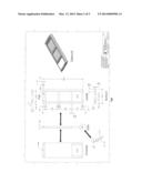
[0003] FIG. 1A depicts the assembled view of all components as they would be when erected.
[0004] FIG. 1B depicts the exploded view of the component parts prior to assembly with the stakes and stock carriage bolts, nuts and washers.
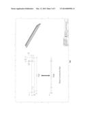
[0005] FIG. 2 depicts the inside, outside, top, bottom and side views of the sidewall (2) that are interchangeable to be fastened top and bottom with the rear connector bars and front connector plates with carriage bolts.
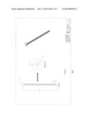
[0006] FIG. 3 depicts the rear connector bar (2) that are interchangeable and fastened at the top and bottom to the trailing edges of the sidewalls with carriage bolts.
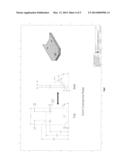
[0007] FIG. 4 depicts the front connector plate (2) that are interchangeable and fastened to the top and bottom to the leading edges of the sidewalls with carriage bolts.
[0008] FIG. 5 depicts the stake (5) that are interchangeable and driven into the ground thru the predrilled, angled holes in the sidewalls and bottom front connector plate.
[0009] Optional--1 Stake and adjustable tension strap (stock item, optional use).
[0010] All elements are necessary. Additional optional reflectors, numbers and art work may be affixed.
[0011] The leading edge of the Mail Box Shield deflects snow off both sides. Snow accumulating at open side bottoms freezes and adds reinforcement.
[0012] Manufacturer must injection mold or press mold the sidewall and rear connector bar and front connector plate of plastic/synthetic material which withstands low temperatures and blunt force. Stake must be formed from extruded or molded similar material.
[0013] To erect the shield before ground freezes, level a 24 inch semi-circle on the ground surface on the oncoming traffic side of mail box.
[0014] Assemble the Mail Box Shield by attaching the interchangeable 2 sidewalls with the interchangeable 2 rear connector bars and interchangeable 2 front connector plates using the 8 carriage bolts. Position at the oncoming side of the mail box and drive Stakes thru the angled bottom holes in the sidewalls into ground.
[0015] After the ground thaws pull the stakes, unbolt the connector bars, and repack and store for spring-summer-autumn season.
User Contributions:
Comment about this patent or add new information about this topic:
| People who visited this patent also read: | |
| Patent application number | Title |
|---|---|
| 20140352398 | device and method for checking an assembly wrench |
| 20140352397 | Optical Fluid Analyzer with Calibrator and Method of Using Same |
| 20140352396 | PLAUSIBILITY CHECK OF A SENSOR SIGNAL |
| 20140352395 | PRESS DIE |
| 20140352394 | PRESS DIE |
Images included with this patent application:
 |  |
 |  |
 |
| Similar patent applications: | |
| Date | Title |
|---|---|
| 2015-04-23 | Multifunctional postbox having light-emitting diode display unit and using solar cell module |
| 2015-11-12 | Mailbox system having a removable mailbox |
| New patent applications in this class: | |
| Date | Title |
|---|---|
| 2016-12-29 | Smart mailbox, smart mailbox system and related method |
| 2015-10-22 | Theft-resistant wall mount mailbox |
| 2013-04-25 | Mailbox accessory device |
| 2013-01-24 | Moveable mailbox tray |
| 2012-11-08 | Secure deposit box and method of construction thereof |
| New patent applications from these inventors: | |
| Date | Title |
|---|---|
| 2016-03-17 | Mail box shield |
| Top Inventors for class "Deposit and collection receptacles" | |
| Rank | Inventor's name |
|---|---|
| 1 | David J. Bolles |
| 2 | Takashi Matsuno |
| 3 | Ryszard K. Mikolajczyk |
| 4 | Kenji Kimoto |
| 5 | Leon Saltsov |