Patent application title: Inertial Dumbbell Exercise Device
Inventors:
Michael Wheler (Oshawa, CA)
IPC8 Class: AA63B2100FI
USPC Class:
482110
Class name: Exercise devices user manipulated force resisting apparatus, component thereof, or accessory therefor utilizing inertial force resistance
Publication date: 2014-03-06
Patent application number: 20140066269
Abstract:
An inertial dumbbell exercise device including a first and second weight
assembly disposed endwise upon a handle, each of said weight assemblies
including a rod disposed perpendicularly and slidably upon the handle, an
interchangeable pair of weights disposed endwise upon said rod, and an
interchangeable rubber sleeve disposed between each of said pair of
weights and said handle, wherein movement of the handle in a first
direction accelerates one of said pair of weights from a first position
to a second position against the elastic force of the respective rubber
sleeve, movement of the handle in a second and opposite direction
accelerates the other of said pair of weights from a first position to a
second position against the elastic force of the respective rubber
sleeve, and the compressive resistance of the rubber sleeve is
adjustable, as desired.Claims:
1. An inertial dumbbell exercise device comprising: a handle having a
first end and a second end; a first weight assembly movably disposed on
the first end and a second weight assembly movably disposed on the second
end, each of said first and second weight assemblies comprising: a rod
moveably disposed perpendicularly through the handle; a pair of weights
disposed at either end of the rod; and a rubber sleeve disposed around
the rod between the handle and each of the pair of weights; wherein said
rod is slidably moveable within the handle whereby one of the pair of
weights compressibly engages the respective rubber sleeve when the handle
is moved in a first direction and the other of the pair of weights
compressibly engages the respective rubber sleeve when the handle is
moved in a second direction whereby the elasticity of each respective
rubber sleeve rebounds the respective weight without the need of springs.
2. The inertial dumbbell exercise device of claim 1 wherein each of the pair of weights of each of the first and second weight assemblies is interchangeable with alternate weights having a different mass.
3. The inertial dumbbell exercise device of claim 1 wherein each respective rubber sleeve is interchangeable with alternate runner sleeves having a different elasticity and compressive resistance.
4. The inertial dumbbell exercise device of claim 1 wherein each of the first and second weight assemblies further comprises a pair of moveable collars disposed around the rod on either side of the handle, each of said moveable collars disposed proximal the handle.
5. The inertial dumbbell exercise device of claim 4 further including at least one dial disposed upon the handle, said dial operationally communicating with each of said moveable collars wherein turning said dial between a plurality of settings moveably orients each collar to compressibly engage the respective rubber sleeve between a maximum compression and a maximum decompression whereby the acceleration of the respective weight assembly is rendered more and respectively less difficult by means of the pair of collars compressing and respectively decompressing each respective rubber sleeve.
6. The inertial dumbbell exercise device of claim 5 wherein one of said dials is disposed on the handle at the first and second end respectively.
7. The inertial dumbbell exercise device of claim 6 wherein each of the first and second weight assemblies further includes a pair of brace members in operational communication with the dial and each of the respective pair of moveable collars, wherein rotation of the dial in a first direction extends each of the pair of brace members away from each other and each of the respective pair of moveable collars is pushed away from the handle towards each of the respective pair of weights whereby the respective rubber sleeve is compressed.
8. The inertial dumbbell exercise device of claim 7 wherein rotation of the dial in a second direction pulls each of the pair of brace members towards each other whereby each of the pair of moveable collars is moved towards the handle and each respective rubber sleeve is decompressed.
9. The inertial dumbbell exercise device of claim 8 wherein the dial is positional between a plurality of settings whereby the pair of brace members are moved through a plurality of discrete extensions and each of the pair of moveable collars is moveable to a specific position along the length of the rod whereby each of the respective rubber sleeves is compressed an amount relative to the specific position of each of the pair of moveable collars.
10. An inertial dumbbell exercise device comprising: a handle having a first end and a second end; a first weight assembly movably disposed on the first end and a second weight assembly movably disposed on the second end, each of said first and second weight assemblies comprising: a rod moveably disposed perpendicularly through the handle; a pair of moveable collars disposed around the rod on either side of the handle, each of said moveable collars disposed proximal the handle; a pair of weights disposed at either end of the rod; a rubber sleeve disposed around the rod between the moveable collar and each of the pair of weights; a dial disposed upon the handle first and second end; a pair of brace members disposed upon said dial connecting said dial to each respective pair of moveable collars; wherein said rod is slidably moveable within the handle whereby one of the pair of weights compressibly engages the respective rubber sleeve when the handle is moved in a first direction, and the other of the pair of weights compressibly engages the respective rubber sleeve when the handle is moved in a second direction; wherein the dial is rotatable between a plurality of settings that alternately retract and extend each of the pair of brace members whereby each of the respective pair of moveable collars is moved between a plurality of positions that alternately compress and decompress each respective rubber sleeve between a maximum compression and a maximum decompression whereby the force of accelerating each of the pair of weights against the respective rubber sleeve is respectively increased and decreased.
11. The inertial dumbbell exercise device of claim 10 wherein each of the pair of weights of each of the first and second weight assemblies is interchangeable with weights having a different mass.
12. The inertial dumbbell exercise device of claim 11 wherein each respective rubber sleeve is interchangeable with alternate rubber sleeves having different elasticity and compressive resistance.
Description:
BACKGROUND OF THE INVENTION
[0001] Various types of inertial exercise devices are known in the prior art, most requiring the use of fitted springs to elastically resist the acceleration of a weight accelerated between a first position and second position. This elastic resistance requires the application of additional force to accelerate the weight to overcome the resistance, thereby engendering increased physical exertion relative the mass accelerated. However, what is needed is an inertial dumbbell exercise device that enables setting a range of resistance, whereby the acceleration of each of a pair of weights of each of a first and second weight assembly requires more or less force relative the setting selected.
[0002] The present inertial dumbbell exercise device, then, includes a first and second weight assembly disposed upon a respective first and second end of a handle, each of said weight assemblies including a rod disposed perpendicularly and slidably thereupon, a pair of weights disposed endwise upon said rod, and a rubber sleeve disposed between each of said pair of weights and said handle, wherein movement of the handle in a first direction accelerates one of said pair of weights from a first position to a second position against the elastic force of the respective rubber sleeve, and movement of the handle in a second and opposite direction accelerates the other of said pair of weights from a first position to a second position against the elastic force of the respective rubber sleeve, whereby increased exertion is required to accelerate each of said pair of weights relative the force required to accelerate an equivalent mass absent the action of said rubber sleeve, and whereby each of said pair of weights and each respective rubber sleeve is interchangeable to provide for increased exertion required to accelerate said weights between the first position and the second position.
FIELD OF THE INVENTION
[0003] The present invention relates to an inertial dumbbell exercise device, and more particularly, to an inertial dumbbell exercise device that includes a first and second weight assembly disposed upon a respective first and second end of a handle, each of said weight assemblies including a rod disposed perpendicularly and slidably thereupon, a pair of weights disposed endwise upon said rod, and a rubber sleeve disposed between each of said pair of weights and said handle, wherein movement of the handle in a first direction accelerates one of said pair of weights from a first position to a second position against the elastic force of the respective rubber sleeve, and movement of the handle in a second and opposite direction accelerates the other of said pair of weights from a first position to a second position against the elastic force of the respective rubber sleeve, whereby increased exertion is required to accelerate each of said pair of weights relative the force required to accelerate an equivalent mass absent the action of said rubber sleeve, and each of said pair of weights of each of the first and second weight assemblies and each respective rubber sleeve is interchangeable to provide for increased exertion required to accelerate said weights between the first position and the second position.
SUMMARY OF THE INVENTION
[0004] The general purpose of the inertial dumbbell exercise device, described subsequently in greater detail, is to provide an inertial dumbbell exercise device which has many novel features that result in an inertial dumbbell exercise device which is not anticipated, rendered obvious, suggested, or even implied by prior art, either alone or in combination thereof.
[0005] The present device provides an inertial exercise tool that requires physical exertion to accelerate a first and second weight assembly, disposed endwise upon a handle, against the elastic action of a respective rubber sleeve. The first weight assembly is moveably disposed upon a first end of the handle and the second weight assembly is moveably disposed upon a second end of the handle. Each of the first and second weight assemblies includes a rod slidably disposed perpendicularly at each respective first and second end of the handle. A pair of weights is disposed endwise upon said rod. Each of a pair of moveable collars is disposed upon the rod between each of the pair of weights and the handle. A rubber sleeve is disposed between each of the pair of weights and each of the pair of moveable collars.
[0006] Each of the pair of weights of each of the first and second weight assemblies is moveable between a first position and a second position. When the handle is moved in a first direction, one of the said pair of weights is accelerated from a first position to a second position. Said one of said pair of weights is accelerated to compress the respective rubber sleeve, which rubber sleeve elastically resists compression. Increased force is therefore required when said one of said pair of weights is accelerated against said rubber sleeve than would otherwise be required to accelerate said one of said pair of weights to the second position absent the action of the rubber sleeve.
[0007] When the handle is moved in a second direction, said second direction opposite the first direction, the other of said pair of weights is accelerated from the first position to the second position against the action of the respective rubber sleeve, in like manner as described previously for said one of said pair of weights. Thusly, movement of the handle back and forth accelerates each of the pair of weights of each of the respective first and second weight assemblies back and forth between the first and second position whereby, when one of the pair of weights is moved to the second position, the other of said pair of weights is moved to the first position, and vice versa, each of the pair of weights engaging and compressing the respective rubber sleeve when moved to the respective second position.
[0008] A dial is included disposed endwise on each of the first and second ends of the handle. Said dial is in operational communication with a pair of brace members connected to each of the respective pair of moveable collars disposed upon each of the first and second weight assemblies. When the dial is rotated in a first direction, each of the pair of brace members is extended outwards away from the handle, and each of the pair of moveable collars is moved to a position less proximal the handle, a position that compressibly engages each of the pair of moveable collars with each respective rubber sleeve disposed between each of the pair of weights and each of the respective pair of moveable collars. When the dial is rotated in a second direction, each of the pair brace members is retracted towards the handle by the rotational action of the dial, and each of the pair of moveable collars is pulled to a position more proximal the handle.
[0009] The dial is configured to rotate through a plurality of settings wherein each of the pair of moveable collars is moveable between a plurality of positions between each of the pair of weights and the handle, whereby each respective rubber sleeve is compressed between a maximum compression and a maximum decompression. Each respective first and second weight assembly is most easily accelerated to the second position when each respective rubber sleeve disposed thereupon is maximally compressed and each respective first and second weight assembly is least easily accelerated to the second position when each respective rubber sleeve is maximally decompressed. Therefore, a range of elastic resistance of each respective rubber sleeve is selectable by means of the dial disposed to rotatably engage each of the pair of moveable collars with each respective rubber sleeve between a maximum compression and a maximum decompression.
[0010] It should be noted that no springs are required for operation of the present inertial dumbbell exercise device. Each respective rubber sleeve provides the necessary elasticity to resist compression when one of the pair of weights is accelerated against said rubber sleeve. Said resistance requires additional physical exertion to accelerate said one of said pair of weights relative the acceleration of an equivalent mass absent the resistive action of said rubber sleeve.
[0011] Moreover, it is considered that each of the pair of weights of each of the first and second weight assemblies may be interchangeable with alternately available weights having different masses whereby the force required to accelerate said weights is increased and alternately decreased, as desired, depending on the weights selected. Each respective rubber sleeve, also, is considered interchangeable with additional sleeves having an increased or decreased compressive resistance to the acceleration of said weights whereby increased or decreased force is required to accelerate said weights to the second position against the action of said rubber sleeve, as desired, depending on the particular rubber sleeve selected.
[0012] Thus has been broadly outlined the more important features of the present inertial dumbbell exercise device so that the detailed description thereof that follows may be better understood and in order that the present contribution to the art may be better appreciated.
[0013] Objects of the present inertial dumbbell exercise device, along with various novel features that characterize the invention are particularly pointed out in the claims forming a part of this disclosure. For better understanding of the inertial dumbbell exercise device, its operating advantages and specific objects attained by its uses, refer to the accompanying drawings and description.
BRIEF DESCRIPTION OF THE DRAWINGS
Figures
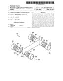
[0014] FIG. 1 is an isometric view.
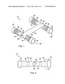
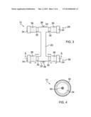
[0015] FIG. 2 is an end view.
[0016] FIG. 3 is a top view.
[0017] FIG. 4 is a cross-section view taken along the line 4-4 of FIG. 2.
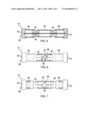
[0018] FIG. 5 is a cross-section view taken along the line 5-5 of FIG. 3.
[0019] FIG. 6 is a partial cross-section view detailing the action of a dial operationally communicating with each of a pair of moveable collars by means of a pair of brace members in a retracted position.
[0020] FIG. 7 is a partial cross-section view detailing the action of the dial operationally communicating with each of the pair of moveable collars by means of the pair of brace members in an extended position.
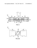
[0021] FIG. 8 is a longitudinal cross-section view of one of a pair of weight assemblies.
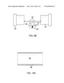
[0022] FIG. 9A is a top view detailing the action of the dial rotationally engaging the pair of brace members to retract each of the pair of moveable collars.
[0023] FIG. 9B is a detail view of the dial.
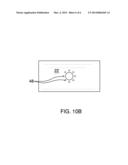
[0024] FIG. 10A is a cross-section view of a first end of a handle with the dial removed.
[0025] FIG. 10B is an end view of a first end of a handle with the dial removed.
DETAILED DESCRIPTION OF THE DRAWINGS
[0026] With reference now to the drawings, and in particular FIGS. 1 through 10 thereof, example of the instant inertial dumbbell exercise device employing the principles and concepts of the present inertial dumbbell exercise device and generally designated by the reference number 10 will be described.
[0027] Referring to FIGS. 1 through 10 a preferred embodiment of the present inertial dumbbell exercise device 10 is illustrated.
[0028] The present inertial dumbbell exercise device 10 has been devised to provide an exercise tool that requires human force to accelerate each of a first weight assembly 26 and a second weight assembly 28 disposed endwise upon a handle 20 against a respective rubber sleeve 36 which rubber sleeve 36 elastically compresses to resist the movement of said weight assemblies 26, 28. Therefore, the energy required to accelerate each of the first and second weight assemblies 26, 28 between a first position, with each respective rubber sleeve 36 decompressed, and a second position, with each respective rubber sleeve 36 compressed, against the elasticity of each respective rubber sleeves 36, creates muscle mass in a body using the inertial dumbbell exercise device 10. Resultantly, less mass is required upon the handle 20 than would otherwise be required because the inertia of the weight assemblies 26, 28 requires additional force to accelerate said weight assemblies 26, 28 against each respective rubber sleeve 36 relative the force required to accelerate said weight assemblies 26, 28 without compressibly engaging said respective rubber sleeve 36.
[0029] Discussing now the preferred embodiment of the instant device 10, the inertial dumbbell exercise device 10 includes a handle 20 having a first end 22 and a second end 24. A first weight assembly 26 is movably disposed on the first end 22 and a second weight assembly 28 is likewise movably disposed on the second end 24. Each of said first and second weight assemblies 26, 28 includes a rod 30 moveably disposed perpendicularly through the handle 20, a pair of moveable collars 32 disposed around the rod 30 on either side of the handle 20, each of said moveable collars 32 disposed proximal the handle 20, a pair of weights 34 disposed at either end of the rod 30, and a rubber sleeve 36 disposed between each moveable collar 32 and each of the pair of weights 34.
[0030] Said rubber sleeve 36 is elastically compressible and resists compression by exerting a force opposite the direction in which said rubber sleeve 36 is compressed. It should be noted that the term "rubber" as used herein is not meant to limit said rubber sleeve 36 to fabrication from rubber per se, but the term "rubber" is taken to include rubberlike materials, polymeric substances, and other compressibly elastic materials that may be suited to the intended function of said rubber sleeve 36 as disposed to elastically resist compression when compressed in the manner subsequently described.
[0031] The rod 30 of each of the first and second weight assemblies 26, 28 is slidably moveable within the handle 20 respective first and second end 22, 24. When the handle 20 is moved in a first direction, one of the pair of weights 34 compressibly engages the respective rubber sleeve 36. When the handle 20 is moved in a second direction, the other of the pair of weights 34 compressibly engages the other respective rubber sleeve 36. Force is therefore required to move each of the pair of weights 34 to compress each respective rubber sleeve 36 when moving each of the pair of weights 34 from a respective first position to the respective second position. Physical exertion is therefore required to operate the device 10, and the action of each respective rubber sleeve 36 compressibly resisting the acceleration of each of the pair of weights 34 of each of the respective first and second weight assemblies 26, 28 requires additional exertion relative the exertion required to otherwise accelerate an equivalent mass absent said respective rubber sleeve 36.
[0032] To control the resistance applied to said moveable collars 32 when accelerating each of said pair of weights 34 against the respective rubber sleeve 36, a dial 38 is disposed upon the handle 20 at the first end 22 and the second end 24. The dial 38 is in operational communication with each respective pair of moveable collars 32. A pair of brace members 40 is disposed upon the dial 38, said brace members 40 connecting said dial 38 to each respective pair of moveable collars 32. The dial 38 is rotatable between a plurality of settings 42 that extend each of the pair of brace members 40 when the dial 38 is rotated in a first direction and retract each of the pair of brace members 40 when the dial 38 is rotated in a second direction (see FIGS. 6 and 7). Each respective pair of moveable collars 32 is thereby moveable between a plurality of positions that alternately compress and decompress each respective rubber sleeve 36 to alter the difficulty of accelerating each of the pair of weights 34 against the respective rubber sleeve 36.
[0033] The dial 38 may include a plurality of locking teeth 44 configured to releasably secure the dial 38 within a set position within the handle 20 (see FIG. 9B). A spring member 46 may be included to releasably secure the dial 38 in position once the dial 38 has been moved to a specific position. The dial 38 may therefore be retractably housed upon the handle 20, wherein the dial 38 is pulled outwards, away from the respective first and second end 22, 24, rotated to the desired setting, and then retracted to contact the handle 20 with each of the locking teeth 44 disposed in each of a plurality of holes 48 configured to receive each of the plurality of locking teeth 44 therein. the dial 38 is thusly releasably secured in position by means of the locking teeth 44 and each respective pair of locking collars 32 is moved to the desired position between the maximum compression and maximum decompression of each respective rubber sleeve 36.
[0034] It should be noted that interchangeable weights are envisioned to be included with the device 10, whereby each of the pair of weights 34 of each of the respective first and second weight assemblies 26, 28 may be interchanged with weights having more or less mass. Each respective rubber sleeve 36 may also be replaced with alternate rubber sleeves of varying elasticity to create a greater or lesser resistance to accelerating the mass of each of said pair of weights 34, as desired. Therefore, ranges of forces are selectable to accelerate the first and second weight assemblies 26, 28, as desired when using the device 10 among a plurality of exercises.
User Contributions:
Comment about this patent or add new information about this topic:
Images included with this patent application:
 |  |
 |  |
 |  |
 |
| Similar patent applications: | |
| Date | Title |
|---|---|
| 2013-05-02 | Multiple pulley system exercise device |
| 2013-05-02 | Abdominal exercise device having figure shaping function |
| 2014-05-01 | Therapeutic exercise device |
| 2014-01-02 | Progressive resistance exercise device |
| 2014-01-23 | Dumbbell retention device |
| New patent applications in this class: | |
| Date | Title |
|---|---|
| 2019-05-16 | Muscle exercising apparatus |
| 2016-01-07 | Exercise device and associated methods |
| 2015-01-29 | Gyroscopic apparatuses and methods of using same |
| 2015-01-15 | Fitness hoop having variable impact force |
| 2014-11-20 | Waist exercise device |
| Top Inventors for class "Exercise devices" | |
| Rank | Inventor's name |
|---|---|
| 1 | William T. Dalebout |
| 2 | Scott R. Watterson |
| 3 | Raymond Giannelli |
| 4 | Leao Wang |
| 5 | Bruce Hockridge |