Patent application title: SUBSURFACE INTELLIGENT CLUSTER OF CURRENT ENERGY CONVERTERS
Inventors:
Yin Shang Soong (Lancaster, PA, US)
IPC8 Class: AF03B1310FI
USPC Class:
290 54
Class name: Prime-mover dynamo plants fluid-current motors
Publication date: 2014-03-06
Patent application number: 20140062091
Abstract:
A subsurface floating cluster of current energy converters is disclosed.
A cluster consists of many nodes on a single mooring cable. Two
converters, rotating in opposite direction, are connected as a pair. At
least two pairs, four converters, are connected to each node. Each
converter consists of a rotor with curved blades, a transmission, and an
electrical generator. A computer on the mother ship, that tows the
cluster, controls the rotating rate of every rotor in the cluster. Each
node moves vertically or horizontally according to the
rotation-rate-differential in each pair of rotors. Each node seeks and
remains in peak velocity region, or at a predetermined water depth, to
convert kinetic energy to electricity with an optimal efficiency. This
invention has characteristics of simplicity in design, using artificial
intelligence to achieve high efficiency in peak speed region of an ocean
current, incremental capacity, and mobility.Claims:
1. Two ocean current energy converters are connected as a pair
comprising: each said converter has a rotor and a compartment that houses
an electrical generator and transmission gears and sensors; the curved
blades of said rotor have different drag coefficients wherein the rotor
rotates in water flow; said two converters are mated so that the two said
rotors only rotate in opposite directions, wherein one rotates clockwise
the other always rotates counter-clockwise; each said rotor's rotation
turns the attached said generator to generate electrical power with said
transmission; and each said converter is equipped with at least one
pressure sensor and sensors for measuring said rotor's rotation rate.
2. Each said pair of ocean energy converters of claim 1, wherein another pair is attached on the other side of a node, comprises: each said node has an even number of said pairs to make a working node; each said node and each said converter are designed to be equal to average water density and therefore neutrally buoyant in water; each said node has a spool in the compartment to retract or release a connection cable; and each said node is equipped with at least one pressure sensor and at least one flow meter.
3. The said connection cable of claim 2 between each said node and a computer that is mounted on a platform comprises: data and power transmission between each said node and said computer; said computer sends commands to each said transmission in each said converter to change the said rotor's rotation rate; said computer sends commands to said converter to apply a braking mechanism to change the said rotors rotation rate; a computer algorithm in said computer is to keep each said node to remain in peak speed region of ocean current to achieve an optimal efficiency of energy conversion and to keep each said node at a predetermined water depth; each said node sends current speed data and water depth data to said computer with said connection cable; and each said converter sends water depth data and rotation rate data to said computer.
4. The said platform of claim 3, wherein said computer is mounted, comprises a movable platform: an anchored surface ship: and an anchored submersible vessel.
5. The said platform of claim 3, wherein said computer is mounted. comprises a permanent unmovable platform; an oil-drilling rig; an outcrop on ocean floor; an island; and a seamount.
6. The said pair of ocean energy converters of claim 1 is designed to be two identical modules with one said electrical generator and one said gear-transmission in each module.
7. The said pair of ocean energy converters of claim 1 is designed to be two converters sharing one said electrical generator and with two separate said gear-transmission.
8. Small scale version of said pair of ocean energy converters of claim 1 is portable and is carried in a suitcase; the said portable converters are designed with extendable blades to increase power outputs in river flow and coastal current.
Description:
BACKGROUND OF THE INVENTION
[0001] 1. Field Of The Invention
[0002] The present invention relates generally to a mooring system and supporting devices to convert ocean current energy to electricity.
[0003] 2. Description Of Related Art
[0004] The use of kinetic energy in water flow has been known for many years in human history. The physical principle is simple and it is easy to construct a machine to tap the river flow energy. Ancient people used flow in river to do work for them with a water wheel. There has been, however, little advance in using ocean current energy although various ideas were known since the discovery of strong current such as the Gulf Stream. One critical difficulty is the fact that ocean currents change with time in location, depth and speed. Many patented designs, such as in Haining (U.S. Pat. No. 5,440,176) and Geary, (U.S. Pat. No. 6,006,518) are anchored devices on the seafloor at a fixed location. Mouton (U.S. Pat. No. 4,219,303) and Jennings and Martin (U.S. Pat. No. 7,470,086) patented floating submarine turbines that are also anchored on the ocean floor by cables. None of the patented inventions can intelligently seek and remain in the peak velocity region of ocean currents. The present invention has a built-in intelligence to overcome the critical difficulty to achieve an optimal efficiency to convert current energy to electricity.
BRIEF SUMMARY OF THE INVENTION
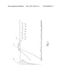
[0005] The invention relates to a configuration of a cluster of current energy converters. The cluster is towed by a cable behind a mother ship 1 which is anchored in a current 2 in FIG. 1. The cluster consists a serial or nodes 3 connected by a single cable 4 that serves both for electric power and signal transmissions. The current energy converters, equipped with rotors 5, 6 and connecting generators 7, 8 attached to each node 3 like wings to an airplane body FIG. 2. Each rotor looks like a so-called Savonius wind turbine (only two blades shown for illustration). As each rotor rotates in current, the connecting generator converts kinetic energy to electricity. The two rotors in each pair FIG. 3 always rotate in opposite direction, one 5 in clockwise direction but the other 6 in counter-clockwise direction. The opposite rotation is due to the drag force difference on the two rotors' blades. There is no net torque on the node from the two opposing rotations if they rotate at the same rate. There are at least two pairs, four converters, one pair on each side, for a working node FIG. 2. There could be more than two pairs on each node to increase the capacity of power generation. But there must be equal number of pairs on both side of a node for symmetry. There could be many nodes in the cluster to further increase the total power generation. Each node and each converter are designed to be near average water density and therefore neutrally buoyant. A node, with the same number of pairs of converters on both sides of the node, behaves like an `airplane flying` in water.
[0006] In each pair, the two rotors will rotate independently. If both rotors in the pair rotate at the same rate, this pair will remain at the same depth in a current. However, if one rotor rotates faster than the other one in the pair, this pair will either ascend or descent, according to Bernoulli principle (Batchelor, 2000) that says pressure is higher for slower flow, and vice versa, around an immersed body in fluid. When the average flow speed above the pair is higher than that below the pair, this `wing` will ascend because the pressure is higher below the `wing`. This is the same principle for an airplane to fly in air due to an asymmetrical profile of the aerofoil. The rotating rate of a rotor is determined by the resistance of the attached generator through a transmission in a given current. When the resistance from the generator increases, the rotor rotates slower for the same water flow speed. The rotation can also be slowed down by an auxiliary brake. The other `wing`, the pair of converters on the other side of the node, also ascends or descends depending on the relative rotating rate of the two rotors in that pair. If both `wings` descend, this node dives to a deeper water, and the node ascends toward surface if both `wings` ascend. If one `wing` ascends but the other wing descends, the two pairs rotate to an angle relative to the horizon, and consequently move horizontally. Each rotor is equipped with a pressure sensor and a rotation speedometer. Each node is equipped with a pressure sensor and a flow meter. There is an electric water pump in the node with two nozzles, one pointing downward 12 and one pointing upward 13. The nozzles are used for minute adjustment of the node depth. The towing cable 4 is retracted and released for retrieval and deployment, respectively, from a spool in the node 3 compartment. Whenever the ocean current changes its speed, the flow meter on the node sends the new data to the mother ship computer. The computer controls each node to move vertically or horizontally for the current energy converters to remain in the peak velocity region. An optimal efficiency for the current energy generation is achieved by this intelligent mooring cluster. The cluster is kept at a subsurface water depth to avoid any vessels or fishing operations at ocean surface.
BRIEF DESCRIPTION OF THE DRAWINGS
[0007] FIG. 1 shows an anchored mother ship 1 with a cluster of current energy converters. A typical speed profile in a strong ocean current 2 is shown on the left side of the figure. Notice the peak speed may not be at the sea surface but below the surface.
[0008] FIG. 2 shows a node 3 with four current energy converters 5,6. Two converters attach on each side of the node 3 as a pair. Each converter has a rotor and a compartment for an electrical generator, transmission gears and sensors. The two rotors always rotate independently in opposite direction in the pair, the node is equipped with an electric water pump and two nozzles, one 13 upward and one 12 downward, for minute adjustments of the node in water depth. The towing cable 4 transmits both electrical power and digital signal between each node and the mother ship. The cable 4 is retractable on a spool in the node compartment.
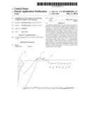
[0009] FIG. 3 shows a pair of two converters with spinning rotors 5,6. The average flow speed above the pair is labeled Va and the average flow speed below the pair is labeled Vb). The average water pressure above the pair is labeled Pa and the average water pressure below the pair is labeled Pb.
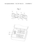
[0010] FIG. 4 shows four portable converters and a small site node 10 that can be carried in a suitcase 11. There are extendable blades 9 on the portable rotors to increase power generation capacity.
DETAILED DESCRIPTION OF THE PREFERRED EMBODIMENT
[0011] The invention relates to an application of Bernoulli principle on each pair of rotors that rotate in opposite direction independently. FIG. 3 is used to illustrate this principle in details. When current flow pushes both rotors into rotation in opposite directions because of the drag force is larger on the top blade than that on the bottom blade in rotor 5 but it is exactly the opposite in rotor 6. The two rotors are rotating with the same rate when the resistances due to respective electrical generators 7, 8 are the same. The average flow speeds above and below the two rotors are the same because the two rotors rotate in opposite directions at the same rate. Therefore, Va equals Vb, that leads to Pa equals Pb according to Bernoulli equation, Eq. 1.
0.5 (Va)2+Pa/ρ=0.5 (Vb)2+Pb/ρ Eq. 1
where Va and Vb are speed, Pa and Pb are pressure, and ρ is water density.
[0012] However, rotor 5 rotates slower when the resistance increases in the connecting generator 7. This is accomplished by the mother ship computer that sends a command to change the gear ratio in the transmission (not shown) between rotor 5 and its electrical generator 7. But the resistance in generator 8 for rotor 6 is not changed, the rotor 6 does not change its rotating rate. As a result, the average flow speed, Va, slows down above the pair. The average flow speed, Vb, also slows down, but not as much as Va because the curved blades always cause a larger drag force when they rotate to be above the rotating axial in rotor. The Bernoulli equation Eq. 1 dictates that Pa larger than Pb when Va is smaller than Vb. The larger average pressure, Pa, consequently, pushes the pair downward into deeper water. Based on the same principle, if the rotor 6, rotating counter-clockwise, has a slower rate than that of rotor 5, Vb is smaller than Va for a constant water density. Consequently, Pb is larger than Pa, this pair moves upward into shallower water. The mother ship computer makes adjustment on the gear ratio in transmission at each converter to change its rotation rate, and therefore controlling the depth of the pair. The computer also controls the other `wing` such that the node can be commanded to move up or down, vertically. The node moves horizontally by tilting the `wings` just like an airplane when one pair moves upward but the other pair moves downward. The computer actively directs each node to stay in the peak velocity region based on the data from flow meter on the node. For each particular ocean current with its specific characteristics, a computer algorithm is prepared to achieve an optimal efficiency of ocean current energy conversion.
[0013] There are many practical advantages in the modular design of this invention. The initial investment to begin a working node requires only four converters. The capacity of power generation from each converter specifies the actual size and desired efficiency in a particular ocean current. For example, each converter would generate one thousand Watts of electric power for rotor blades of two meters by two meters in size, rotating at a rate of ten revolutions per minute, in an ocean current with one meter per second speed. For this size system, there are four thousands Watts from four converters on one node. Because the power generation is proportional, at least, no the square of current speed, each node has sixteen thousands Watts of power generation in a current of two meters per second speed that is the typical peak speed in the Gulf Stream off the east coast of the state of Florida. When the blades are reduced to be five cm by 10 cm in size but with extension 9 in FIG. 4, each node has at least a hundred Watts power generation. The two pairs of converters and a small node compartment 10 fit in a suitcase 11 for portability. Such portable cluster is very useful on small vessels in river or coastal sea for emergency power supply.
[0014] The simple mechanical design of a rotor and generator with a companion transmission does not require any new technology. The design of retractable towing cable in nodes enables easy deployment and retrieval. The mother ship moves easily to a different location at any time in case of severe weather or concerns of security and/or environmental issues. The subsurface depth of the converters does not interfere with commercial fishing activities at ocean surface. This invention has characteristics of simplicity in design, using artificial intelligence to achieve high efficiency in peak speed region of an ocean current, incremental capacity, and mobility.
User Contributions:
Comment about this patent or add new information about this topic:
Images included with this patent application:
 |  |
 |  |
 |
| Similar patent applications: | |
| Date | Title |
|---|---|
| 2014-03-27 | Mechanical assembly for maintaining an air gap between a stator and rotor in an electro-mechanical energy converter |
| 2014-03-27 | Hydrokinetic energy converters on bridge structures |
| 2014-03-20 | Fluid flow energy converter |
| 2014-03-27 | Method of controlling a device for converting wave energy to electrical energy |
| 2014-03-27 | Reciprocal spring arrangement for power generation system |
| New patent applications in this class: | |
| Date | Title |
|---|---|
| 2018-01-25 | Low-head and high flow water turbine machine |
| 2017-08-17 | Fluid flow induced oscillating energy harvester maximizing power output through off-center mounted toggling bluff body and/or suspension stiffening mechanism |
| 2017-08-17 | Fluid flow induced oscillating energy harvester with variable damping based upon oscillation amplitude |
| 2017-08-17 | Energy generation from a double wellbore |
| 2017-08-17 | Systems and methods for hydroelectric systems |
| Top Inventors for class "Prime-mover dynamo plants" | |
| Rank | Inventor's name |
|---|---|
| 1 | Henrik Stiesdal |
| 2 | Per Egedal |
| 3 | Akira Yasugi |
| 4 | Takatoshi Matsushita |
| 5 | Lowell L. Wood, Jr. |