Patent application title: TOY VEHICLE PLAY SET
Inventors:
Michael Nuttall (South Pasadena, CA, US)
Paul W. Schmid (Ojai, CA, US)
Stacy L. O'Connor (El Segundo, CA, US)
IPC8 Class: AA63H1802FI
USPC Class:
446446
Class name: Rolling or tumbling (e.g., wheeled) including extrinsic guide or means cooperable with extrinsic guide by guide surface below running surface
Publication date: 2014-02-20
Patent application number: 20140051326
Abstract:
A play set is provided, the play set having: a planar surface; a
plurality of targets located proximate to one end of the planar surface;
a feeding mechanism located proximate to another end of the planar
surface, the feeding mechanism being configured to launch objects at the
plurality of targets and being pivotally mounted to the play set; and a
return chute configured to receive objects from the end of the planar
surface and return them to the feeding mechanism, the return chute having
an articulating member configured to be repositioned as the feeding
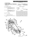
mechanism is moved with respect to the play set.Claims:
1. A play set, comprising: a planar surface; a plurality of targets
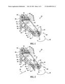
located proximate to one end of the planar surface; a feeding mechanism
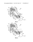
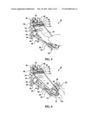
located proximate to another end of the planar surface, the feeding
mechanism being configured to launch objects at the plurality of targets
and being pivotally mounted to the play set; and a return chute
configured to receive objects from the one end of the planar surface and
return them to the feeding mechanism, the return chute having an
articulating member configured to be repositioned as the feeding
mechanism is moved with respect to the play set.
2. The play set as in claim 1, wherein the articulating member is pivotally mounted to an inlet path of the feeding mechanism at one end and a portion of the play set at another end.
3. The play set as in claim 1, wherein the feeding mechanism further comprises: an input path; an output path; an accelerating mechanism configured to receive an object from the input path and propel the object through the output path; an advancing member configured to receive an object from the input path and move it towards the accelerating mechanism; and a trigger for actuating the advancing member.
4. The play set as in claim 3, wherein the articulating member is pivotally mounted to an inlet path of the feeding mechanism at one end and a portion of the play set at another end.
5. The play set as in claim 1, wherein the planar surface and the return chute are inclined.
6. (canceled)
7. (canceled)
8. The play set as in claim 4, wherein the planar surface and the return chute are inclined.
9. The play set as in claim 1, wherein the return chute has an access opening configured to allow objects to be inserted therein.
10. The play set as in claim 1, wherein the objects are toy vehicles.
11. The play set as in claim 1, further comprising: an upper level elevated from the planar surface; and a deployable ramp configured to provide a path from the planar surface to the upper level.
12. The play set as in claim 11, wherein the articulating member is pivotally mounted to an inlet path of the feeding mechanism at one end and a portion of the play set at another end and wherein the feeding mechanism further comprises: an input path; an output path; an accelerating mechanism configured to receive an object from the input path and propel the object through the output path; an advancing member configured to receive an object from the input path and move it towards the accelerating mechanism; and a trigger for actuating the advancing member.
13. The play set as in claim 12, wherein the advancing member is a paddle rotatably mounted to the feeding mechanism.
14. A feeding mechanism for a play set, comprising: an input path; an output path; an accelerating mechanism configured to receive an object from the input path and propel the object through the output path; an advancing member configured to receive an object from the input path and move it towards the accelerating mechanism; and a trigger for actuating the advancing member.
15. The feeding mechanism as in claim 13, wherein the accelerating mechanism is a booster having at least one wheel rotated by a motor.
16. The feeding mechanism as in claim 14, wherein the object is a toy vehicle.
17. The feeding mechanism as in claim 14, wherein actuation of the trigger couples the advancing mechanism to the motor.
18. The feeding mechanism as in claim 14, wherein the advancing mechanism is a paddle rotatably mounted to the feeding mechanism.
19. A system, comprising: a track circuit, having a planar surface, a launching mechanism for launching a plurality of objects onto the planar surface and a return chute configured for receiving the plurality of objects from the planar surface and directing the received plurality of objects into the launching mechanism; a plurality of targets located proximate to the planar surface; a controller for randomly illuminating the plurality of targets and operatively coupled to the plurality of targets to determine whether one of the plurality of targets has been hit by one of the plurality of objects; and a feeding mechanism being configured to feed objects received from the return chute into the launching mechanism, wherein the launching mechanism is pivotally mounted to the track circuit.
20. A method of playing a game, comprising: launching a plurality of objects from a feeding mechanism at a plurality of targets located proximate to an end of a planar surface; returning the plurality of objects to an input end of the feeding mechanism after they have been launched at the plurality of targets; and selectively advancing one of the plurality of objects to an accelerating mechanism of the feeding mechanism after it has been received at the input end by actuating a trigger.
21. The method as in claim 20, further comprising the steps of: randomly illuminating at least one of a plurality of targets; and determining if one of the plurality of targets was hit by one of the plurality of objects when it was illuminated.
22. The method as in claim 20, further comprising the steps of: recording a score if one of the plurality of targets was hit by one of the plurality of objects when it was illuminated; and recording a final score of hit targets after a predetermined period of time.
Description:
CROSS REFERENCE TO RELATED APPLICATIONS
[0001] This application claims the benefit of U.S. Provisional Patent Application No. 61/683,959 filed Aug. 16, 2012, the contents of which are incorporated herein by reference thereto.
BACKGROUND
[0002] Play sets for toy vehicles are popular and provide entertainment and excitement to a user. These play sets typically include an extruded track configured to guide a toy vehicle, such as a 1/64 scale die-cast metal toy vehicle, through a course. The track configurations include closed-loop continuous track arrangements and open-end arrangements. Toy vehicles placed on these track sets may be propelled across the configuration by hand or by an external propulsion means.
[0003] To bring increased entertainment and excitement to play sets, track configurations may include features such as intersecting tracks, loop segments, and other types of track configurations.
[0004] Accordingly, a play set for toy vehicles that can propel toy vehicles in a unique manner is desired.
BRIEF SUMMARY OF INVENTION
[0005] In one embodiment, a play set is provided, the play set having: a planar surface; a plurality of targets located proximate to one end of the planar surface; a feeding mechanism located proximate to another end of the planar surface, the feeding mechanism being configured to launch objects at the plurality of targets and being pivotally mounted to the play set; and a return chute configured to receive objects from the end of the planar surface and return them to the feeding mechanism, the return chute having an articulating member configured to be repositioned as the feeding mechanism is moved with respect to the play set.
[0006] In another exemplary embodiment, a feeding mechanism for a play set is provided, the feeding mechanism having: an input path; an output path; an accelerating mechanism configured to receive an object from the input path and propel the object through the output path; an advancing member configured to receive an object from the input path and move it towards the accelerating mechanism; and a trigger for actuating the advancing member.
[0007] In another embodiment a system is provided, the system having: a track circuit, having a planar surface, a launching mechanism for launching a plurality of objects onto the planar surface and a return chute configured for receiving the plurality of objects from the planar surface and directing the received plurality of objects into the launching mechanism; a plurality of targets located proximate to the planar surface; a controller for randomly illuminating the plurality of targets and operatively coupled to the plurality of targets to determine whether one of the plurality of targets has been hit by one of the plurality of objects; and a feeding mechanism being configured to feed objects received from the return chute into the launching mechanism, wherein the launching mechanism is pivotally mounted to the track circuit.
[0008] In still another embodiment, a method of playing a game is provided, the method including the steps of: launching a plurality of objects from a feeding mechanism at a plurality of targets; returning the plurality of objects to an input end of the feeding mechanism after they have been launched at the plurality of targets; and selectively advancing one of the plurality of objects to an accelerating mechanism of the feeding mechanism after it has been received at the input end by actuating a trigger.
BRIEF DESCRIPTION OF THE DRAWINGS
[0009] These and/or other features, aspects, and advantages of the present invention will become better understood when the following detailed description is read with reference to the accompanying drawings in which like characters represent like parts throughout the drawings, wherein:
[0010] FIGS. 1-8 are perspective views of a play set according to an exemplary embodiment of the present invention;
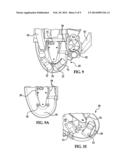
[0011] FIG. 9 is a view of a feeding mechanism of an embodiment of the present invention;
[0012] FIG. 9A is an enlarged view of the feeding mechanism in FIG. 9;
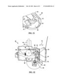
[0013] FIGS. 10 and 11 are top views of a portion of the feeding mechanism;
[0014] FIGS. 12 and 13 are bottom views of the feeding mechanism with a bottom cover removed;
[0015] FIG. 14 is bottom view of an alternative feeding mechanism with the bottom cover removed;
[0016] FIG. 15 is a perspective view of an alternative embodiment of the play set;
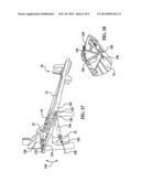
[0017] FIG. 16 illustrate features of various exemplary embodiments of the present invention;
[0018] FIG. 17 is a view along lines 17-17 of FIG. 16; and
[0019] FIG. 18 is a bottom view of a portion of the play set constructed in accordance with an exemplary embodiment of the present invention.
DETAILED DESCRIPTION OF THE INVENTION
[0020] FIG. 1 shows an exemplary play set or track set 10 for toy vehicles or objects 12 according to one non-limiting embodiment of the present invention. The play set 10 includes a planar surface 14 and a plurality of targets 16 located proximate to one end 18 of the planar surface 14. In order to launch the objects 12 onto the planar surface 14, a feeding mechanism 20 is located at another end 22 of the planar surface 14.
[0021] The feeding mechanism 20 is configured to launch the objects 12 at the plurality of targets 16. In one exemplary embodiment, the feeding mechanism 20 is pivotally mounted to the play set 10, such that movement in the direction of arrows 24 is possible. The play set 10 also has a return chute 26 configured to receive objects 12 from the planar surface 14 and return them to the feeding mechanism 20. In one embodiment, the return chute 26 has an articulating member 28 pivotally mounted to the feeding mechanism 20 at one end and an outlet chute 30 at another end. Outlet chute 30 is configured to receive objects 12 after they have passed end 18 of planar surface 14. Chute 30 receives objects 12 that pass end 18 and travel through a path 32 illustrated by the dashed lines in FIG. 1. Path 32 is located below planar surface 14 such that the vehicles or object 12 can pass edge 18 and travel onto path 32.
[0022] The pivotal mounting of the articulating member 28 allows the feeding mechanism 20 to move in the directions of arrows 24. For example, as illustrated in FIG. 2 and as the feeding mechanism 20 moves in the direction of arrows 24, a first end 36 of the return chute 26 is able to move in the direction of arrow 38, as well as in an opposite direction due to its pivotal connection to the feeding mechanism 20. Also, a second end 40 of the return chute 26 is pivotally mounted to chute 30.
[0023] In one embodiment, the feeding mechanism 20 has a pair of handles 42 for moving or pivoting the feeding mechanism in the direction of arrows 24. Return chute 26 also has an opening 44 that allows a user to insert an object or toy car 12 into chute 26 (see at least FIG. 4). Still further and to allow access to the return chute 26 and/or chute 30 an upper portion 46 of chute 30 is pivotally mounted thereto to allow a user to access an internal area of chute 30 (see at least FIG. 5).
[0024] In a similar fashion and as illustrated in at least FIG. 6, a top portion 48 of the feeding mechanism 20 is also pivotally mounted thereto such that access to an internal cavity 50 of feeding mechanism 20 is provided. A locking mechanism 51 is also provided. Locking mechanism 51 prevents inadvertent or undesired opening of top portion 48.
[0025] During game play a user starts the game wherein an accelerating mechanism or motorized booster 52 of the feeding mechanism 20 is activated. In one embodiment, the mechanism or motorized booster 52 is configured to provide a propelling force to the vehicles or objects 12 as they enter a portion of the feeding mechanism 20. The mechanism or booster 52 of the feeding mechanism 20 is located proximate to an outlet 54 of the feeding mechanism 20. Feeding mechanism 20 also has an inlet 55 configured to receive cars or objects 12 from the return chute 26.
[0026] As is known in the related arts, the motorized booster or mechanism 52 is configured to accelerate the toy vehicles 12 along surface 14 of the play set. In one non-limiting embodiment, the booster is powered by a motor 56 that is coupled to one or more booster wheels 58 that are each arranged proximate to the outlet path 54 such that an incoming vehicle 12 is propelled out of the feeding mechanism 20 via outlet path 54. The booster wheels 58 may be made of rubber (PVC), foam, or other materials known in the art. In one embodiment, a single wheel may be employed or two oppositely disposed wheels are employed. The motor 56, which may be a 6-volt electric motor or other equivalent device, rotates the booster wheels at high speeds such that vehicles or objects when introduced into the rotating booster wheels contact the rotating wheels and are propelled forward by the booster 52.
[0027] The feeding mechanism 20 is further configured to have a paddle or advancing member 70 with two distal ends. The paddle or advancing member 70 is rotatably mounted to the feeding mechanism 20 for movement in the direction of arrow 71. As illustrated in at least FIGS. 9 and 9A, paddle 70 is configured to sequentially move vehicles 12 into the booster wheels 58 of the booster 52.
[0028] Movement of paddle 70 is achieved by actuation of a trigger 72 located on one of the handles 42. In one embodiment, actuation of trigger 72 causes paddle 70 to be coupled to the motor 56 or one of the rotating booster wheels 58 such that the rotational force of the same can be imparted to paddle or advancing member 70 and thus cause the rotational movement of the paddle. As illustrated in FIGS. 10 and 11 and as the paddle rotates, vehicles 12 in area 50 are moved towards the booster wheels 58.
[0029] In one embodiment and in order to couple the paddle 70 to the motor 56 or the booster wheels 58, a shaft 74 is pivotally mounted to a base of the feeding mechanism 20. Shaft 74 is configured for movement in the direction of arrows 76, wherein a gear 78 of the shaft 74 will make intermittent contact with a worm 80 driven by motor 56 either directly or indirectly. Once gear 78 makes contact with worm 80, shaft 74 is rotated and a gear 82 coupled to shaft 74 rotates a gear 84 coupled to paddle 70. Movement of shaft 74 in the direction of arrows 76 is facilitated by movement of a linkage 86 coupled to trigger 72. As illustrated, a portion of the shaft 74 is located between a pair of features 75 such that movement of linkage 86 causes movement of shaft 74. Thus, actuation of trigger 72 causes gear 78 to contact worm or gear 80 and paddle 70 is rotated. A spring 88 causes linkage 86 and trigger 72 to be moved back to a first position, illustrated in FIG. 12, wherein gear 78 does not contact worm or gear 80.
[0030] FIG. 14 illustrates a bottom view of an alternative configuration of the feeding mechanism 20, shaft 74, worm 80 and linkage 86. Of course, numerous other configurations are contemplated wherein actuation of trigger 72 will cause the rotational movement of paddle 70 and thus advance objects or toy cars 12 towards booster 52.
[0031] Still further and referring to at least FIGS. 1-8, use of the play set is illustrated. In one embodiment, a user turns the game or play set on such that a timer is activated and the booster 52 is operational. At this point, a user can grasp the handles 42 of the feeding mechanism 20 and move it in the direction of arrows 24. Movement in the direction of arrows 24 allows a user to align outlet 55 of the feeding mechanism 20 with one of the plurality of targets 16. Once aligned, a user actuates trigger 72 and an object or toy vehicle 12 is moved into the rotating booster wheels 58 via rotational movement of the paddle 70. At this point, the vehicle 12 is launched towards the plurality of targets 16 via the rotating booster wheels 58, which are positioned such that a vehicle 12 moved into the rotating booster wheels 58 causes them to propel the object or vehicle away from outlet 55. In other words, the width of the object or vehicle 12 is slightly larger than the distance between the two rotating booster wheels 58 such that the rotating booster wheels 58 propels the object or toy vehicle 12 away from outlet 55. Afterwards, the vehicle or object 12 passes edge 18 of the surface 14 the vehicle 12 is returned to the inlet 54 of the feeding mechanism 20 via path 32, chute 30 and chute 26.
[0032] In one embodiment, the play set 10 is configured to have a controller or microcontroller 90 configured to selectively illuminate lights or LEDs or any other equivalent lighting device 91 associated with each one of the plurality of targets 16 located at the end 18 of the planar surface 14. The controller 90 is also operatively coupled to the targets 16 such that actuation of each of the targets 16 is recorded as a hit in the controller 90. In one embodiment, the hits or scores are only recorded when the targets 16 are hit when one of the associated lights are illuminated. Still further and in one embodiment, the hits or scores are recorded on a display or displays 92. In addition, the controller 90 also has a timer mechanism configured to run for a predetermined time period indicating a game period. In one embodiment, the time period may be provided on one of the displays 92. Once the time period has run, the controller 90 will end the game and no more scores or hits will be recorded.
[0033] In some alternative embodiments, once a certain time period has run, the controller 90 activates the release of a deployable ramp 98. The release of the deployable ramp 98 may make available an alternative scoring option when an object 12 travels up the deployable ramp 98. The timer mechanism may then continue to run until a full game period has elapsed, whereupon the controller 90 no longer records any additional scoring, and the display 92 provides the user with a final score. In other embodiments, once the object 12 travels up the deployable ramp 98 and activates the alternative scoring option, the game ends and the display 92 provides the user with a final score.
[0034] As illustrated, the plurality of targets 16 are spaced from each other to provide areas in which the objects 12 may miss the targets. Also shown in the attached FIGS. is that surface 14 and play set 10 is inclined so that gravity forces pull the objects 12 though path 32, chute 30 and chute 26 while the booster 52 of the feeding mechanism 20 launches them up the inclined surface.
[0035] In one non-limiting alternative embodiment and referring to at least FIGS. 1-8, the play set 10 is configured to have an upper level 96. Upper level 96 has a deployable ramp 98 that is configured to be moved from a first position (FIGS. 1-6) to a second position (FIGS. 7 and 8) wherein the ramp 98 is positioned such that an object 12 can travel onto an area 100 having a button 102. Button 102 when actuated will indicate the object 12 has moved up the ramp 98 and onto area 100 and the controller 90 coupled to the button 102 will record this event and award a predetermined amount of points, which may or may not be greater or less than the amount of points when the targets 16 are hit and the associated light 91 is illuminated.
[0036] Still referring to FIGS. 7 and 8, a game ending event indicator 104 is provided. In one embodiment, the game ending event indicator 104 is a pair of flags that are deployed upwardly when the predetermined time period of the game is over. At this point, the game stops and no further scoring is allowed.
[0037] FIG. 15 illustrates an alternative exemplary play set or track set 110 for toy vehicles or objects 12 according to one non-limiting embodiment of the present invention. The play set 110 includes an upper track segment 112, which provides an alternative path 114. Access to path 114 is provided via an entry path 116 that is partially covered by a target 118 pivotally mounted to the track set 110 such that when an object or toy vehicle 12 contacts target 118 as it travels onto upper track segment 112, a point value is registered. In one non-limiting embodiment, the point value for contacting target 118 may be higher than that of targets 16. Also, an illumination device or LED 120 may be positioned above target 118. A mentioned above, an award or points may only be provided when target 118 is hit and LED 120 is illuminated by the controller 90.
[0038] Accordingly, upper track segment 112 provides an additional feature to the play set 110. Similar to the previous embodiments, the upper track segment directs the objects or toy vehicles 12 into the return path 32, which returns the objects or toy vehicles 12 to the return chute 30. As mentioned above, the return path 32 is located below surface 14. FIG. 15 also shows an embodiment wherein a deflector or shield 122 is provided around area 100 having actuation button 102. In this embodiment, the deflector or shield 122 prevents objects from being launched past area 100 as they travel up ramp 98.
[0039] Referring now to FIGS. 16-17 yet another exemplary embodiment of the present invention is illustrated. Here the components providing return path 32 are illustrated. In this embodiment, the return path 32 of play set 10 is defined by a surface or internal plate 124 located below surface 14 such that return path 32 is provided. Surface or internal plate 124 is located such that objects or toy vehicles 12 that pass edge 18 of surface 14 after they hit or miss targets 16 land on the surface or internal plate 124 and are redirected by gravity to return chute 30 via an opening 128 in a side wall 130 of the play set 10.
[0040] In one embodiment, the play set 10 further comprises a resilient stopper mechanism 132 located behind targets 16 and edge 18. Stopper mechanism 132 is configured to stop the objects or cars 12 as they travel past edge 18. In the embodiments where cars 12 are used, the stopper mechanism 132 stops or catches the car/cars 12 and keeps them in a proper orientation until it has been stopped and no longer moves forward. Thereafter and due to the inclination of the play set 10, gravity forces will pull the cars or objects 12 back down towards return chute 30. Sequential movement of the objects or cars 12 is illustrated in at least FIGS. 16 and 17.
[0041] In one non-limiting exemplary embodiment, the stopper mechanism 132 is a foam wedge secured to an upper plate 134. In order to direct the objects or toy vehicles 12 to opening 128 and ultimately chute 30, the internal plate 124 has a wall member 136, which is configured or angled to direct the objects or toy vehicles 12 to opening 128. Accordingly, return path 32 is defined by internal plate 124, wall member 136 and a portion of side wall 130, each of which are configured to direct the vehicles to return chute 30.
[0042] In one non-limiting exemplary embodiment, the return plate 124 is pivotally mounted to the play set 10 about a pivot axis 139 for movement in the direction of arrows 138 between a first position wherein plate 124 defines return path 32 and a second position wherein external user access to return path 32 is provided. Access to return path 32 may be necessary to remove objects or toy vehicles 12 that may become jammed or stuck before they reach return chute 30. These positions are at least shown in FIGS. 16-17. In order to maintain the return plate 124 in the first position a catch or feature 140 may be employed to engage a portion of the play set 10. Feature 140 may be any one of a latch, protrusion configured to frictionally engage another portion of the play set, or any other equivalent device configured to provide releasable engagement of the return plate 124 to the play set.
[0043] FIG. 18 illustrates a bottom view of the play set 10 with an alternative configuration wherein wall 136 is secured to surface 14 and only plate 124 is pivotally mounted to the play set about a pivot axis, which in this embodiment is parallel to the wall 136.
[0044] In the preceding detailed description, numerous specific details are set forth in order to provide a thorough understanding of various embodiments of the present invention. However, those skilled in the art will understand that embodiments of the present invention may be practiced without these specific details, that the present invention is not limited to the depicted embodiments, and that the present invention may be practiced in a variety of alternative embodiments. Moreover, repeated usage of the phrase "in an embodiment" does not necessarily refer to the same embodiment, although it may. Lastly, the terms "comprising," "including," "having," and the like, as used in the present application, are intended to be synonymous unless otherwise indicated. This written description uses examples to disclose the invention, including the best mode, and to enable any person skilled in the art to practice the invention, including making and using any devices or systems. The patentable scope of the invention is defined by the claims, and may include other examples that occur to those skilled in the art. Such other examples are intended to be within the scope of the claims if they have structural elements that do not differ from the literal language of the claims, or if they include equivalent structural elements with insubstantial differences from the literal languages of the claims.
User Contributions:
Comment about this patent or add new information about this topic:
| People who visited this patent also read: | |
| Patent application number | Title |
|---|---|
| 20190051767 | PHOTOELECTRIC CONVERSION ELEMENT AND PHOTOELECTRIC CONVERSION MODULE |
| 20190051766 | PHOTOVOLTAIC GENERATION SYSTEM AND METHOD FOR USING THE SAME |
| 20190051765 | MONOLITHIC INTEGRATION TECHNIQUES FOR FABRICATING PHOTODETECTORS WITH TRANSISTORS ON SAME SUBSTRATE |
| 20190051764 | SOLAR CELL UNIT, SOLAR CELL ARRAY, SOLAR CELL MODULE AND MANUFACTURING METHOD THEREOF |
| 20190051763 | ELECTROMAGNETIC WAVE DETECTOR |

