Patent application title: ULTRASONIC DISRUPTION OF AN ANODOTIC FILM DURING ELECTROPOLISHING OF MEDICAL IMPLANTS
Inventors:
Randy Joe Myers (Bloomington, IN, US)
Assignees:
Cook Medical Technologies LLC
IPC8 Class: AC25F316FI
USPC Class:
205646
Class name: Electrolysis: processes, compositions used therein, and methods of preparing the compositions electrolytic erosion of a workpiece for shape or surface change (e.g., etching, polishing, etc.) (process and electrolyte composition) with programmed, cyclic, or time responsive control
Publication date: 2014-01-30
Patent application number: 20140027305
Abstract:
A method of electropolishing a medical implant is provided. During the
electropolishing, an anodotic film forms around surfaces of the implant.
Two or more ultrasonic transducers are oriented around the implant and
are activated to disrupt the anodotic film. The ultrasonic transducers
are activated only during a portion of the electropolishing process to
allow the anodotic film to at least partially reform.Claims:
1. A method of electropolishing a medical implant, comprising: immersing
said medical implant, an anode and a cathode in an electrolytic fluid;
contacting a surface of said implant with said anode; applying a voltage
across said anode and said cathode, said implant thereby being
electropolished and an anodotic film forming on a surface of said medical
implant; activating a first ultrasonic transducer, said first ultrasonic
transducer introducing a first wave through said electrolytic fluid and
disrupting at least a portion of said anodotic film; activating a second
ultrasonic transducer, said second ultrasonic transducer introducing a
second wave through said electrolytic fluid and disrupting at least a
portion of said anodotic film, said first and second ultrasonic
transducers being disposed at least about 45.degree. apart from each
other; and applying a voltage across said anode and said cathode after
activating said first and second ultrasonic transducers, said implant
thereby being electropolished after said anodotic film is disrupted.
2. The method according to claim 1, wherein said voltage is applied across said anode and said cathode before said first and second ultrasonic transducers are activated.
3. The method according to claim 1, wherein said cathode is disposed along a wall defining a bath of said electrolytic fluid.
4. The method according to claim 1, wherein said cathode is disposed along an entirety of said wall defining said bath.
5. The method according to claim 1, wherein said first and second ultrasonic transducers are disposed at least about 90.degree. apart from each other.
6. The method according to claim 5, wherein said first and second ultrasonic transducers are disposed more than 90.degree. apart from each other.
7. The method according to claim 1, further comprising activating a third ultrasonic transducer, said third ultrasonic transducer introducing a third wave through said electrolytic fluid and disrupting at least a portion of said anodotic film, and activating a fourth ultrasonic transducer, said fourth ultrasonic transducer introducing a fourth wave through said electrolytic fluid and disrupting at least a portion of said anodotic film, said first, second, third and fourth ultrasonic transducers being disposed at least about 90.degree. apart from each other.
8. The method according to claim 7, wherein said first, second, third and fourth ultrasonic transducers are activated sequentially, said second ultrasonic transducer being disposed at least about 120.degree. apart from said first ultrasonic transducer, said third ultrasonic transducer being disposed at least about 90.degree. apart from said second ultrasonic transducer, and said fourth ultrasonic transducer being disposed at least about 120.degree. apart from said third ultrasonic transducer.
9. The method according to claim 1, wherein said first and second ultrasonic transducers are activated at different times.
10. The method according to claim 9, wherein said first and second ultrasonic transducers are each activated for about 2 to about 60 seconds.
11. The method according to claim 10, wherein said first and second ultrasonic transducers are each activated for about 2 to about 15 seconds.
12. The method according to claim 11, wherein said first and second ultrasonic transducers are each activated for about 2 to about 5 seconds.
13. The method according to claim 9, wherein said first and second ultrasonic transducers are activated sequentially.
14. The method according to claim 13, wherein said voltage is applied across said anode and said cathode while said first and second ultrasonic transducers are activated, said implant thereby being electropolished while said anodotic film is disrupted by said first and second ultrasonic transducers.
15. The method according to claim 13, further comprising pausing said first and second ultrasonic transducers between activating said first and second ultrasonic transducers.
16. The method according to claim 15, wherein said voltage is applied across said anode and said cathode while said first and second ultrasonic transducers are paused, said implant thereby being electropolished and said anodotic film forming during said pause.
17. The method according to claim 16, wherein said pause is about 1 to about 10 seconds.
18. The method according to claim 16, wherein said pause is about 3 to about 5 seconds.
19. The method according to claim 1, wherein said first and second ultrasonic transducers are disposed at least about 90.degree. apart from each other, said first and second ultrasonic transducers are activated at different times, said first and second ultrasonic transducers are activated sequentially, and said voltage is applied across said anode and said cathode while said first and second ultrasonic transducers are activated, said implant thereby being electropolished while said anodotic film is disrupted by said first and second ultrasonic transducers.
20. The method according to claim 19, further comprising pausing said first and second ultrasonic transducers between activating said first and second ultrasonic transducers, said voltage is applied across said anode and said cathode while said first and second ultrasonic transducers are paused, said implant thereby being electropolished and said anodotic film forming during said pause, said first and second ultrasonic transducers are each activated for about 2 to about 15 seconds, and said pause is about 1 to about 10 seconds.
21. The method according to claim 20, wherein said first and second ultrasonic transducers are each activated for about 2 to about 5 seconds, and said pause is about 3 to about 5 seconds.
22. The method according to claim 21, further comprising activating a third ultrasonic transducer, said third ultrasonic transducer introducing a third wave through said electrolytic fluid and disrupting at least a portion of said anodotic film, activating a fourth ultrasonic transducer, said fourth ultrasonic transducer introducing a fourth wave through said electrolytic fluid and disrupting at least a portion of said anodotic film, and pausing said second and third ultrasonic transducers between activating said second and third ultrasonic transducers, pausing said third and fourth ultrasonic transducers between activating said third and fourth ultrasonic transducers, said voltage is applied across said anode and said cathode while said first, second, third and fourth ultrasonic transducers are paused, said implant thereby being electropolished and said anodotic film forming during said pauses, said first, second, third and fourth ultrasonic transducers are each activated for about 2 to about 5 seconds, and said pauses are about 3 to about 5 seconds, and said first, second, third and fourth ultrasonic transducers are activated sequentially, said second ultrasonic transducer being disposed at least about 120.degree. apart from said first ultrasonic transducer, said third ultrasonic transducer being disposed at least about 90.degree. apart from said second ultrasonic transducer, and said fourth ultrasonic transducer being disposed at least about 120.degree. apart from said third ultrasonic transducer.
23. The method according to claim 21, wherein said cathode is disposed along a wall defining a bath of said electrolytic fluid, and said voltage is applied across said anode and said cathode before said first, second, third and fourth ultrasonic transducers are activated.
Description:
[0001] This application claims priority to U.S. Provisional Application
No. 61/676,047, filed Jul. 26, 2012, which is hereby incorporated by
reference herein.
BACKGROUND
[0002] The present invention relates generally to medical devices and particularly to electropolishing medical implants.
[0003] Electropolishing is a widely used manufacturing process that provides a smooth surface finish to metallic parts. Typically, electropolishing is used after various forming operations, such as machining, punching, laser cutting, and electrodischarge cutting, to remove burrs, sharp edges and other rough features that are generated during the manufacture of metallic parts.
[0004] The basic concepts of electropolishing are well known to those in the art, and thus, only a brief summary is required here. Conventional electropolishing processes involve contacting a metallic part with an anode (i.e., a positively charged electrode) and spacing a cathode (i.e., a negatively charged electrode) away from the metallic part. The metallic part, along with the anode and cathode, are then immersed in a bath of electrolytic fluid. Next, a voltage is applied across the anode and the cathode for a period of time. The effect of this is that metal from the metallic part is drawn away from the metallic part and is drawn to the cathode. (Although different in some respects, electropolishing may be thought of conceptually as the opposite of electroplating.) Because burrs and sharp edges experience a higher current density than smoother surfaces on the part, metal is removed from these areas at a faster rate than the rest of the metallic part. Thus, electropolishing processes leave a smooth surface finish in which the rough edges of the metallic parts are removed.
[0005] One application in which electropolishing is particularly useful is for finishing endovascular stents and other medical implants. Medical implants require exceptionally smooth surfaces since any rough edges may cause tissue irritation during or after being implanted into a person's body. Some of the medical problems that may be encountered when rough edges are not properly removed from a medical implant include inflammation, bleeding and/or scarring of the surrounding tissues. In the case of endovascular stents, such conditions can be particularly harmful and dangerous. For example, one risk that may result from the use of stents with rough edges is restenosis. Restenosis refers to the re-narrowing of a vessel which sometimes occurs after balloon angioplasty procedures. Although restenosis may occur for a number of reasons, tissue irritation and disturbance caused by rough edges on a stent may be one cause of restenosis.
[0006] During electropolishing an anodotic film typically forms around the part being electropolished. The anodotic film may be thought of as a layer of the electrolytic fluid with a higher ionization charge level than the surrounding electrolytic fluid. Because of the higher charge level of the anodotic film, the film tends to retard electropolishing of the part's surfaces directly covered by the film. In one sense, the formation of an anodotic film during electropolishing is beneficial, since jagged, rough surfaces may be less affected by the film than large, smooth surfaces. Thus, after the anodotic film forms, electropolishing activity will diminish along the smooth surfaces of the part but continue along rough surfaces of the part. As a result, an anodotic film can serve as a helpful control on the electropolishing process.
[0007] However, due to the anodotic film's tendency to retard electropolishing, an anodotic film can interfere with improved control over electropolishing processes. In addition, the formation of an anodotic film can slow the overall electropolishing process due to its retarding of metal removal. One solution to the formation of an anodotic film could be to disturb the electrolytic fluid during electropolishing to physically break up the anodotic film. This could be done by stirring the electrolytic fluid to produce a flowing motion within the electrolytic fluid. However, this solution tends to produce inconsistent results and may not provide the level of control desired for electropolishing medical implants.
[0008] Accordingly, the inventor believes that an improved method for electropolishing medical implants would be desirable.
SUMMARY
[0009] An improved electropolishing process is described. During electropolishing an anodotic film forms around the medical implant. Ultrasonic transducers located around the implant are activated during the process to disrupt the anodotic film. The ultrasonic transducers are activated during only a part of the electropolishing process and the anodotic film is allowed to at least partially reform during the process. The inventions herein may also include any other aspect described below in the written description, the claims, or in the attached drawings and any combination thereof.
BRIEF DESCRIPTION OF SEVERAL VIEWS OF THE DRAWINGS
[0010] The invention may be more fully understood by reading the following description in conjunction with the drawings, in which:
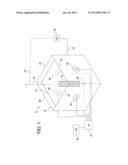
[0011] FIG. 1 is a schematic view of an electropolishing apparatus.
DETAILED DESCRIPTION
[0012] Referring now to the figures, and particularly to FIG. 1, an electropolishing apparatus 10 is shown. The electropolishing apparatus 10 includes a fluid container 12 which may be made of any suitable material capable of containing an electrolytic fluid 14. For example, the container 12 may be made from plastic or may be made from metal. However, as explained below, the apparatus 10 preferably includes ultrasonic transducers 28 to disrupt an anodotic film during electropolishing. Because plastic may interfere with the use of ultrasonic transducers 28, it is preferable that the container 12 be made from metal, and more preferably, that no plastic be present in the electrolytic fluid 14. The container 12 is filled with electrolytic fluid 14 which forms a bath 14 of electrolytic fluid 14. Preferably, the top of the container 12 is open to allow parts 16 that are to be electropolished to be lowered into and raised out of the electrolytic bath 14. Although various types of electrolytic fluid 14 may be used, a mixture of phosphoric acid and sulfuric acid may be used.
[0013] In the particular apparatus 10 shown, the part 16 to be electropolished is a stent 16, although other types of medical implants may also be used. The medical implant 16 is supported within the electrolytic bath 14 so that the medical implant 16 is preferably not touching any of the sides of the container 12. One way to support the part 16 is to hang the part 16 from a support wire 18. The electropolishing apparatus 10 is provided with a power supply 20 that provides a direct current. The positive terminal 22 is electrically connected to the stent 16 so that the stent 16 forms the anode 16 in the electropolishing circuit. This may be done by providing a separate electrical connection to the stent 16 or by connecting the positive terminal 22 to the support wire 18. The negative terminal 24 is connected to a cathode 26 immersed in the electrolytic fluid 14. The cathode 26 is a metal electrode that is spaced apart from the stent 16 so that electric current is forced to flow through the electrolytic fluid 14 between the stent 16 and the cathode 26. The cathode 26 may be a separate electrode that is suspended in the electrolytic bath between the walls of the container 12 and the stent 16. Alternatively, the container 12 may be made from metal or the container 12 may be provided with one or more plates or liners that form part of the walls 26 of the container 12. The negative terminal 24 may then be connected to the container 12 so that the entire container 12 functions as a cathode 26 or one or more walls 16 or portions thereof function as a cathode 26. This may be useful where ultrasonic transducers 28 are used as described below, since the cathode 26 will be behind the transducers 28 to provide an unimpeded path for the ultrasonic waves.
[0014] When the power supply 20 is activated, a voltage is applied across the stent 16 (anode) and container wall 26 (cathode) to electropolish the stent 16. This causes electric current and metallic particles to be drawn from the stent 16. The electric current and metallic particles pass through the electrolytic fluid 14 to the cathode 26. As the voltage is increased and/or the duration of electropolishing increases, the total amount of removed metal from the stent 16 increases. Preferably, metal is removed primarily from the corners and edges of the stent 16 so that smooth, rounded edges are formed during electropolishing. However, it may also be desirable to remove metal from the flat surfaces of the stent 16 to improve the surface finish of these surfaces as well. However, one difficulty that occurs during electropolishing is the formation of an anodotic film around the stent 16. As explained above, an anodotic film retards metal removal, and particularly affects the flat surfaces of a part 16. Once an anodotic film forms during electropolishing, increases in voltage typically have little impact on the rate of metal removal and the metal removal rate remains level over a range of voltages.
[0015] In order to disrupt the anodotic film, the electropolishing apparatus is provided with a series of ultrasonic transducers 28. Preferably, the ultrasonic transducers 28 are equally spaced around the circumference of the electrolytic bath 14 and may be mounted to the walls 26 of the container 12. Thus, where the container 12 forms a cube shape, the electropolishing apparatus 10 may have one ultrasonic transducer 28 on each side wall 26 and one ultrasonic transducer 28 on the bottom wall 26, for a total of five ultrasonic transducers 28 in the illustrated embodiment. Although it may not be necessary to have an ultrasonic transducer 28 along the top of the electrolytic bath 14, a sixth ultrasonic transducer 28 could be added at the top on a removable structure that allows access to the bath 14 or on a fixed top that provides other access around the top wall. The shape of the container 12 and number of ultrasonic transducers 28 may also be varied as desired. For example, the container 12 could be rectangular, cylindrical, etc., and the number of ultrasonic transducers 28 could include at least two transducers 28 and any practical number more than two.
[0016] The ultrasonic transducers 28 may be distributed around the container 12 in various arrangements to achieve the desired disruption of the anodotic film. However, it is preferred that ultrasonic transducers 28 oriented in different directions from each other (for example on different walls) be positioned at least 45° from each other. However, a larger angular separation may be desirable, and a 90° separation or more may provide more uniform anodotic film disruption. For example, in the apparatus 10 shown in FIG. 1, where the container 12 is a cube, each of the five ultrasonic transducers 28 may be oriented 90° from each other so that each side of the stent 16 is exposed to an ultrasonic transducer 28. As noted, the top could also be exposed to a transducer 28 with a sixth transducer 28.
[0017] The ultrasonic transducers 28 are powered and controlled by an ultrasonic generator 30 and a controller 32, such as a PLC I/O bank 32. As shown, the electropolishing apparatus 10 may be provided with a single ultrasonic generator 30, whose output is redirected to different ultrasonic transducers 28 by the controller 32. Alternatively, the apparatus 10 could be provided with separate ultrasonic generators 30 for each ultrasonic transducer 28, and the controller 32 could turn each ultrasonic generator 30 on and off as desired.
[0018] When the ultrasonic transducers 28 are activated, the transducers 28 emit and introduce an ultrasonic wave into the electrolytic fluid 14. The wave passes through the electrolytic bath 14 and will tend to disrupt the anodotic film surrounding the stent 16. However, a single ultrasonic wave that is left on continuously during the electropolishing process will tend to produce an electropolished surface that is rougher with less uniform electropolishing than desired and may produce results that are worse than if no ultrasonic transducer 28 were used. Thus, it is desirable to use more than one ultrasonic transducer 28 positioned uniformly around the stent 16. It is also desirable for the ultrasonic transducers 28 to be activated only during part of the electropolishing process so that the anodotic film is allowed to at least partially reform.
[0019] For example, the stent 16 may be electropolished for a period of time before the ultrasonic transducers 28 are activated. After an anodotic film forms around the stent 16, the ultrasonic transducers 28 may be activated together or at different times to disrupt the anodotic film. Then, after the anodotic film has been disrupted, the ultrasonic transducers 28 may be deactivated and electropolishing may be continued. It is also possible for the electropolishing to continue constantly, and the ultrasonic transducers 28 to be activated intermittently during the electropolishing process.
[0020] It is preferred for the ultrasonic transducers 28 to be activated only as long as needed to disrupt the anodotic film. The time period that each ultrasonic transducer 28 may be activated may be as short as about 2 seconds or as long as about 60 seconds. The ultrasonic transducers 28 may also be activated from about 2 seconds to about 15 seconds, or more preferred, from about 2 seconds to about 5 seconds.
[0021] The ultrasonic transducers 28 may also be activated sequentially so that the transducers 28 start and stop at different times. For example, the ultrasonic transducers 28 may be activated in a sequential pattern where the next transducer 28 that is activated is located approximately opposite from the transducer 28 preceding it. Thus, the second ultrasonic transducer 28 may be oriented at least about 120°, or 180°, from the first ultrasonic transducer 28; the third ultrasonic transducer 28 may be oriented at least about 90° from the second ultrasonic transducer 28; and the fourth ultrasonic transducer 28 may be oriented at least about 120°, or 180°, from the third ultrasonic transducer 28.
[0022] It may also be desirable to pause the ultrasonic transducers 28 between activating each of the transducers 28. This may be done while the stent 16 is being electropolished to allow the anodotic film to partially form and stabilize before each ultrasonic transducer 28 is activated to disrupt the film. For example, there may be a pause of about 1 to about 10 seconds before each ultrasonic transducer 28 is activated. There may also be a pause of about 3 to about 5 seconds before each ultrasonic transducer 28 is activated.
[0023] Thus, in a preferred example of a method of electropolishing a medical implant 16 like a stent 16, the anode 16 and cathode 26 may be charged to begin electropolishing the stent 16. Although the charge may be turned on and off during the process to start and stop electropolishing, the charge may remain continuously on throughout the process. After the stent 16 has been electropolished for a period of time and an anodotic film has formed, the ultrasonic transducers 28 may be activated to disrupt the film. However, the ultrasonic transducers 28 could be activated before the anodotic film forms to minimize formation of the film. The ultrasonic transducers 28 may be activated together or at different times. Preferably, the ultrasonic transducers 28 are activated at different times sequentially with a pause between each ultrasonic transducer 28. A sequential activation of the ultrasonic transducers 28 may be applied in a pattern around evenly spaced transducers 28 where each sequential transducer 28 is located approximately opposite from the preceding transducer 28. This may provide a uniform disruption of the anodotic film that may result in improved electropolishing of medical implants 16.
[0024] While preferred embodiments of the invention have been described, it should be understood that the invention is not so limited, and modifications may be made without departing from the invention. The scope of the invention is defined by the appended claims, and all devices that come within the meaning of the claims, either literally or by equivalence, are intended to be embraced therein. Furthermore, the advantages described above are not necessarily the only advantages of the invention, and it is not necessarily expected that all of the described advantages will be achieved with every embodiment of the invention.
User Contributions:
Comment about this patent or add new information about this topic:
Images included with this patent application:
 |  |
| Similar patent applications: | |
| Date | Title |
|---|---|
| 2014-03-20 | Electropolishing fixture with plunger mechanism |
| 2009-11-12 | Pad-assisted electropolishing |
| 2010-09-23 | X-ray assisted etching of insulators |
| 2014-03-06 | Palladium coating thickness measurement |
| 2010-01-21 | Method for coating a cooling element |
| New patent applications in this class: | |
| Date | Title |
|---|---|
| 2016-12-29 | Electrolyte and process for the electrolytic polishing of a metallic substrate |
| 2015-02-12 | Electrolytic machining system and method |
| 2013-09-19 | Process for removing a coating from workpieces |
| New patent applications from these inventors: | |
| Date | Title |
|---|---|
| 2015-04-23 | Linkage actuated hemostasis mechanism and method |
| 2013-09-26 | Hemostasis mechanism and method |
| 2011-06-23 | Biopsy needle with vacuum assist |
| 2010-07-22 | Method of electropolishing medical implants |
| 2010-02-25 | Introducer sheath having reinforced distal taper |
| Top Inventors for class "Electrolysis: processes, compositions used therein, and methods of preparing the compositions" | |
| Rank | Inventor's name |
|---|---|
| 1 | Benjamin J. Feldman |
| 2 | Adam Heller |
| 3 | Michael S. Lockard |
| 4 | Fei Mao |
| 5 | Joseph A. Vivolo |