Patent application title: Retrievable subsurface safety valve
Inventors:
John L. Garrett (Longview, TX, US)
Stan Thomas (Longview, TX, US)
IPC8 Class: AE21B3408FI
USPC Class:
166373
Class name: Wells processes operating valve, closure, or changeable restrictor in a well
Publication date: 2014-01-16
Patent application number: 20140014359
Abstract:
A multi functional assembly adaptable within a tubing string conduit to
serve as a safety valve against the possibility of a blow out. Both
surface and subsurface controllable, it offers both a partially
retrievable or totally retrievable system that allows unbiased and
unlimited work over and wire line access to an entire tubing string and
can provide safety for down hole well work. The preferred invention
comprises a housing mandrel system including closure elements
reciprocally mounted vertically within the safety valve conduit that when
unengaged provides unrestricted flow and when engaged provides
restriction amounting from limited flow to complete closure of a tubing
string. The invention provides operational options to function
hydraulically and mechanically while having the additional capability of
being remotely controlled automatically, electronically, and manually.
The hydraulic and mechanical activation systems of the safety valve can
be set to operate individually, simultaneously and selectively within the
housing mandrel conduit.Claims:
1. A safety valve having a housing with a top side and a bottom side for
controlling flow, comprising: blocking element means; means for directing
flow around said blocking element means; and, means for controlling said
blocking element means such that flow is unrestricted or restricted
through the safety valve.
2. The safety valve of claim 1, further comprising: a first conduit within the safety valve housing, wherein said first conduit runs from top side of said housing to bottom side of said housing; and, wherein the said first conduit is in communication with a lower production string attached to the said bottom side of the said safety valve housing and the upper production string attached to the top side of the said safety valve housing; and, wherein a first blocking element means positioned unengaged within said first conduit such that upward flow striking the said blocking element redirects said flow into an upper bypass conduit that is in communication with said first conduit so that upward flow is directed around said first blocking element and through said first conduit of said safety valve and into said upper tubing string; and when said first blocking element is in an engaged position within said first conduit said upward flow is restricted in said safety valve.
3. The safety valve as in claim 2, wherein said means for controlling said first blocking element means such that said flow is unrestricted or restricted through the safety valve further comprises a first elastic compression communication catch means housed within said conduit, and wherein said first catch is adapted to hold said blocking element in the said unengaged position within said conduit; and, a second elastic compression catch means is housed with the said conduit, and wherein the said second catch is adapted to halt said blocking element in the engaged position, whereas the said first catch being adaptable to provide upward support to secure said blocking element in the said engaged position.
4. A safety valve as in claim 3 wherein: said safety valve is a sub surface safety valve;
5. A safety valve as in claim 3, wherein: said first blocking element is retrievable.
6. A safety valve as in claim 3, wherein said safety valve further comprises a second conduit originating in the said safety valve housing; and, wherein said second conduit is in communication with a second upper tubing string attached to the top side of the safety valve housing; and, wherein a first lower bypass conduit is in communication with the said first conduit and the second conduit; and wherein a second blocking element is housed within the said lower second conduit; and, wherein said second blocking element has an unengaged position such that said upper flow passes through said conduit; and, an engaged position such that said flow is restricted; and, a third catch housed within the second conduit wherein the said third catch is adapted to hold said second blocking element within the said unengaged position thereby allowing said upward flow to pass through the said lower second conduit; and, a fourth catch housed within the second conduit wherein the said fourth catch is adapted to halt the said second blocking element in the engaged position thereby restricting flow within the second conduit.
7. A safety valve as in claim 6, further comprising: a plunger rod having a lower rod portion and an upper disk portion, wherein said plunger rod is housed within the said lower second conduit and said lower plunger rod portion fits into the said lower bypass conduit; and a spring is positioned between said upper disk portion of said plunger rod and said lower second conduit; and, the said second catch is adaptable to hold said plunger rod in a said unengaged position within the said lower second conduit.
8. A safety valve as in claim 7, wherein: said safety valve is a sub surface safety valve
9. A safety valve blocking element as claimed in claim 7, wherein: said second safety valve blocking element is retrievable'
10. A safety valve as in claim 7, further comprising: a third blocking element in an unengaged position within the said second conduit so that upward flow from said upper bypass conduit hitting the said third blocking element is redirected into the said first conduit; and, when lowered from above into and securely held in an engaged position restricts upward flow.
11. A safety valve as in claim 1, further comprising: a fourth blocking element; wherein said blocking element has a top side and a bottom side; and whereas said blocking element contains a vertical concentric tubular sleeve extending from said bottom side of said blocking element to said top side of said of said blocking element; and wherein said top side of said blocking element is conical containing a multitude of compression slots positioned from the top side conical opening to the bottom side of the said conical top; and, said blocking element contains a compression slot adaptable with a said conduit compression catch.
12. A safety valve as in claim 11, further comprising a blocking element catch member wherein said catch member has a top side and a bottom side; and whereas said catch contains a concentric tubular opening sleeve; and, said sleeve extends from the said top side to a centrically positioned concave conical catch adaptable to tightly contain said corresponding fourth blocking element; and, said catch means further contains a catch to engage with the said second catch with the said first conduit; and said catch has a slotted catch to engage and secure the said fourth blocking element when the said fourth blocking element is in the engaged position.
13. A preferred method utilizing embodiment 1 for controlling the flow within a subsurface well tubing string, and whereas said safety valve a disposes a hydraulic procedural operational sequence by; positioning safety valve in tubing string of well; and said first blocking element is positioned firmly in place by a first locking collar so that upward flow from tubing string after entering safety valve conduit strikes base of said blocking element; and said flow is then redirected into a conduit arrangement bypassing said blocking element in the safety valve; and, flow then is directed past said first blocking element and into top conduit of safety valve then flowing to the surface; and when flow exceeds the designated resistance limit of the first blocking element locking collar, said first blocking element is vertically released into the upward conduit flow whereas said upward flow then propels said first blocking element into the second locking collar position effectively halting said blocking element means while the said first locking collar below stabilizes the said blocking element means in place thereby cutting off all upward flow within safety valve; and whereas said first blocking element can be repositioned in original unblocked position once the well is deemed safe to reenter by a controlled downward force placed on top side of said first blocking element.
14. A fail safe method of controlling the flow within a well tubing string with a subsurface safety valve involving the mechanical procedural operational sequence by: removing the needed joints of well tubing string so that the desired safety valve depth will be attained; then, preset safety valve communication activation and halting devices; securely place the positioning tool within the upper blocking element means; place the safety valve in the tubing string; adjoin said positioning tool with above controlling means; safety valve is then prepared and ready for use at which time the tubing string is unblocked to all upward flow.
15. A method for providing safety for wireline jobs involving these steps: lower the safety valve positioning tool latch into safety valve; and then engage latch with middle blocking element to side catch and remove the safety valve middle blocking element means from the tubing string; then place the wireline safety valve latching means above the wireline blocking element means top side up on the wireline above the various installed wireline equipment; and then place the said wireline in the well with the said wireline equipment; and, endeavor to place the wireling blocking element means latch at the position so as to engage it securely with the middle blocking element engaged stopping unit; and then place the wireline blocking element means to securely seat in the middle blocking element means unengaged chamber; and begin the wireline work; then after job is complete remove the wireline equipment and wireline blocking element means and wireline blocking element means stopping latch; and then reinstall the middle blocking element means top side up within the middle blocking element means unengaged chamber; and resume normal production.
Description:
TECHNICAL FIELD OF INVENTION
[0001] This invention is related generally to safety valves, in particular to a subsurface safety valve which includes a plurality of blocking means and bypass tubes for controlling flow through tubing string.
BACKGROUND OF INVENTION
[0002] It is alarming that there is an ever growing number of wells that use no safety system whatsoever down hole. Regulatory and environmental agencies are now calling for wells to be equipped with down hole safety valves prior to completion. There are a great number of producing wells that operate with a high pressure within the tubing string. Most all of these use some sort of safety equipment with the large majority being above surface safety systems commonly referred to as "blow out preventers". While most of these units are very well built and have fairly good holding power, they still cannot offer the crucial stability that the earth provides below the surface. Furthermore, many of the more popular systems in use today are actually utilizing technology that has been in use for decades that has seen little to no effective improvement over the years.
[0003] System failures and damage to surface equipment in wells and pipelines can result in the uncontrolled release of reservoir and production fluids and hydrocarbons. These failures, often caused by the failure of faulty and unreliable safety equipment, can be the cause of all kinds of disastrous effects. Once released, foreign elements within the production flow can cause a large number of harmful effects such as deaths and injuries to humans and wildlife, destruction of natural environment, and financial loss. There are several different causes of this type of failure. First, production wells and pipeline systems operate with pressure within their tubing strings. Failure can occur when this pressure becomes too great. Second, flow itself can wear down and damage various components within the tubing string, especially when the flow contains abrasives such as sand and other harmful matter often found to exist within the tubing string. These damaged components make wells and pipelines more susceptible to failure. For these reasons, new specialized safety equipment that can effectively restrict the production flow should be used to control the flow of wells and pipelines in order to effectively address and prevent these occurrences from happening.
[0004] Safety equipment can be positioned above or below the surface. Surface units, while maintaining control of various minor fluctuations or spikes commonly occurring in production flow, may not provide the necessary level of protection needed in the event of a high pressure surface level disaster or failure. For this reason, subsurface safety equipment, widely referred to as down hole safety valves, act as a failsafe and are used to close or "shut in" producing wells in the event of such an emergency.
[0005] There are basically two types of conventional subsurface safety valves: surface controlled and subsurface controlled. As the name suggests, surface controlled safety valves are controlled from the surface, generally with an electronically operated control panel. This equipment is usually either tubing retrievable requiring a work over or wire line retrievable which may be run on a slick line or a wire line. In these surface controlled safety valves, an external control device is used to connect the safety valve to the surface control system. The major problem with surface controlled safety valves is that they require input from a source that is physically distant from the safety valve. This added complexity increases (1) the cost of the valve, (2) the cost to operate the valve, (3) the cost to operate the production well or pipeline, and more importantly (4) the likelihood of the valve's failure. Most subsurface controlled safety valves usually employ either flow or pressure sensitive devices to close the valve and most always employ complex mechanical systems. Typically, both of these type safety valves are adjoined to the tubing string so that the entire production flow is directed through them. These units can be damaged by their exposure to the flow elements within the tubing string, such as sand, paraffin, or other harmful matter within the tubing string. Over time the constant exposure to these abrasive elements contained within the production flow eventually wears down virtually all of the exposed moving parts of these valves resulting in the subsequent failure of the well or pipeline. This is especially true of the ball and flapper valves. Similarly, bellows pressure sensitive devices are also unreliable because they are susceptible to damage sustained during extreme pressure differentials. Aside from damage such as warping, fluid leakage, paraffin build up, and the like, their slow, low force movements can cause their closing valves to seat improperly. Additionally, conventional safety valves unduly restrict normal conduit flow and block access to the well bore. If flowing conditions sustain a considerable change, which is a likely event over the lifetime of a well, the preset pressure settings in these safety valves may also need to be changed. Along with any other servicing, removal, or repairs involving the safety valve, this may require a work over.
[0006] It is an object of this invention to provide a retrievable safety valve that can selectively restrict the flow of a well from a minute flow to a complete halt of flow.
[0007] It is an object of this invention to provide a subsurface safety valve that can be preset to automatically activate at a specific flow or pressure rate.
[0008] It is an object of this invention to provide a safety valve that can restrict flow in a horizontal pipeline.
[0009] It is an object of this invention to provide a safety valve that can be activated by hydraulic means.
[0010] It is an object of this invention to provide a safety valve that can be activated by mechanical means.
[0011] It is an object of this invention to provide a safety valve that can be activated electronically from a remote location.
[0012] It is an object of this invention to provide a safety valve that can be activated manually from a remote location.
[0013] It is an object of this invention to provide a safety valve that after activation can be reset without having to pull the safety valve from the well.
[0014] It is an object of this invention to provide a safety valve that is capable of having the blocking means retrieved from the well or repositioned in the well without the expense of a work over job.
[0015] It is an object of this invention to provide means of providing safety during wireline jobs.
[0016] It is an object of this invention to provide a means to help plug a non-producing well.
PRIOR ART SEARCH RESULTS
October, 2010
By a Professional Patent Search Agent at the USPTO, Alexandria, Va.
[0017] Numerous US patents of above and below ground safety devices were reviewed that were in the same field as this invention. The fields searched were as follows: 165/55. 250.08, 319-321, 338, 339. 341, 344, 345. 373, 377, 378, 379, 380, 381. Primary examiner Dang, in class 166 was consulted on this search.
[0018] The results found the following patents to be relevant, however, none exactly as disclosed.
[0019] 1. 4860826--Apparatus for sealing a tubing string in a high pressure well bore--This device is an above ground storm choke that uses a tubing piston closure device that is actuated by a pressure sensing device.
[0020] 2. 4307783--C. P. Lanmon--Method and apparatus for conducting wireline operations during blow out conditions in oil and gas wells This is an above ground system that is designed to protect wire line jobs from sudden blow outs during the down hole work.
[0021] 3. 4202368--Neil H. Akkerman--Safety valve or blow out preventer for use in a fluid transmission conduit--An above ground storm choke that uses a piston to block a preset limit of flow.
[0022] 4. 3695349 Fernando Murman--Well blow out preventer control pressure modulator Above ground bop
[0023] 5. 3561723 Edward Cugini--Stripping and blow out preventer device A rotary bop
[0024] 6. 2233077 C. P. Gillespie--Well Controlling apparatus Above ground system
[0025] 7. 5875841 Andrew Wright--Oil well blow out preventer--above ground bop device
[0026] 8. 5988274 Kelly Funk--Method of and apparatus for inserting pipes into wells has a piston like center piece with centrally placed closure plates that come together and meet to close off pipe.
[0027] 9. 6913084 Anthony Boyd--Method and apparatus for controlling well pressure while undergoing subsurface wire line operations Very complex down hole system with surface control box.
[0028] 10. 6938696 L. Murray back--pressure adapter pin and method of use Above ground bop.
DISCUSSION OF PRIOR ART
[0029] While the average cost of installing a safety valve is relatively low, the expense incurred when they need repair or servicing can be high especially in the cost of lost time and production. Most of these devices are placed within a tubing string typically allow for only a small flow passage which significantly restricts the normal conduit flow. This also is very costly. Often, access to the well bore is prohibited without removal of the safety valve and the connecting tubing string. Additionally, many of these valves must be replaced after a very short time due to the tremendous wear caused by the abrasive materials passing through the small valve openings. Many of the conventional safety valves are designed to have continuous flow passage through the exposed working parts resulting in an increased amount of wear eventually causing a breakdown of the system. Even though proponents of the conventional devices in use today claim a high degree of reliability, they can, nonetheless, be damaged by their exposure to the flow elements within the tubing. As stated above, while most of the art that is being used now has been known for decades, the subsequent improvements still have the serious drawbacks. The principal one being that of forcing the upward production to go through a virtual labyrinth of flow restricting and easily damaged components instead of simply allowing it to go around the blocking means. Not only do they significantly restrict flow, but if flowing conditions sustain a considerable change, which is likely to occur during the lifetime of a well, the preset pressure settings are likewise subject to change. These changes can go unnoticed for years causing not only lost production, but also elevating the risk of blowouts and other well damage. When these problems are made know, it may be necessary to remove the equipment from the well either to replace them or readjust the shut down settings. Whatever the reason, repairing or resetting these tools will involve a workover. This along with the lost production and the equipment costs is terribly expensive.
[0030] In addition to the drawbacks of the equipment described above, other costly problems involving some of the components of these safety valves are as follows:
[0031] The use of bellows pressure sensitive devices is unreliable due to the damage sustained during extreme pressure differentials. Aside from the damage due to warping, fluid leakage, and paraffin buildup, their slow, low force movements can cause their closing means to seat improperly.
[0032] The main problem with the ball and flapper valves is their constant exposure to the well elements. Corrosion and damaging elements such as sand, paraffin, and the like can damage the working mechanisms of these devices causing them to fail.
[0033] Most of the above and below ground safety devices have many working parts that are constantly exposed to the elements within the well. Indeed, for these devices to work properly, all of their parts must function properly. If not, then the entire system is subject to failure. Nearly all of these type down hole safety valves in use today cannot be reset down hole if they malfunction or shut off a well. Because of this, that equipment must be removed from the hole to either be replaced or reset. This requires an expensive work over job.
[0034] Blowout occurrences during wire line work are rare, but with existing down hole safety equipment the threat remains.
SUMMARY OF THE INVENTION
[0035] In accordance with the invention, the problems of safety, restricted flow, obstructed access to the well bore, unnecessary operation costs, complex mechanical systems, and necessity of work over jobs are solved with a down hole flow limiting valve with retrievable blocking elements that are not subject to the harmful elements contained of the upward production flow. While this invention provides a new and reliable means for emergency blockage of a down hole tubing string, it also provides means for selectively regulating (choking) the upward flow from a minimal flow restriction to complete blockage. It also provides means for automatically resetting the safety valve without the need for the expensive procedure of pulling the tubing string and it provides fail safe means for activating or resetting the safety valve in the event of a possible activation malfunction. All of the operational procedures can be done manually, automatically, or remotely by mechanical or electronic means. The safety valve blocking elements are tubing retrievable and can be both surface and subsurface-controlled. The system allows for blocking means to be removed, repaired, or repositioned without requiring a work over. Even with a seemingly complicated, interconnecting array of multiple blocking elements, actuating devices, resetting means, the system is, in actuality, a very simple, economical, and easy to understand device to operate. It does not necessitate a complex mechanical system for measuring flow pressures or for actuating and positioning the blocking means, as there are multiple known mechanisms that can be ideally disposed for these purposes. However, it does include an interconnected conduit system for housing multiple blocking elements with all of the moving components isolated from the upward production flow. The invention, as described below, shows known compression activation and stopping devices that are all isolated from the harmful elements within the well. As a result, all of the mechanical moving parts are less likely to be gummed up, corroded, or otherwise damaged due to sand, paraffin, and the like. Additionally, the retrievable blocking elements do not obstruct conduit flow during normal operation, but they will halt flow if the preset pressure limit is surpassed. However, if desired, they can be positioned to restrict conduit flow beyond preset pressures without altogether stopping flow. The preferred invention can be actuated mechanically, hydraulically, electronically, manually and remotely by a multitude of know means. These means can be preset to activate the safety valve in the event of an unsafe fluctuation in tubing pressure, flow speed or flow volume, or any other unsafe occurrence within the well bore. The safety valve is also adaptable as a tubing string plugging means.
[0036] The blocking elements remain unengaged in a stationary position within a conduit in the safety valve during normal operation. Once the flow exceeds a predetermined limit, one or more of the preset blocking elements can be placed in the direction of flow of the safety valve conduit before coming to rest in a position to restrict flow. As stated above, this can done automatically, but also be initiated manually from above by mechanical, electronic or other means whenever desired. Additionally, whenever desired, each engaged blocking element can be repositioned, removed, or reset in the unengaged chamber so that flow can resume. All said repositioning of the blocking elements can be achieved on a wire line by implementing the use of a preferred repositioning tool properly weighted for the type of application involved. This will insure that the positioning tool would be weighted enough to allow it to pass through the safety valve's collars in order to properly seat.
[0037] As stated above, it is not within the scope of this invention to provide new latching and catching means for the positioning of the safety valve blocking elements as there are multiple known configurations of catching and latching mechanisms that can ideally be disposed for this purpose.
[0038] Manual maneuvering of the blocking elements can be done from above in a short amount of time with little expense to the operator. Optionally, the blocking elements may be removed at any time without necessitating the removal of the safety valve itself. Although the invention may be used to particular advantage in the production well context, it can be adapted for use in virtually all types of pipelines as well. As such, this description of the preferred use should not be construed as a limitation on this disclosure. The safety valve can utilize a variety of known activation devices adaptable to propel the blocking element into the production flow conduit to halt flow. The blocking elements may be any shape capable of restricting conduit flow. In most applications, a solid cylindrical shape will effectively restrict flow in the pipeline. Simple shapes--like the solid cylinder--are more resistant to wear and damage from flow. Additionally, the said blocking element and activation arrangement as described above in some instances can be reversed with the said elastic communication means being housed within the blocking element itself.
[0039] The blocking element communication activation and stopping mechanisms described and shown herein are of the compression, spring and ball bias type, but the preferred invention is not limited to this type system as they can be of a multitude of known tubing sensing, measuring and activation devices. The preferred can additionally provide means of selectively controlling the flow within the tubing string as well. Once the blocking element enters the stream of flow, a system must be in place to stop the blocking element in a position to restrict flow. This system may be, for example, a spring-loaded device capable of retracting into the side of the conduit. The device would be preset to retract at flow rates much larger than that required to originally release the blocking element into the stream of flow. This would effectively stop the blocking element in place and restrict flow. The activation communication device can further stabilize the blocking element firmly in place from below so as to prevent it from falling into the stream of flow in case of a sudden loss of upward pressure, the When desired, the blocking element could then be pushed back into its original position and flow could resume. In the event that the operator wanted to remove the blocking element, the blocking element could be pulled through the spring-loaded retractable device at a force great enough to depress the device retractors into the side of the conduit. Once through the said retractable device, the said blocking element could be pulled out of the safety valve, up through the production string, and out of the well altogether for servicing, cleaning, or replacement.
[0040] The blocking elements may be repositioned or retrieved remotely in a variety of ways. For example, a repositioning tool can be placed in a production well that can be used to push the blocking elements back into a desired position. Similarly, the repositioning tool can be operated from above for subse locations. The repositioning tool can be attached to the top of an engaged or unengaged blocking element and used to place the blocking element into another position or to pull the blocking element completely out of the tubing string. Once the blocking means is removed from the down hole access conduit of the safety valve, the operator has complete unobstructed access to the tubing string. As stated earlier, this concept may be employed in flow line applications, such as pipelines. During normal periods of flow, the blocking means is housed unengaged within the safety valve so that it will not hinder flow or close off the well. The system can operate totally hydraulically with the middle blocking element positioned in the unengaged chamber in the down hole conduit of the safety valve. During the normal operation, production flow continues upward through the pipe string then into the lower safety valve conduit and on through the bypass-conduit arrangement as it travels to the surface. The above mentioned blocking element while unengaged is held in place by a preset communication means that is sensitive to the lower well conditions. Once the flow hitting the base of the blocking element exceeds this predetermined level, the blocking element is released from the activation communication device into the stream of flow. This added flow volume causes the said communication activation device to release the blocking element allowing it to travel upward with the flow and into an engaged blocking chamber after which it is immediately halted stopping member that is preset at a much higher setting that the said activation communication device. Once it stops, it is secured in place by the communication activation device that serves to stabilize the blocking element from falling back into the conduit if the well production flow drops.
[0041] The safety valve can also employ the opposite activation means by using a controllable preset sensitive ball and bias spring device housed within the blocking element itself. When the preset setting is surpassed, this reversed blocking element is activated. When this occurs the ball and spring device retracts from the belted slot catch of the conduit wall and into the blocking element. The latter could be more suitable in wells having frequent flow fluctuations that would cause the blocking element to make numerous movements. This type system would allow for the blocking element to be completely removed from time to time to have the activation settings changed or repaired.
[0042] The retrievable features, such as the said repositioning, resetting, and removing capabilities can be omitted allowing a much simplified embodiment of the safety valve. While this embodiment offers complete tubing string blockage involving the mechanical, electronic, manual, and hydraulic activation means as described above, this system would lack some of the above described repositioning capabilities. Of course, with this system complete removal and reinstallation involving a workover may be required whenever a blocking element assumed an engaged position. While this does not have all the capabilities of the fully equipped embodiment previously described, it might prove more cost effective on lower risk wells.
[0043] The preferred invention is also a means to provide safety while down hole work is being performed such as wire line jobs. Before the down hole job begins, the middle blocking element can be removed and replaced by a wireline blocking element system including a special wireline blocking element and an accompanying stopping cone unit that can be lowered into an unengaged position following the other wire line equipment. This system is placed above the bypass tubing arrangement. The wireline equipment passes through the safety valve while the said blocking element and cone are placed and secured within the safety valve with the said blocking element being placed and secured within the middle blocking element unengaged chamber followed by the stopping cone being placed and secured within the middle blocking element engaged chamber. The wireline which traverses through the concentric sleeves of the said stopping cone and wireline blocking element is then free to perform the wireline work. If the preset closure setting for the wireline blocking element is surpassed, then the excessive force of the upward flow will force the said blocking element to travel in the direction of the said flow and into the middle blocking element engaged chamber as it is then stopped by the wire line stopping cone. The excessive flow will also cause the male conical slots of the wireline blocking element to contract into the wireline itself as the said blocking element and female stopping cone adapt thereby shutting off the upward flow movement of the conduit. If the flow diminishes to a safe level, then the entire wire line can be removed along with all of the associated equipment.
ADVANTAGES OF THE PREFERRED INVENTION
[0044] A few of the many advantages of the preferred safety valve system are as follows:
[0045] Provides a total work through safety system;
[0046] Economical to build;
[0047] Economical to use;
[0048] Easy system for workers to understand;
[0049] Provides a means of resetting after engagement without pulling the tubing string;
[0050] Fast acting;
[0051] All activation components isolated from harmful well flow elements;
[0052] Easy to retrieve hydraulic blocking elements for servicing, replacement, and removal without pulling tubing string;
[0053] System contains no unreliable components such as flapper valves, ball valves, and the like;
[0054] Safety valve is a fail safe system with a multitude of blocking element closing options;
[0055] It can be used as a choking means as it can set to selectively restrict passage of any amount of flow;
[0056] It can be activated remotely by a multitude of means including manual, electronic, hydraulic, mechanical means.
[0057] Saving lives, property, and environment.
DESCRIPTION OF PREFERRED EMBODIMENT
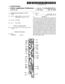
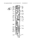
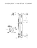
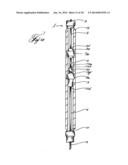
[0058] The preferred safety valve 1 may be inserted within a tubing string within the well bore casing 4 of a production well. The said safety valve 1 as shown in the following figures is herein described utilizing an arrangement of 3 blocking elements that provide a multitude of restriction levels to the upward well production ranging from a totally unengaged zero flow restriction level to a complete closure of a production flow conduit. The safety valve 1 as shown in FIG. 1 is totally unengaged with all of the blocking elements in an unengaged (stand by) position.
The Conduit System
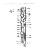
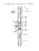
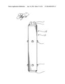
[0059] Referring to FIG. 6, the entire preferred safety valve conduit system is shown. Also shown are the blocking element activation, stabilizing, and halting units. The said combined conduit system 47 comprises 10 separate interconnected segments including (1) the down hole access bottom end conduit segment 5a, (2) the center conduit segment 5b, (3) the down hole access upper conduit segment 5c, (4) the middle conduit segment 5d, (5) the lower activation conduit segment 5e, (6) the upper blocking element conduit segment 5f, (7) the lower activation offset bypass conduit 5g, (8) the center conduit upper offset bypass conduit 5h, (9) the center conduit lower bypass conduit 5i, and (10) the lower offset bypass conduit. Also shown are the three segment conduit combinations: First are the segments 5a, 5c, and 5d together forming the down hole access conduit 46; second are the segments 5c, 5g, and 5h together forming the center bypass arrangement 6; and third is the entire safety valve conduit system 47 showing the communication of all of the said interconnected conduits. As shown, the said conduit 46 runs from the bottom 17 of the safety valve 1 to the top 16 of the safety valve 1. This conduit 46 is in vertical communication with said production tubing string 2b, coupled above and below the safety valve 1.
[0060] As shown, the said offset bypass conduit arrangement 6, provides the connection and communication combination with the said conduit segments 5a, 5c, 5e, and 5f. The lower conduit segment 5a is angularly and adjacently connected to and in communication with the lower offset by-pass conduit segment 10b which is in communication with and vertically connected with the lower conduit segment 5e center conduit which is vertically below and in communication with the center conduit segment 5b which is in communication with and angularly and adjacently connected to and in communication with the upper offset bypass conduit segment 5i. Also shown directly above the center conduit segment 5b at the angular confluence of the top bypass segment 5h is the above vertically connected service conduit segment 5f that is vertically in communication with the well bore service pipe access opening 2a that is in vertical communication with the service tubing string 2a that is extends upward to the surface platform 40.
The Hydraulic Embodiment
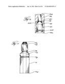
[0061] Referring to FIG. 1, the said offset bypass arrangement 6 is shown perpendicularly across from and parallel to the middle conduit segment 5d that houses the middle blocking element 11 in the middle blocking element unengaged chamber 14a. During normal operation, the formation flow is directed upwards through the production string conduit 2b, into the bottom of the safety valve conduit segment, 5a. Once in the said lower safety valve conduit segment 5a, flow continues to travel upwards where it strikes the base 11e of the middle blocking element 11. Flow is then redirected adjacently through the said offset bypass conduit arrangement 6 and on into the safety valve top conduit segment 5c as it continues upwards to the top of the safety valve 16 and into the production string 2b as it travels upwards towards the surface. The said retrievable middle blocking element means 11 while in the said middle blocking element unengaged chamber 14a does not obstruct normal flow operation. The said blocking element 11, which is also shown in FIG. 9, is held in place within the middle blocking element unengaged chamber 14a by a known elastic activation compression seating collar type arrangement comprising a blocking element belted slot 11c adaptable to engage with a known pressure sensitive protruding retractable elastic compression collar 8a projecting from the middle conduit inner wall of the safety valve middle conduit 5d. The said compression collar 8a is shown comprising known a ball 43 and bias spring 44 together adapting with conduit collar cavity 45 forming a known compression mechanism 42. While this said type compression collar 42 is shown disposed in all of the stopping and activation collars shown and described herein, the safety valve 1 is not limited to this type of device. During normal operation, the upward flow hitting the base 11e of the said blocking element 11 places an upward force on the said middle blocking element 11. As long as the flow remains below the preset failure limit the said unengaged retractable communication activation retaining device 8a effectively prevents the blocking element 11 from traveling upwards where it would halt production flow. As stated above, when the said blocking element 11 is in the unengaged position, flow is permitted to travel upwards through the bypass conduit arrangement 6, into the down hole access conduit 5c into the tubing string 2b.
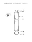
[0062] As shown in FIG. 2, once the preset limit is surpassed, the excessive flow force placed on the middle blocking element base 11e causes the said compressed spring and ball bias device 42 within the said activation collar 8a to further compress from the said blocking element belted slot 15b and into the collar cavity 45 of the said middle conduit 5d of the said middle blocking element unengaged chamber 14a thereby releasing the said middle blocking element 11 into the increased production stream of flow thus forcing the said middle blocking element 11 to hydraulically travel upward into the said down hole access conduit 5c and into the said middle blocking element engaged chamber 14b where it is immediately retained by the middle blocking element stopping collar 7a which has a much higher preset setting than the said unengaged compression activation collar 8a. Upward flow is then totally restricted as the said blocking element 11 is securely in the engaged position within the engaged chamber 14b. As also shown in FIG. 2, with the said middle blocking element 11 in the engaged position, the middle blocking element belted stabilizing slot 11d is engaged with the middle blocking element activation collar 8a. This will prevent the said blocking element 11 from falling down if there is a loss of upward flow pressure. At this point the well tubing string 2b is blocked from all flow.
[0063] This prevents blowouts, fires, and explosions on the surface of the production well because nothing can travel any further up the production string 2b.
[0064] After the well is stabilized and the operator desires to resume production, the said blocking element 11 may be either removed from the well or repositioned in the unengaged chamber 14a. In order to remove the said blocking element 11 from the well, a known latch pulling device 20b is adapted with and lowered by wireline, slick line, or the like into the safety valve 1. Once lowered into the safety valve down hole access conduit 5c, the said attached latch 20b abuts the said top side 11b of the said middle blocking element 11. Then the said positioning tool latch 20b is manipulated sideways so that it securely adapts with the middle blocking element top side catch 11a. Then the said latching device 20b is pulled upwards along with the attached said middle blocking element means 11 with enough additional force for it to pass through the said middle compression stopping collar 7a. It is then pulled to the surface so that the blocking element means 11 can be removed. Once the said blocking element 11 is removed, the operator has complete unobstructed access to the tubing string 2b.
[0065] The said engaged middle blocking element means 11 can also be returned to the unengaged position. This can be achieved by lowering the said positioning latch member 20 it into the safety valve 1 so it abuts with the said middle blocking element top side 11b and then further lowered within the said middle unengaged blocking chamber 14a as it then places a downward force upon the said unengaged blocking chamber compression activation collar 8a that is greater than the preset activation limit allowing the said blocking element means to securely seat within the said unengaged chamber 14a. Therefore the said latch 20b must be of be of sufficient weight to allow it push the said blocking element 11 through the said middle blocking element engaged activation collar 8a on its way to the said unengaged chamber 14a. When these components are in securely place within the safety valve 1 the entire conduit is open and normal flow can resume.
The Mechanical Embodiment
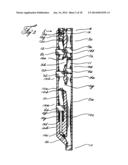
[0066] As shown in FIG. 3, the said middle blocking element 11 is housed within the middle blocking element unengaged chamber 14a of the preferred safety valve 1. During normal production flow the said middle blocking element 11 serves to divert the upward flow which is deflected by the middle blocking element base 11e as it is directed into and upwards through the bypass arrangement 6 as it travels to the surface. The figure also shows the lower compression communication collar 8b situated within the wall of the lower conduit 5e in the lower blocking element unengaged chamber 15a. The said elastic activation communication device 8b comprising of the said ball and bias spring device 42 is shown in communication with and protruding from said the collar cavity 45 of the said lower blocking element unengaged chamber 15a into the lower blocking element belted slot 10c. The said activation communication collar 8b is shown with the said ball and spring bias mechanism 42 within and in communication with the said lower blocking element activation belted slot 10c of the lower blocking element 10 which is shown within the lower blocking element unengaged chamber 15a housed within the lower conduit 5e. The said lower blocking element 10, which is shown in FIG. 8, is firmly held in place within the said unengaged chamber 15a by the preset communication activation collar 8b. The belted slot 10c surrounding the said blocking element 10 abuts the said elastic flow sensitive ball and bias spring device 42 which is in communication with the said activation collar 8b located in the inner wall of the lower conduit 5e. The lower bypass conduit 5g in communication with the adjacently adjoining safety valve down hole access bottom end conduit 5a angularly directs tubing flow force directly against the activation plunger rod base 10i which is at the terminus of the said bypass tubing conduit 5g. During normal production, the said production flow force is transferred from the said plunger rod base 10i to the belted slot 10c of the lower blocking element 10 which is in communication with and held firmly in place by the said compression collar communication device 8b which hold the said lower blocking element securely within the lower blocking element unengaged chamber 15a. The blocking elements as shown in FIGS. 8, 9, 10, and 17 all have the same belted slot configuration for activation and stabilization. While the said belted slots provide an ideal means for the purposes described herein, an alternative reversed blocking element might be desired for certain applications. As shown in FIG. 18, is a reversed blocking element with a ball and spring bias activation means 42 within the blocking element itself.
[0067] As shown in FIG. 4, when the flow force exerted on the said plunger rod base 10i exceeds the preset failure limit, the said excessive force transferred to the said protruding ball and bias spring device 42 causing the said ball 43 and bias spring 44 retract into the said collar cavity 45 of the lower communication activation collar 7b of the lower blocking element unengaged chamber 15a. This retraction movement removes the said ball 43 from the lower blocking element activation slot 10c allowing the lower blocking element activation spring 10g that is wrapped around the lower blocking element activation plunger rod 10h to instantly expand. This vertical expansion combined with the additional upward flow force causes the said plunger rod 10h to move upwards forcing the plunger rod follower disk 10j to instantly transfer the said lower blocking element 10 from the said lower blocking element engaged chamber 15a upwards into the said lower blocking element engaged chamber 15b. Once the said blocking element 10 enters the said engaged chamber 15b, it is immediately halted by the said lower blocking element engaged chamber halting collar 7b which has a much higher preset failure setting than that of the said lower blocking element activation collar 8b. The said blocking element 10 is firmly and securely stabilized within the said engaged chamber 15b by the said supporting plunger rod disk 10j which is firmly held in place by the combined upward force provided by the said activation spring 10g and upward flow emitted from said lower conduit bypass 5i. This action halts all upward flow.
Mechanical Repositioning of Lower Blocking Element
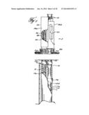
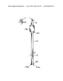
[0068] A third blocking element 12, is shown in FIG. 8. This upper blocking element 12, as shown in FIG. 1, is housed within the upper blocking element unengaged chamber 12h within the said conduit segment 5f that is vertically above and in communication with the said center conduit segment 5b and adjacently in communication with the said upper bypass conduit segment 5h. During normal operation, the said upper blocking element 12, is vertically positioned inverted within in the said upper blocking element unengaged chamber 12h within the said conduit segment 5f directly above the confluence of the said top bypass conduit segment 5h and the said center conduit segment 5b. Here the said top side of upper blocking element 12a serves to divert the normal upward flow proceeding from the center conduit 5b into the upper bypass 5f as it flows toward the surface. The said blocking element 12 is shown being held in place by a retractable compression catch 8c. This said blocking element 12 is further held in place within the said upper blocking element unengaged chamber 12h by the upper the blocking element positioning tool convex latch guide 19a of the positioning tool 18. The said latch guide 19a is shown downwardly abutting the upper blocking element concave conical base 12g. A known traversing actuator controlling mechanism 33 is shown within a housing 34 engaged with the said positioning tool 18 as it extends downward into the upper conduit segment 5f of the safety valve 1 and through the tubular opening sleeve 12b of the unengaged upper blocking element 12 terminating just beyond the upper blocking element top side 12a. Various embodiments of the said actuator 33 are commonly found on all sorts of equipment that have traversing movements such as pumps, stitching machines, elevating equipment, and the like. Likewise, the said actuator movements and powering of the said movements can be generated by a multitude of known means, with said power generating means being adapted to control the said movements. As shown, the said actuator is 33 is shown physically attached to the said positioning rod 18a which extends from the said actuator housing 33 on the well's surface side platform 40 to the top side of the said upper blocking element 12 of the safety valve 1. The said actuator 33 controls all of the traversing up and down and sideward movements of the said positioning tool 18. The said movements of the said actuator can be remotely controlled by variety of known electronic 27 and manual 37 devices. The actuators and powering choices can be made on a application type basis. The said positioning tool 18 is shown attached to the said traversing actuator 33 so that it can effectively position and reposition the said upper blocking element 12 from any position extending from the upper blocking element unengaged activation collar 8c to the lower blocking element unengaged collar 8b. The said actuator housing 34 can isolate all moving components within the actuator housing 34 from any of the harmful pressures or elements. As shown in FIG. 3, these components can also include the positioning tool actuator spring 35, the said spring propulsion base 39, and the said spring follower disk 36 all of which can be positioned within the said housing 34. The said actuator 33 being housed within the positioning tool actuator housing 34. As shown FIGS. 3 and 18 show the said positioning tool actuator 33 housed within the positioning tool actuator housing 34 positioned on the surface platform 40, the said actuator 33 can be also be configured to be housed within the safety valve 1 itself. As stated above, since the said actuator 33 generates all traversing up and down and sideward movement of the said positioning tool 18, likewise all maneuvering of the said upper blocking element 12 and latching means 20 are also controllable from above by the said actuator 33 as well. Here the said positioning tool latch means 20 is shown adapted with and forming the downward end of the said positioning tool 18 as it protrudes from the upper blocking element top side 12a of the said upper blocking element 12. The said latch 20 and said positioning tool guide 19a are shown adapted with the said positioning tool 18 in FIG. 19. The said upper blocking element 12 is shown in FIG. 1 vertically inverted within the said upper blocking element unengaged chamber 12h. As shown, the said conical latch guide 19a of the said positioning tool 18 is concentrically inserted inside the corresponding tubular opening sleeve of the upper blocking element base 12g with the said latch 20 and attached latch lifting pegs 20a within the upper blocking element top side latch lifting peg housing slots 12c. Even though at times as is shown in FIG. 1, the positioning tool latch 20 and latch pegs may protrude slightly from the top side 12a of the said upper blocking element 12, no normal upward flow will be adversely affected. The said positioning tool 18 and said latching members are used in various repositioning the lower blocking element 10 being adaptable to push and pull the said lower blocking element 10. To push the said lower blocking element 10, the said positioning tool 18 is lowered to abut and then downwardly push the top side 10b of the lower blocking element 10 into the unengaged chamber 15a or any other point between the said lower blocking element engaged chamber 15b the said unengaged chamber 15a. To pull the lower blocking element 10 upward, the said positioning tool is lowered so that the positioning tool conical guide 19a fits into the corresponding upper blocking element conical base 12g as described above. It is then perpendicularly maneuvered sideways so that the positioning tool guide notch 19b engages with the corresponding upper blocking element positioning guide slot 12h which will firmly hold the two in place so that there can be no sideward slipping between the two during the said movements. Then the positioning tool 18 is lowered to abut the top side of the lower blocking element 10b and again is perpendicularly maneuvered sideways so that the positioning tool latch lifting pegs 20a fit directly under the lower blocking element top side catch 10a so that the said pegs can engage with the said tops catch 10a to provide a lifting support to the said lower blocking element 10. The said positioning tool 18 lifts the said upper blocking element 12 into another desired position within the said safety valve 1.
[0069] In order to release the said lower blocking element 10, the said engagement procedure is reversed allowing the positioning tool to pull upper blocking element 12 upward into the said unengaged chamber 12h. As shown in FIG. 7, the said blocking element 12 can also restrict flow as it can be vertically maneuvered by the positioning tool traversing actuator 33 up and down within the upper conduit 5f and center conduit segment 5b to be selectively positioned to restrict flow as a choking means or act as a fail safe tool in the event that another blocking element means somehow failed to properly engage as it can be manually lowered into the lower blocking element engaged chamber 15b to completely halt upward production flow.
[0070] As shown in FIG. 3, the preferred safety valve is attached to and in communication with two upper strings: the positioning and service tool rod string 2a, and the down hole production flow tubing string 2b. As described, flow travels up the production string 2b. The purpose of the positioning tool rod service string 2a above the safety valve conduit segment 5f is to provide operators at the surface with access to maneuver safety valve blocking elements 10 and 12, retractable catches, spring 27, plunger rod 29, and bypass-conduits located within or convenient to the conduit segment 5e, 5b and 5f. However, the said service tubing string 2a could be converted to an additional production string if so desired. As FIG. 1 shows, some of the safety valve components, including bypass conduit segments 9a and 9b, blocking elements 10 and 11, retractable catches 8, 21, and 36, plunger rod 14, spring 15, seat 2 can be much the same and are also isolated from harmful well elements.
[0071] As shown in FIG. 5, the upper blocking element 12 is in the process of vertically repositioning an engaged lower blocking element 10 from the lower blocking element engaged chamber 15b to the lower blocking element unengaged chamber 15a. The positioning tool rod conical notched guide 19a is lowered into the upper blocking element concave conical slotted base 12g and turned so that the said notched guide 19a engages with the said upper blocking element slotted conical base 12g. After the said engagement, the said positioning tool 18 pushes the said lower blocking element 10 into the said unengaged chamber 15a so that it will engage the lower blocking element activation slot 10c with the lower blocking element activation communication collar 8b. At this point, the positioning rod can be turned so that the positioning tool latch pegs engage with the lower blocking element top side catch 10a enabling the positioning tool 18 to pull the lower blocking element 10 to another position above the lower blocking element unengaged chamber 15a. To move upward, the said positioning tool 18 is not turned to engage with the said lower blocking element catch 10a leaving the upper blocking element 12 free. Then the positioning tool 18 is then raised causing the positioning tool latch lifter pegs 20b to upwardly engage with the top side lifter peg slots 12c within the upper blocking element concentric tubular sleeve 12b of the said blocking element 12 which provides the upward movement seating support of the said upper blocking element 12 and then continues pulling the said upper blocking element 12 into the upper blocking element unengaged blocking chamber 12h and seating it with the upper blocking element activation collar 8c thereby allowing the positioning tool 18 pull the upper blocking element 12 upward into the upper blocking element unengaged chamber 12h. The safety valve 1 is then open for upward flow.
The Wire Line Embodiment
[0072] FIG. 13 shows the wireline blocking arrangement showing an unengaged wireline blocking element 13 within the middle blocking element unengaged chamber 14a of the safety valve 1 positioned to provide safety for wireline work carried on down hole within the well conduit 2b. The figure shows the slotted conical top side 13a of the said blocking element 13 with a series of parallel, hollowed out slots 13b arranged vertically within and surrounding the said concave conical top side 13a of the said blocking element 13. Also shown within the said blocking element 13 is the concentric tubular sleeve 13c that extends from the said blocking element 3 from top side 13a to bottom side 13d. This said sleeve 13c is adaptable to provide vertical traversing movement of a wireline 3 within the said sleeve. Shown in FIG. 16 is the wireline adaptable concave, conical latching means 20. The said latching means 20 which also serves to provide blockage of upward flow during the actual wireline work, is adaptable to position the said wireline blocking element 13 within the down hole access conduit 46 of the safety valve. Shown in FIG. 13 is the wireline blocking element 13 positioned within the unengaged middle blocking element unengaged chamber 14a and is adapted with the middle blocking element engaged stopping collar 7a. As stated above, the said latching means 20, so positioned, serves to provide the blockage of normal upward flow during the wireline job. However, prior to starting the wireline job, if desired for added safety, the center conduit 5b can be blocked off to further insure no passage of upward flow around the wireline blocking element. To achieve this blockage, the positioning tool rod 18a lowers the upper blocking element into the lower blocking element engaged chamber 15b and is securely held in place there by the lower blocking element engaged stopping collar 7b thus preventing any upward flow through the bypass arrangement 6. Then the said wireline blocking element 13 with the top side 13a up and wireline positioning latch 20c are inserted respectively on a wireline and lowered into the well tubing string 2b and into middle blocking element unengaged chamber 14a of the safety valve where it is securely engaged with the middle blocking element activation collar 8a. Once all of the above equipment is positioned for wireline work as stated above, the desired wireline tasks can begin. However, if during the wireline work, there is a dangerous upward flow surge that exceeds the preset limit, then the said middle activation communication unit 8a will elastically release the said blocking element 13 hydraulically into the stream of flow, as shown in FIG. 14. Even though the wireline 3 is reciprocating up and down in the well, this increased flow is sufficient to cause the communication device 8a to release the said blocking element 13 into said the stream of flow causing it to travel vertically upwards into the said middle blocking element engaged chamber 14b immediately hitting and engaging with the said wireline conical latching unit 23. When this happens, the increased upward force causes the said conical slots 13b on the top male conical side 13a of the said wireline blocking element means 13 to compress together forming a tight gripping force on the wireline 3. If needed, an o-ring can be placed in a shown grooved slot 26 for an even tighter fit. The upper belted slot 13j on the male conical top side 13a of the wireline blocking element 13 is adapted to engage with the corresponding stabilizing collar 20d of the said wireline latching unit 20c. At this point the upward flow within the safety valve down hole access conduit 46 and the well tubing string is restricted along with the traversing wireline movement thus preventing a blowout. Once it is deemed safe to continue down hole work, the surface control then can dispose the wireline 3 to pull the blocking equipment from the safety valve 1 by placing an upward pulling force greater than that of the said middle blocking element stopping collar to remove the wireline equipment and the said safety valve blocking equipment from the well. In order to resume down hole wireline work, the said safety valve wireline blocking equipment can be repositioned as described above. After the wireline job is completed, then the removed blocking element 11 can be reinserted into the safety valve 1 and reset in the unengaged chamber 14a. If the said upper blocking element 12 is in the engaged position, then the said upper conduit positioning tool 18 and attached upper blocking element 12 can be raised and then securely reposition the upper blocking element 12 within said upper blocking element unengaged chamber 12h. After these operations are completed, then upward flow can resume.
[0073] The said wireline blocking system can also be adapted to provide safety for other types of applications such as pumping units, pipelines and the like.
An Alternate Hydraulic Embodiment
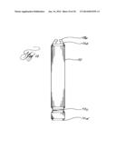
[0074] Another embodiment 9 that could be cost effective for the low risk wells is the hydraulic only arrangement as shown in FIG. 11. Shown is the preferred safety valve 1 with the bypass arrangement 6 opposite the middle blocking element unengaged housing chamber 14a. This embodiment is shown excluding the said upper and lower blocking embodiments as shown and described above. However, the blocking and repositioning operations for the middle blocking element 11 and the wireline blocking element 13 of this embodiment function the much the same way as those previously described above and as shown in the previous figures. With this system, blocking and positioning procedures of the said middle blocking element 11 and said wireline blocking element 13 can be achieved as described above. Even though some of the positioning and blocking means in other embodiments as described above are not included, this limited system 9 may be desired in low risk wells such as stripper wells and other low production wells. As shown in FIG. 12, the preferred invention can embody the above described wireline blocking system within a housing mandrel that has no bypass conduits. This unit will function exactly the same as the wireline blocking system previously described. However, this is a wireline only device that would be ideal for wireline companies to have for their own use`.
CONCLUSION
[0075] In conclusion, it is shown that the present invention and the embodiments disclosed herein and those covered by the associated claims are well adapted to carry out the objectives and ends set forth. Certain changes can be made in the subject matter without departing from the spirit and scope of this invention. It is realized that changes are possible within the scope of this invention and it is to be understood as referring to all of the equivalent elements or steps, the following claims are intended to cover the invention as broadly as legally possible in whatever form it may be utilized.
A BRIEF DESCRIPTION OF THE DRAWINGS
[0076] The drawings below show only a few of the many possible configurations of the preferred system and should not be construed to limit the scope of the invention.
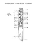
[0077] FIG. 1. Partial sectional view of the preferred safety valve unengaged.
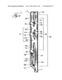
[0078] FIG. 2. Partial sectional view of the preferred safety valve with the hydraulic blocking element the engaged position.
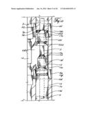
[0079] FIG. 3. Partial sectional view showing the safety valve repositioning means repositioning the lower blocking element.
[0080] FIG. 4. Partial sectional drawing of the preferred safety valve mechanical blocking element in the engaged position.
[0081] FIG. 5. Partial sectional view of positioning tool repositioning lower blocking element means.
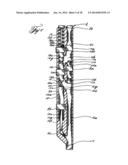
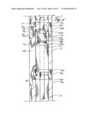
[0082] FIG. 6. Partial sectional view showing the positions of the preferred conduits, bypasses, stopping units, and activation devices.
[0083] FIG. 7. Partial sectional side view of safety valve showing the upper blocking element means in an engaged position
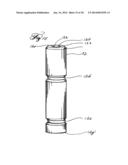
[0084] FIG. 8. Side view of the upper blocking element.
[0085] FIG. 8a. end view of the upper blocking element
[0086] FIG. 9. Side view of the middle blocking element.
[0087] FIG. 10. Side view of the lower blocking element.
[0088] FIG. 11. Partial sectional side view of the preferred safety valve with a limited bypass arrangement.
[0089] FIG. 12. Partial sectional end view of safety valve limited bypass arrangement.
[0090] FIG. 13. Partial sectional detailed side view of unengaged wire line blocking unit
[0091] FIG. 14. Partial sectional detailed side view of engaged wire line safety arrangement
[0092] FIG. 15. Isometric side view of upper blocking element.
[0093] FIG. 16. Partial sectional side view of the wireline latching unit
[0094] FIG. 17. Partial sectional side view of the wireline blocking element
[0095] FIG. 18. Partial sectional side view of safety valve
[0096] FIG. 19. partial sectional side view of upper positioning tool with latch and Guide.
User Contributions:
Comment about this patent or add new information about this topic:
| People who visited this patent also read: | |
| Patent application number | Title |
|---|---|
| 20150376758 | Method for the Hot-Dip Coating of Metal Strip, in Particular Steel Strip |
| 20150376757 | METHOD FOR DEPOSITING A CORROSION-PROTECTION COATING FROM A SUSPENSION |
| 20150376756 | LASER PATTERNING OF MULTI-LAYER STRUCTURES |
| 20150376755 | COPPER ALLOY MATERIAL FOR CONTINUOUS CASTING MOLD AND PROCESS FOR PRODUCING SAME |
| 20150376754 | METHODS FOR ARTIFICIALLY AGING ALUMINUM-ZINC-MAGNESIUM ALLOYS, AND PRODUCTS BASED ON THE SAME |
Images included with this patent application:
 |  |
 |  |
 |  |
 |  |
 |  |
 |  |
 |  |
 |  |
 |  |
 |
| Similar patent applications: | |
| Date | Title |
|---|---|
| 2014-07-10 | Method of treating ultra-low permeable subterranean formations using proppant particulates coated with degradable material |
| 2014-07-10 | Leak detection in circulated fluid systems for heating subsurface formations |
| 2014-07-10 | Method of selecting a production well location in a hydrocarbon subsurface formation |
| 2014-07-10 | Bi-directional pressure equalization valve |
| 2014-01-23 | Eccentric safety valve |
| New patent applications in this class: | |
| Date | Title |
|---|---|
| 2022-05-05 | Downhole inflow production restriction device |
| 2019-05-16 | Methods and systems for a bridge plug |
| 2017-08-17 | Sleeve fracturing assembly, device using the same and method for using the same |
| 2017-08-17 | Frac plug and methods of use |
| 2016-09-01 | Frangible plug to control flow through a completion |
| Top Inventors for class "Wells" | |
| Rank | Inventor's name |
|---|---|
| 1 | Michael L. Fripp |
| 2 | Jean Marc Lopez |
| 3 | Michael H. Johnson |
| 4 | Jørgen Hallundbaek |
| 5 | Dennis P. Nguyen |