Patent application title: Shoe rack
Inventors:
Hsiao-Hung Chiang (New Taipei, TW)
Li-Chi Chu (New Taipei, TW)
IPC8 Class: AA47B8100FI
USPC Class:
211 37
Class name: Special article shoe or boot type stands
Publication date: 2014-01-09
Patent application number: 20140008314
Abstract:
A shoe rack is provided with a stand; a plurality of elongated rack
supports secured to the stand, each of the rack supports including a
plurality of mating members on either side; and a plurality of support
assemblies each including a lower support, an upper support, a member
joining rear ends of the upper support and the lower support, and a
corresponding mating member releasably secured to the mating member.Claims:
1. A shoe rack comprising: a stand; a plurality of elongated rack
supports secured to the stand, each of the rack supports comprising a
plurality of mating members on both sides respectively; and a plurality
of support assemblies each comprising a lower support, an upper support,
a member joining rear ends of the upper support and the lower support,
and a corresponding mating member releasably secured to one of the mating
members.
2-10. (canceled)
Description:
BACKGROUND OF THE INVENTION
[0001] 1. Field of the Invention
[0002] The invention relates to shoe racks and more particularly to a shoe rack comprising rack supports each including mating members, and support assemblies each including a mating element complimentary to the mating member.
[0003] 2. Description of Related Art
[0004] Conventionally, pairs of shoes are stored in a shoe cabinet. The conventional shoe cabinet has a large storage space. Thus, the conventional shoe cabinet may occupy a large space of a room. Furthermore, internal space of the conventional shoe cabinet is divided into multiple tiers for storing shoes. However, these pairs of shoes may be different styles with different heights. The storage space of a tier is not effectively utilized if only pair of high-heeled shoes is stored therein with pairs of slippers being stored side by side in the remaining space. The conventional shoe racks also have the same drawback. Thus, the need for improvement still exists.
SUMMARY OF THE INVENTION
[0005] It is therefore one object of the invention to provide a shoe rack comprising a stand; a plurality of elongated rack supports secured to the stand, each of the rack supports comprising a plurality of mating members on either side; and a plurality of support assemblies each comprising a lower support, an upper support, a member joining rear ends of the upper support and the lower support, and a corresponding mating member releasably secured to the mating member.
[0006] The above and other objects, features and advantages of the invention will become apparent from the following detailed description taken with the accompanying drawings.
BRIEF DESCRIPTION OF THE DRAWINGS
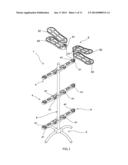
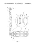
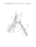
[0007] FIG. 1 is an exploded view of a shoe rack according to a first preferred embodiment of the invention with two support assemblies to be assembled;
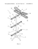
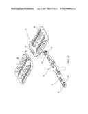
[0008] FIG. 2 is a view similar to FIG. 1 with the support assemblies being mounted on the rack support;
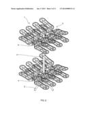
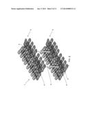
[0009] FIG. 3 is a perspective view showing two rack supports each having eight support assemblies being mounted thereon;
[0010] FIG. 4 is a longitudinal sectional view of the two support assemblies shown in FIG.
[0011] 2;
[0012] FIG. 5 is a top plan view showing the support assembly to be mounted on the rack support;
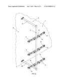
[0013] FIG. 6 is a perspective view of a shoe rack according to a second preferred embodiment of the invention with the support assemblies removed;
[0014] FIG. 7 is a view similar to FIG. 6 with the support assemblies mounted thereon;
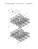
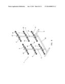
[0015] FIG. 8 is a perspective view of a shoe rack according to a third preferred embodiment of the invention with the support assemblies removed;
[0016] FIG. 9 is a view similar to FIG. 8 with the support assemblies mounted thereon;
[0017] FIG. 10 FIG. 6 is a perspective view of a shoe rack according to a second preferred embodiment of the invention with the support assemblies removed;
[0018] FIG. 11 is an exploded perspective view of a portion of a shoe rack according to a fourth preferred embodiment of the invention with the support assemblies to be mounted on the rack support; and
[0019] FIG. 12 is an exploded perspective view of a portion of a shoe rack according to a fifth preferred embodiment of the invention with the support assemblies to be mounted on the rack support.
DETAILED DESCRIPTION OF THE INVENTION
[0020] Referring to FIGS. 1 to 5, a shoe rack 1 in accordance with a first preferred embodiment of the invention comprises the following components as discussed in detail below.
[0021] A four-legged base 2 is provided. A cylindrical column 3 has a bottom end releasably secured to a center of the base 2 and extends upward. A plurality of elongated rack supports 4 are secured to the column 3 in a spaced fashion. The rack support 4 comprises a plurality of equally spaced slots 41 on either side.
[0022] A plurality of support assemblies 5 are provided. Each support assembly 5 comprises a lower support 53 substantially shaped as a sole. The lower support 53 is disposed horizontally. The support assembly 5 further comprises an upper support 52. The upper support 52 is also substantially shaped as a sole and is inclined toward its rear end (i.e., at an angle with respect to the lower support 53). The support assembly 5 further comprises a short joining member 54 joining the rear ends of the upper support 52 and the lower support 53. Thus, a space is defined between the upper support 52 and the lower support 53 for allowing one shoe 7 of a pair of shoes to be stored on a top surface of the lower support 53. Also, the other shoe 7 of the pair of shoes is stored on a top surface of the upper support 52. The support assembly 5 further comprises a matching adapter 51 on an outer surface of the joining member 54. The matching adapter 51 is adapted to insert into the slot 41 for mounting the support assembly 5 to the rack support 4.
[0023] Referring to FIGS. 6 and 7, a shoe rack 1 in accordance with a second preferred embodiment of the invention is shown. The characteristics of the second preferred embodiment are substantially the same as that of the first preferred embodiment except the following:
[0024] The shoe rack 1 is a wall mounted one. In detail, the base is eliminated. An upper bar 21 has one end secured to a wall 6 and the other end secured to a top end of the column 3. A lower bar 22 has one end secured to the wall 6 and the other end secured to a bottom end of the column 3.
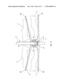
[0025] Referring to FIGS. 8 and 9, a shoe rack in accordance with a third preferred embodiment of the invention is shown. The characteristics of the third preferred embodiment are substantially the same as that of the first preferred embodiment except the following:
[0026] The base 2 is shaped as an "I" viewing from top and has an elongated rod 23 joining two short ends. There are two parallel columns 3 each having a lower end secured to the rod 23 and an open upper end. A plurality of rack supports 4 are provided along each column 3 is a spaced fashion.
[0027] Referring to FIG. 10, a shoe rack in accordance with a fourth preferred embodiment of the invention is shown. The characteristics of the fourth preferred embodiment are substantially the same as that of the first preferred embodiment except the following:
[0028] The upper support 52 and the lower support 53 are formed integrally. Each of the upper support 52 and the lower support 53 has a flat inner surface facing each other.
[0029] Referring to FIG. 11, a shoe rack in accordance with a fifth preferred embodiment of the invention is shown. The characteristics of the fifth preferred embodiment are substantially the same as that of the first preferred embodiment except the following:
[0030] The upper supports 52 are eliminated and each lower support 52 is adapted to support a pair of shoes (not shown) thereon.
[0031] While the invention has been described in terms of preferred embodiments, those skilled in the art will recognize that the invention can be practiced with modifications within the spirit and scope of the appended claims.
User Contributions:
Comment about this patent or add new information about this topic:
| People who visited this patent also read: | |
| Patent application number | Title |
|---|---|
| 20210316524 | PAPER TUBE MAKING APPARATUS |
| 20210316523 | SYSTEMS AND METHODS FOR PACKAGING INSTRUMENTS OR OTHER ITEMS WITH BAG MAKING FEATURES |
| 20210316522 | BOX AND METHOD OF CONSTRUCTING THE SAME |
| 20210316521 | Antriebsriemen, insbesondere Zahnriemen, mit verbesserten Eigenschaften und Verfahren zur Herstellung hiervon |
| 20210316520 | Ultraviolet Curing Apparatus |
Images included with this patent application:
 |  |
 |  |
 |  |
 |  |
 |  |
 |  |
| New patent applications in this class: | |
| Date | Title |
|---|---|
| 2014-10-30 | Shelf for boots storage |
| 2010-08-05 | Space-saving, themed footwear storage rack |
| 2009-08-27 | Shoe rack |
| 2009-07-02 | Shoe rack |
| Top Inventors for class "Supports: racks" | |
| Rank | Inventor's name |
|---|---|
| 1 | Stephen N. Hardy |
| 2 | Wen-Tsan Wang |
| 3 | Gregory M. Bird |
| 4 | Shane Obitts |
| 5 | Kaveh Didehvar |