Patent application title: UMBRELLA
Inventors:
Che-Hao Chen (Kaohsiung City, TW)
IPC8 Class: AA45B2502FI
USPC Class:
135 254
Class name: Umbrella collapsible in length handle or stick
Publication date: 2013-12-19
Patent application number: 20130333735
Abstract:
An umbrella includes a runner slidably mounted on a central shaft to
spread and collapse rib-and-stretcher units to which a canopy is mounted.
Each rib-and-stretcher unit includes a support rib, a stretcher, and an
extension rib. When the runner is moved from an upper position to an
uppermost position, each extension rib is driven to slide outwardly
relative to a corresponding support rib via a pivot connection between a
corresponding stretcher and the extension rib, and a main portion of the
canopy is moved together with the extension ribs to outwardly draw a
central portion of the canopy, which movably surrounds the central shaft,
to partially cover each support rib.Claims:
1. An umbrella comprising: a central shaft extending in an axial
direction; a hub unit mounted to an end of said central shaft; a runner
surrounding said central shaft and movable relative to said central shaft
in the axial direction between an upper position and a lower position; a
plurality of angularly spaced-apart rib-and-stretcher units surrounding
said central shaft, each of said rib-and-stretcher units including a
support rib that has a first end pivotally connected to said central
shaft at a position adjacent to said hub unit and a second end opposite
to said first end, an extension rib that has a proximate end slidably
connected to said support rib adjacent to said second end of said support
rib, and a distal end that is opposite to said proximate end; and a
stretcher that has a first end pivotally connected to said runner and a
second end opposite to said first end of said stretcher and pivotally
connected to said proximate end of said extension rib, a canopy mounted
on said rib-and-stretcher units and including a main portion, that covers
said support ribs and said extension ribs and that is connected fixedly
to said distal end of said extension rib of each of said
rib-and-stretcher units, and a central portion that interconnects said
main portion of said canopy and said hub unit and that surrounds movably
said central shaft; wherein, when said runner is moved from the lower
position to the upper position, said support rib and said extension rib
of each of said rib-and-stretcher units are driven to spread relative to
said central shaft via the pivot connections among said central shaft,
said runner and said rib-and-stretcher units; and wherein, when said
runner is further moved along said central shaft from the upper position
toward said end of said central shaft to an uppermost position, said
extension rib of each of said rib-and-stretcher units is driven to slide
outwardly relative to said support rib of a corresponding one of said
rib-and-stretcher units via the pivot connection between said stretcher
of the corresponding one of said rib-and-stretcher units and said
proximate end of said extension rib, and said main portion of said canopy
is moved together with said extension ribs to draw said central portion
outwardly to partially cover said support ribs; and a positioning
mechanism disposed on said central shaft for positioning said support
ribs relative to said central shaft during movement of said runner
between the upper and uppermost positions.
2. The umbrella as claimed in claim 1, wherein said hub unit includes: a housing mounted fixedly to said end of said central shaft and receiving a portion of said central shaft therein; an abutment member disposed in said housing, connected fixedly to said central portion of said canopy, and slidable relative to said portion of said central shaft in the axial direction; and a biasing member disposed in said housing and connected to said abutment member for biasing said abutment member toward said end of said central shaft.
3. The umbrella as claimed in claim 2, wherein said housing includes a main wall mounted to said end of said central shaft and a ring-shaped wall connected to a bottom end of said main wall, said portion of said central shaft extending through said ring-shaped wall into said housing, and said biasing member having opposite ends that abut respectively against said abutment member and said ring-shaped wall.
4. The umbrella as claimed in claim 3, wherein said biasing member is a compression spring.
5. The umbrella as claimed in claim 2, wherein said housing includes a main wall receiving said portion of said central shaft and having a top wall section that is mounted to said end of said central shaft, said biasing member having opposite ends that are connected respectively to said abutment member and said top wall section.
6. The umbrella as claimed in claim 5, wherein said biasing member is an extension spring.
7. The umbrella as claimed in claim 1, further comprising a handle and a telescopic shaft unit interconnecting said handle and an opposite end of said central shaft that is opposite to said end of said central shaft in the axial direction so that a distance between said handle and said central shaft is adjustable.
Description:
CROSS-REFERENCE TO RELATED APPLICATION
[0001] This application claims priority of Taiwanese Patent-Application No. 101211312, filed on Jun. 13, 2012, the disclosure of which is herein incorporated by reference.
BACKGROUND OF THE INVENTION
[0002] 1. Field of the Invention
[0003] This invention relates to an umbrella, more particularly to an umbrella including a canopy that has an adjustable coverage area.
[0004] 2. Description of the Related Art
[0005] A conventional umbrella includes a central shaft, a runner surrounding the central shaft and movable between upper and lower positions, and a plurality of angularly spaced-apart. rib-and-stretcher units mounted with a canopy and drivable by the runner to spread and collapse together with the canopy and relative to the central shaft. However, coverage area of the canopy of the conventional, umbrella is usually fixed, and cannot be changed. Therefore, while a large coverage area is obtained through a relatively large canopy, the portability the conventional umbrella is adversely affected. Alternatively, a foldable umbrella, which has a foldable canopy and foldable rib-and-stretcher units, is relatively portable, but the coverage area of its canopy is relatively small.
SUMMARY OF THE INVENTION
[0006] The object of the present invention is to provide an umbrella including a canopy that has an adjustable coverage area.
[0007] According to this invention, the umbrella comprises a central shaft, a hub unit, a runner, a plurality of angularly spaced-apart rib-and-stretcher units, a canopy, and a positioning mechanism. The central shaft extends in an axial direction. The hub unit is mounted to an end of the central shaft. The runner surrounds the central shaft and is movable relative to the central shaft in the axial direction between upper and lower positions. The rib-and-stretcher units surround the central shaft. Each of the rib-and-stretcher units includes a support rib having a first end that is pivotally connected to the central shaft at a position adjacent to the hub unit and a second end that is opposite to the first end, an extension rib having a proximate end that is slidably connected to the support rib adjacent to the second end of the support rib and a distal end that is opposite to the proximate end, and a stretcher having a first end that is pivotally connected to the runner and a second end that is opposite to the first end of the stretcher and that is pivotally connected to the proximate end of the extension rib. The canopy is mounted on the rib-and-stretcher units and includes a main portion and a central portion. The main portion covers the support ribs and the extension ribs and is connected fixedly to the distal end of the extension rib of each of the rib-and-stretcher units. The central portion interconnects the main portion of the canopy and the hub unit and movably surrounds the central shaft. When the runner is moved from the lower position to the upper position, the support rib and the extension rib of each of the rib-and-stretcher units are driven to spread relative to the central shaft via the pivot connection among the central shaft, the runner and the rib-and-stretcher units. When the runner is further moved along the central shaft from the upper position toward the end of the central shaft to an uppermost position, the extension rib of each of the rib-and-stretcher units is driven to slide outwardly relative to the support rib of a corresponding one of the rib-and-stretcher units via the pivot connection between the stretcher of the corresponding one of the rib-and-stretcher units and the proximate end of the extension rib, and the main portion of the canopy is moved together with the extension ribs to draw the central portion outwardly to partially cover the support ribs. The positioning mechanism is disposed over the support ribs for positioning the support ribs relative to the central shaft during movement of the runner between the upper and uppermost positions.
BRIEF DESCRIPTION OF THE DRAWINGS
[0008] Other features and advantages of the present invention will become apparent in the following detailed description of the preferred embodiment of the invention, with reference to the accompanying drawings, in which:
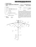
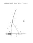
[0009] FIG. 1 is a partly sectional view of a preferred embodiment of an umbrella according to the invention;
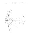
[0010] FIG. 2 is a fragmentary perspective sectional view of the preferred embodiment, illustrating a hub unit of the umbrella;
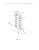
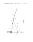
[0011] FIG. 3 is a fragmentary partly sectional view of the preferred embodiment, illustrating a runner of the umbrella at an upper position;
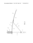
[0012] FIG. 4 is a schematic partly sectional view of the preferred embodiment, illustrating the runner moved upwardly;
[0013] FIG. 5 is a schematic partly sectional view of the preferred embodiment, illustrating the runner at an uppermost position;
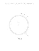
[0014] FIG. 6 is a schematic top view of the preferred embodiment, illustrating a canopy of the umbrella having an adjustable coverage area;
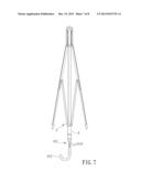
[0015] FIG. 7 is a partly sectional view of the preferred embodiment, illustrating the runner being at a lower position; and
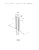
[0016] FIG. 8 is a fragmentary perspective sectional view to illustrate a modification of the hub unit.
DETAILED DESCRIPTION OF THE PREFERRED EMBODIMENT
[0017] Referring to FIG. 1, the preferred embodiment of an umbrella according to the present invention comprises a central shaft 2, a runner 3, a plurality of angularly spaced-apart rib-and-stretcher units 4, a hub unit 5, a canopy 6, and a positioning mechanism 7.
[0018] The central shaft 2 extends in an axial direction (X). The runner 3 surrounds the central shaft 2 and is movable relative to the central shaft 2 in the axial direction (X) between an upper position (FIG. 1) and a lower position (FIG. 7).
[0019] The rib-and-stretcher units 4 surround the central shaft 2. Each of the rib-and-stretcher units 4 includes a support rib 41 that has a first end 411 pivotally connected to the central shaft 2 at a position adjacent to the hub unit 5 and a second end 412 opposite to the first end 411, an extension rib 42 that has a proximate end 421 slidably connected to the support rib 41 adjacent to the second end 412 of the support rib 41 and a distal end 422 opposite to the proximate end 421, and a stretcher 43 that has first end 431 pivotally connected to the runner 3 and a second end 432 opposite to the first end 431 of the stretcher 43 and pivotally connected to the proximate end 421 of the extension rib 42.
[0020] When the runner 3 is moved from the lower position to the upper position, the support rib 41 and the extension rib 42 of each of the rib-and-stretcher units 4 are driven to spread relative to the central shaft 2 via the pivot connection among the central shaft 2, the runner 3, and the rib-and-stretcher units 4.
[0021] Further referring to FIG. 2, the hub unit 5 includes a housing 51, an abutment member 52, and a biasing member 53. The housing 51 receives a portion of the central shaft 2 therein and includes a main wall 511 mounted fixedly to an end 20 of the central shaft 2 and a ring-shaped wall 512 connected to a bottom end 513 of the main wall 511. The portion of the central shaft 2 extends through the ring-shaped wall 512 into the housing 51. The abutment member 52 is disposed in the housing 51 to surround the portion of the central shaft 2 and is slidable relative to the portion of the central shaft 2 in the axial direction (X). The biasing member 53 is disposed in the housing 51 and has opposite ends that are connected respectively to the abutment member 52 and the ring-shaped wall 512 so as to bias the abutment member 52 toward the end 20 of the central shaft 2. In this embodiment, the biasing member is a compression spring.
[0022] The canopy 6 is mounted on the rib-and-stretcher units 4 and includes a central portion 61 and a main portion 62. The main portion 62 covers the support ribs 41 and the extension ribs 42 and is connected fixedly to the distal end 422 of the extension rib 42 of each of the rib-and-stretcher units 4. The central portion 61 interconnects the main portion 62 of the canopy 6 and the abutment member 52 of the hub unit 5 and movably surrounds the portion of the central shaft 2. In this embodiment, the canopy 6 is made of elastic fabrics.
[0023] The positioning mechanism 7 is disposed over the support ribs 4 at a position adjacent to the hub unit 5 for positioning the support ribs 41 relative to the central shaft 2 after the runner 3 moves from the lower position to the upper position. In this embodiment, the ring-shaped wall 512 of the housing 51 of the hub unit 5 is configured to serve as the positioning mechanism 7 for prohibiting pivot movement of the supporting ribs 41 relative to the central shaft 2 during the movement of the runner 3 from the upper position to the uppermost position. The configuration of the positioning mechanism 7 may vary in other embodiments of this invention as long as it is able to position the supporting ribs 41.
[0024] Referring to FIGS. 3 to 5, when the runner 3 is further moved from the upper position (FIG. 3) toward the end 20 of the central shaft 2 to the uppermost position (FIG. 5), since the support ribs 41 are not pivotable relative to the central shaft 2 due to the positioning mechanism 7, the extension rib 42 of each of the rib-and-stretcher units 4 is driven to slide outwardly relative to the support rib 41 of a corresponding one of the rib-and-stretcher units 4 via the pivot connection between the stretcher 43 of the corresponding one of the rib-and-stretcher units 4 and the proximate end 421 of the extension rib 42, countering a resilient force of the biasing member 53. At the same time, the main portion 62 of the canopy 6 is moved together with the extension ribs 42 to draw the central portion 61 of the canopy 6 outwardly to partially cover the support ribs 41. Thus, the coverage area of the umbrella can be adjusted by simply moving the runner 3 between the upper position and the uppermost position.
[0025] Preferably, a positioning device (not shown) is provided to position the runner 3 relative to the central shaft 2 at a selected position between the upper and uppermost positions. The coverage area of the umbrella, indicated by A, B, and C in FIG. 6, is adjusted when the runner 3 moves between the upper and uppermost positions. When the runner 3 is at the uppermost position, the support ribs 41 and the extension ribs 42 are covered by the main portion 62 and the exposed portion of the central portion 61 of the canopy 6, which represents the largest coverage area (C) of the umbrella. When the runner 3 is moved to the selected position, the coverage area (B) of the umbrella is smaller than the coverage area (C). Finally, when the runner is moved from the selected position to the upper position, the portion of the central portion 61 is automatically drawn back into the housing 51 by a restoring force of the biasing member 53, which leads to a normal coverage area (A) that is smaller than the coverage area (B).
[0026] It should be noted that, referring back, to FIG. 1, the umbrella further comprises a handle 212 and a telescopic shaft unit 211 interconnecting the handle 212 and an opposite end of the central shaft 2 that is opposite to the end 20 of the central shaft 2 in the axial direction (X) such that a distance between the handle 212 and the central shaft 2 can be adjusted as desired.
[0027] In this embodiment, the telescopic shaft unit 211 includes a plurality of telescopically interconnected segments 2110. Referring further to FIG. 7, when the runner 3 is at the lower position, the segments 2110 of the telescopic shaft unit 211 can be retracted from an expanded state (see FIG. 1) into the central shaft 2 to provide a compact total size of the umbrella.
[0028] Referring to FIG. 3, a modification of the hub unit 5 is shown. The housing 51 includes a main wall 511 receiving the portion of the central shaft 2 and having a top wall section 5110 that is mounted to the end 20 of the central shaft 2. The biasing member 53 is configured as an extension spring and has opposite ends that are connected respectively to the abutment member 52 and the top wall section 5110.
[0029] While the present invention has been described in connection with what is considered the most practical and preferred embodiment, it is understood that this invention is not limited to the disclosed embodiment but is intended to cover various arrangements included within the spirit and scope of the broadest interpretations and equivalent arrangements.
User Contributions:
Comment about this patent or add new information about this topic:
Images included with this patent application:
 |  |
 |  |
 |  |
 |  |
 |
| New patent applications in this class: | |
| Date | Title |
|---|---|
| 2013-04-11 | Handheld or attachable visor |
| 2010-02-11 | Portable and compact umbrella |
| Top Inventors for class "Tent, canopy, umbrella, or cane" | |
| Rank | Inventor's name |
|---|---|
| 1 | Oliver Joen-An Ma |
| 2 | Mark C. Carter |
| 3 | Wanda Ying Li |
| 4 | Wanda Ying Li |
| 5 | Kendyl A. Roman |