Patent application title: Mouthpiece
Inventors:
Kazuhiko Shimizu (Kobe-Shi, JP)
IPC8 Class: AA24F702FI
USPC Class:
131223
Class name: Tobacco users' appliance device used for smoking with valve or external passage closure
Publication date: 2013-12-19
Patent application number: 20130333709
Abstract:
A non-combustion smoking tool, which uses a real filter cigarette as it
is, and which vaporizes nicotine from the tobacco leaves without lighting
the product to enable inhalation of the vaporized nicotine, has a problem
that a smoker cannot take in 100% of the vaporized nicotine. Thus, a
mouthpiece is designed to have an air flow control structure or an air
flow control element, or to be combined with a cigarette guide tube, so
as to enable the mouthpiece to vary the rate at which the nicotine
vaporized from the tobacco leaves is taken in.Claims:
1. A mouthpiece used in combination with a non-combustion smoking tool
which uses a real filter cigarette as it is, and uses a heating heater to
vaporize nicotine contained in tobacco leaves thereof to enable
inhalation of the nicotine, wherein the mouthpiece comprises an air flow
control structure or an air flow control element to allow the rate at
which the filter absorbs the vaporized nicotine to be varied between zero
and an arbitrary rate.
2. The mouthpiece according to claim 1, wherein the air flow control structure or the air flow control element comprises a structure which can hold a fragrance or a material containing water.
3. The mouthpiece according to claim 1, which is used in combination with a cigarette guide tube to fit the mouthpiece.
4. The mouthpiece according to claim 3, further comprising a spacer inserted therein which has a diameter substantially equal to that of the filter cigarette and which serves to make an adjustment to the length substantially equal to that of the filter cigarette so as to enable a filterless cigarette, a cigar or tobacco leaves to be put in the cigarette guide tube for use, wherein the spacer can be designed to hold a fragrance or a material containing water.
5. The mouthpiece according to claim 1, which is used in combination with the non-combustion smoking tool having an outline shape of a pipe.
6. The mouthpiece according to claim 1, which is used in combination with a drive circuit with a built-in heater which has mounted thereon a circuit for generating a voltage waveform from an input voltage and a set temperature (which can be switch input) on printed circuit boards placed to hold a sleeve part of the heater.
Description:
TECHNICAL FIELD
[0001] The present invention relates to a mouthpiece provided for non-combustion smoking tools and used in combination with a non-combustion smoking tool of Japanese Patent Application 2009-049879 or Japanese Patent Application 2009-293338 made by the present applicant (each hereinafter referred to as "tool--of the earlier application of the present application"), a non-combustion cigarette system disclosed in Japanese Translation of PCT Application 2009-509521 or a pipe-type non-combustion smoking tool.
BACKGROUND ART
[0002] The "tool of the earlier application of the present application" and the non-combustion smoking tools disclosed in Patent Document 3and Patent Document 4 have been proposed to improve various problems of a normal smoking method to light tobacco leaves for smoking, and are tools which, while using a generally commercially available cigarette or cigar as it is, can vaporize nicotine from the tobacco leaves at a suitable temperature to enable inhalation without burning the tobacco leaves, making it possible to inhale it.
PRIOR ART DOCUMENT(S)
Patent Document(s)
[0003] Patent Document 1: Japanese Patent Application 2009-049879
[0004] Patent Document 2: Japanese Patent Application 2009-293338
[0005] Patent Document 3: Japanese Translation of PCT Application 2009-509521
[0006] Patent Document 4: Japanese Laid-open Patent Publication Hei 6-114105
SUMMARY OF THE INVENTION
Problem(s) to be Solved by the Invention
[0007] When the tool of the earlier application of the present application and the non-combustion smoking tool proposed in Patent Document 3 were actually used by inserting a filter cigarette therein, the following problems were found.
[0008] By heating the tobacco leaves with a heater, nicotine is vaporized from the tobacco leaves. However, when inhaled through the filter similarly as when normally smoking by lighting them, most of the nicotine vaporized out of the tobacco leaves by heating the tobacco leaves is absorbed by the filter, so that a smoker can inhale only a small amount of nicotine vaporized out of the tobacco leaves.
[0009] Further, when the smoker wants to take in more nicotine, it is necessary to increase the heating temperature, for example about to 200° C. to 240° C., so as to increase the vaporization speed of nicotine from the tobacco leaves. However, when heated at such a high temperature, the tobacco leaves get burned to add burning smell, thereby not only harming the flavor, but also ending the vaporization of nicotine from the tobacco leaves in a short time.
[0010] In the non-combustion smoking tool proposed in Patent Document 4, a filter cigarette is heated from the outside by a cylindrical heater. Thus, upon actual inhalation, the paper of the filter cigarette is first heated to vaporize harmful substances from the wrapping paper, so that a mixture of the harmful substances and nicotine vaporized from the tobacco leaves is supplied to the smoker.
[0011] In addition, according to the non-combustion smoking tool proposed in Patent Document 4, a problem has been found that upon continuous inhalation, most of hot air heated by the cylindrical heater passes through the space between the inner surface of the cylindrical heater and the outer surface of the inserted cigarette because the air resistance in the tobacco leaves is high, causing only the hot air to be brought to the mouth of the smoker without heating the inserted tobacco leaves.
Means to Solve the Problem(s)
[0012] According to the present invention, a mouthpiece having a novel structure has been conceived to solve the above problems which are caused when the tool of the earlier application of the present application described above or the non-combustion smoking tool proposed in Patent Document 3 is used for a filter cigarette.
[0013] Further, a mouthpiece has been conceived, such that in the mouthpiece having the novel structure, a hole is formed on the surface of the air flow control structure or the air control element which contacts the filter so as to produce an air flow through the filter, allowing the filter to absorb a part of produced nicotine.
[0014] Further, it has been found that the combination of a cigarette guide tube with the mouthpiece having the novel structure makes it easier to make a non-combustion smoking tool, and provides an easy-to-use mouthpiece with an attached cigarette guide tube.
Effect of the Invention
[0015] FIG. 3 shows a cross-sectional view of an example of a mouthpiece used as a mouthpiece having a novel structure adopted in the present invention. In the mouthpiece having the novel structure, an air flow control element is formed between an inhalation inlet and a filter of an inserted filter cigarette. If the air flow control element has no through-hole, air passing through the filter part cannot directly reach the inhalation inlet when a smoker inhales through the mouthpiece. Thus, when the smoker inhales, nicotine vaporized from the tobacco leaves by heating the tobacco leaves goes out of the wrapping paper of the tobacco, and passes through a space formed between an inner wall of a non-combustion smoking tool and the wrapping paper of the tobacco and the filter, and further passes through the air control element so as to be brought to the inhalation inlet. This is advantageous because, due to the air flow containing the nicotine, the nicotine vaporized from the tobacco leaves is prevented from being absorbed by the filter, so that the smoker can inhale most of the nicotine vaporized from the tobacco leaves.
[0016] Further, it is advantageous to form a hole on the filter-contacting surface of the air control element of the mouthpiece having the novel structure adopted in the present invention, because it produces an air flow flowing through the filter, making it possible to allow the filter to absorb an appropriate amount of nicotine vaporized from the tobacco leaves, and thus to allow the smoker to inhale the vaporized nicotine with a desired concentration.
[0017] Further, FIG. 8, FIG. 13 and FIG. 14 show cross-sectional views of other examples of mouthpieces having the novel structure adopted in the present invention, in which each of them has an advantage that the rate at which the filter absorbs the produced nicotine can be controlled between zero and an arbitrary rate.
[0018] Further, the combination of a cigarette guide tube with these mouthpieces having the novel structure is advantageous because it provides easy-to-use mouthpieces with an attached cigarette guide tube.
[0019] Further, in the mouthpiece having the novel structure adopted in the present invention and provided with the attached cigarette guide tube, it is advantageous to bend an end of the cigarette guide tube inward because the mouthpiece with the attached cigarette guide tube can be taken out of the non-combustion smoking tool together with the inserted filter cigarette.
BRIEF DESCRIPTION OF THE DRAWING(S)
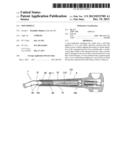
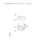
[0020] FIG. 1 is an appearance view when a filter cigarette set in a mouthpiece of EXAMPLE 1 of the present application is about to be inserted into the tool of the earlier application of the present application.
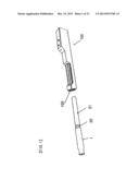
[0021] FIG. 2 is a cross-sectional view of the tool of the earlier application of the present application.
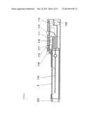
[0022] FIG. 3 is a cross-sectional view of the mouthpiece of EXAMPLE 1 of the present application.
[0023] FIG. 4 is an appearance view of an example of an air flow control element of the mouthpiece of EXAMPLE 1 of the present application.
[0024] FIG. 5 is an appearance view of another example of an air flow control element of the mouthpiece of EXAMPLE 1 of the present application.
[0025] FIG. 6 is a cross-sectional view when the filter cigarette set in the mouthpiece of EXAMPLE 1 of the present application is inserted into the tool of the earlier application of the present application.
[0026] FIG. 7 is an appearance view of a mouthpiece and an appearance view of an air flow control element of EXAMPLE 2 of the present application.
[0027] FIG. 8 is a cross-sectional view of the mouthpiece of EXAMPLE 2 of the present application.
[0028] FIG. 9 is an appearance view of the air flow control element used in the mouthpiece of EXAMPLE 2 of the present application.
[0029] FIG. 10 is an appearance view of an air flow control element used in the mouthpiece of EXAMPLE 2 of the present application.
[0030] FIG. 11 is an appearance view of a mouthpiece of EXAMPLE 3 of the present application.
[0031] FIG. 12 is a side view of the mouthpiece of EXAMPLE 3 of the present application.
[0032] FIG. 13 is a cross-sectional view of the mouthpiece of EXAMPLE 3 of the present application.
[0033] FIG. 14 is a cross-sectional view of a mouthpiece of EXAMPLE 4 of the present application.
[0034] FIG. 15 is an appearance view when a filter cigarette set in a mouthpiece of EXAMPLE 4 of the present application is about to be inserted into a pipe-type non-combustion smoking tool.
[0035] FIG. 16 is a cross-sectional view when the filter cigarette inserted into the mouthpiece of EXAMPLE 4 of the present application is inserted into the pipe-type non-combustion smoking tool.
[0036] FIG. 17 is a cross-sectional view when a filter cigarette inserted into the mouthpiece of EXAMPLE 3 of the present application is inserted into a pipe-type non-combustion smoking tool.
[0037] FIG. 18 is a cross-sectional view when the filter cigarette is set in the mouthpiece of EXAMPLE 3 of the present application, and a cigarette guide tube is set therein.
[0038] FIG. 19 is a view where a cigarette guide tube A is inserted in FIG. 18 to reduce space between the cigarette part and the cigarette guide tube.
[0039] FIG. 20 is a cross-sectional view of a mouthpiece with an attached cigarette guide tube formed by setting the cigarette guide tube in the mouthpiece of EXAMPLE 2 of the present application and placing a spacer therein.
[0040] FIG. 21 is a cross-sectional view when a filter mouthpiece is set in the mouthpiece of EXAMPLE 2 of the present application, and a shortened cigarette guide tube is set therein.
[0041] FIG. 22 is a cross-sectional view when a filter cigarette set in the mouthpiece of EXAMPLE 4 of the present application and having a cigarette guide tube attached thereto is set into the pipe-type non-combustion smoking tool.
[0042] FIG. 23 is a cross-sectional view of a heating heater and an electronic circuit used in the pipe-type non-combustion smoking tool shown in FIG. 17.
[0043] FIG. 24 is an appearance view of the heating heater shown in FIG. 23.
[0044] FIG. 25 is an example of a mechanism to make variable the area of a hole to determine the rate at which the filter absorbs nicotine.
DESCRIPTION OF THE EMBODIMENTS
[0045] Hereinafter, detailed description will be made with reference to the drawings, giving a commercially available filter cigarette as an example for the present invention.
[0046] Before the description, the background where the present invention was made will be described. The present inventor developed non-combustion smoking tools and conducted monitoring experiments. However, the opinion of the monitors did not seem to be that they could take in nicotine. When the heating temperature was increased to about 200 to 240° C., their only feeling was that initially they could take in nicotine a little, but even that disappeared in a few minutes.
[0047] Thus, for the effect of filters of normal commercially available filter cigarettes, the present inventor has used commercially available "MILD SEVEN 10" and a gas chromatography mass spectrometer (TG-GC/MS) to perform measurements of the amount of nicotine taken in, depending on the presence or absence of a filter, according to a normal smoking method to light them. It has been found that based on 15.463 mg in the case of the absence of a filter and 0.775 mg in the case of the presence of a filter, 95% of nicotine produced is in fact absorbed by a filter. In other words, it has been found that even when the tool of the earlier application of the present application is used to vaporize nicotine from the inserted tobacco leaves, the nicotine produced passes through the filter to cause about 95% thereof to be absorbed by the filter and only about 5% thereof to be supplied to the smoker. Thus, it has been found that the reason why the monitors of the tool of the earlier application of the present application do not feel taking in nicotine is the nicotine absorption effect of the filter.
[0048] A normal smoking method to light tobacco leaves for smoking bums tobacco leaves or a wrapping paper, thereby producing much harmful substances to a human body such as tar and carbon monoxide in addition to nicotine. Thus, a filter is required to prevent these harmful substances from being taken in the body. However, it has been found that in the tool of the earlier application of the present application or the non-combustion smoking tool as disclosed in Patent Document 3, which hardly produces such harmful substances and produces only pure nicotine, a filter only serves to extremely reduce the amount of the produced nicotine which is taken in.
[0049] Considering these occurring, the tool of the earlier application of the present application is designed to be usable even if the filter of the filter cigarette is removed.
[0050] However, although a filter may be unnecessary, it is laborious to smoke after removing the filter when using a non-combustion smoking tool. The present application has been conceived to enable a smoker to sufficiently take in nicotine produced by heating tobacco leaves when a non-combustion smoking tool is used with a filter cigarette as it is.
[0051] Various structures of the mouthpieces according to the present invention will be described in detail with the drawings in EXAMPLES 1, 2, 3 and 4. Their structures and features will be described sequentially below, but these are used to describe the present invention concretely, and the present invention is not limited by these as long as the subject matter described in the patent claims is embodied.
EXAMPLE 1
[0052] FIG. 3 shows a cross-sectional view of a mouthpiece of EXAMPLE 1 of the present application. The mouthpiece 1 comprises an inhalation inlet 2, an air flow control element 3 and a filter housing part 4. As shown in FIG. 4, the air flow control element 3 comprises a combination of two components 31 and 34. The outer diameter of the component 31 is designed to be substantially the same as the inner diameter of the filter housing part 4. The outer diameter of the component 34 is designed to be substantially equal to or smaller than the outer diameter of the component 31, and equal to or larger than the diameter of an axial hole 32. The mouthpiece 1 has an outer diameter designed to tightly fit an insertion opening 103 of the non-combustion smoking tool shown in FIGS. 1 and 2 so as to prevent air leakage.
[0053] FIG. 5 shows an appearance view of another example of an air control component 3. This air control component 3 has a shape similar to a normal gear, and comprises six gear teeth 37 and an axial hole 38. The outer diameter of the gear teeth 37 is made substantially equal to the inner diameter of the filter housing part 4. It is needless to say that the number of gear teeth is not limited to six as shown, but can be an arbitrary number as a usable one.
[0054] FIG. 1 is a view immediately before a commercially available filter cigarette (filter part 20 and cigarette part 21) set in the mouthpiece 1 shown in FIG. 3 is inserted into an insertion opening 103 of a tool 100 of the earlier application of the present application. FIG. 2 is a cross-sectional view of the tool 100 of the earlier application of the present application shown in FIG. 1. This tool comprises a printed circuit board 111 with a built-in electronic circuit, a heater 110, a thermal insulation material 9 and a plastic case. Mounted on the printed circuit board 111 are a connector 112, a switch 113, a preset variable resistor 115, a microcomputer 116 for reading their set values to control the amount of heating power to the heater 110, an output transistor 117 for supplying power to the heater, an LED 118 for displaying an operational state of this circuit, and other electronic components. A DC voltage (3 to 12 V) is supplied to this circuit through the connector from a battery, a rechargeable battery, an AC adapter, a DC power supply, a car cigarette power supply, or the like. 103 is an insertion opening, while 105 is an air inlet. FIG. 7 and FIG. 8 of Patent Document 2 describes in detail a specific circuit diagram and voltage waveforms applied to a heater.
[0055] FIG. 6 is a cross-sectional view when the filter cigarette set in the mouthpiece shown in FIG. 3 is inserted into the tool 100 of the earlier application of the present application.
[0056] First, FIG. 6 is used to describe the case where a hole 35 of FIG. 4 or an axial hole 38 of FIG. 5 is not present. A cigarette part 21 of the filter cigarette allows the heater 110 in the non-combustion smoking tool 100 to be inserted therein, and is heated by the heater or preheated by a linear part of the heater. Since the end surface of the filter part 21 is covered with the air flow control element 3, nicotine vaporized from the tobacco leaves by the hot air heated by the coil part of the heater upon inhalation by a smoker cannot pass through the filter part 21, and thus passes through the wrapping paper to go out of the wrapping paper and pass through a space between an inner surface of the thermal insulation material 9 and the wrapping paper. The nicotine then passes through a space between an inner surface of the mouthpiece 1 and an outer surface of the filter part 20, which in the case of FIG. 4 further passes through the axial hole 32 via windows 33 of the air flow control element 3 so as to be brought to the mouth of the smoker through the inhalation inlet 2, and which in the case of FIG. 5 further passes through the gear teeth 37 of an air flow control element 36 so as to be brought into the mouth of the smoker through the inhalation inlet 2.
[0057] Thus, it has been found that the nicotine vaporized and extracted from the inserted tobacco leaves is not absorbed by the filter of the filter cigarette, and substantially 100% of the produced nicotine is brought into the mouth of the smoker.
[0058] Next, the case where the hole 35 of FIG. 4 and the axial hole 38 of FIG. 5 are present will be described. A cigarette part 21 of the filter cigarette allows the slender heater 110 in the non-combustion smoking tool 100 to be inserted therein, and is heated by the heater or preheated by the linear part of the heater. Nicotine vaporized from the tobacco leaves by the hot air heated by the coil part of the heater upon inhalation by a smoker passes through the wrapping paper from a central portion to go out of the wrapping paper and pass through the space between the inner surface of the thermal insulation material 9 and the wrapping paper. The nicotine then passes through a space between the inner surface of the mouthpiece 1 and the wrapping paper of the filter, and further passes through the axial hole 32 via the windows 33 of the air flow control element 3 so as to be brought to the mouth of the smoker through the inhalation inlet 2, or alternatively passes through the gear teeth 37 of the air flow control element 36 so as to be brought to the mouth of the smoker through the inhalation inlet 2. If the hole 35 and the axial hole 38 are present, a part of the nicotine vaporized from the tobacco leaves can pass through the hole 35 or the axial hole 38 through the cigarette part 21 and through the filter part 20, thus producing a flow of nicotine, as well, that reaches the mouth of the smoker while a part of the nicotine is absorbed by the filter.
[0059] In this case, it has been found that it is possible to control the amount of air flow through this path by changing the hole diameter of the hole 35 and the axial hole 38, consequently making it possible to control the amount of the produced nicotine which is absorbed by the filter.
[0060] More specifically, it has been found that by varying the hole diameter of the hole 35 and the axial hole 38 between zero and substantially the outer diameter of the filter, the rate at which the filter absorbs the nicotine vaporized and extracted by heating the tobacco leaves can be varied between zero and the intrinsic absorption rate of the filter, which is very effective because the smoker can smoke with a desired concentration.
[0061] Here, it is needless to say that the shapes of the windows 33 and the gear teeth 37 are not limited to those shown, and can have any size and shape if they have a function to allow air to flow.
EXAMPLE 2
[0062] FIG. 7 shows an appearance view of a mouthpiece of EXAMPLE 2 of the present application. FIG. 8 is an A-A' cross-sectional view of FIG. 7. This mouthpiece comprises a mouthpiece outer case, an air flow control element 3-1 and a filter housing part 4.
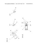
[0063] As shown in FIG. 7 and FIG. 8, the mouthpiece 1 has two slits 6. The slits 6 serve to guide produced nicotine to the inhalation inlet 2, and facilitate insertion into the non-combustion smoking tool or facilitate insertion of a cigarette guide tube 10 by allowing the outer diameter of the mouthpiece 1 to be virtually reduced when the mouthpiece 1 is pressed from outside upon insertion into the non-combustion smoking tool or upon insertion of the cigarette guide tube 10 into the mouthpiece 1 as described later. Although FIG. 7 describes the case of two, the same effect can be obtained with three or more.
[0064] Further, the slits have length L1 which is designed to be longer than insertion length L2 of the filter cigarette in the mouthpiece 1 as shown in FIG. 8. For inserting the filter cigarette set in the mouthpiece into the non-combustion smoking tool, the entire length of the slits 6 is required to be inserted into the tool through the insertion opening 103. In addition, the mouthpiece 1 is required to have an outer diameter to tightly fit the insertion opening 103 to prevent air leakage.
[0065] The air flow control element 3-1 has four holes 7 (which can be any number) and a rod 8 for positioning the insertion position of the inserted filter cigarette. The rod 8 has a function to position the insertion position of the inserted filter cigarette. Further, the rod 8 has another function. Similarly as in the hole 35 shown in FIG. 4 and the axial hole 38 shown in FIG. 5, the rate at which the filter 20 absorbs a part of the nicotine extracted from the tobacco leaves can be varied by varying the hole diameter of the rod 8. FIG. 7 shows another air flow control element 3-2. This example designs a rod 8 with a larger end portion. If the diameter of this end portion is made substantially equal to the diameter of the filter cigarette, substantially 100% of nicotine produced by heating the inserted cigarette is brought to the mouth of the smoker without being absorbed by the filter part. By making the diameter of the end portion of the rod 8 smaller than the diameter of the filter part, the produced nicotine can be absorbed by the filter at an arbitrary rate.
[0066] The air flow control elements 3, 3-1, 3-2 have been described above as separate elements. However, when making the mouthpiece 1, it is easy to make mouthpiece molds to produce similar effects. Thus, it is needless to say that they can be made either as separate elements to be combined with the mouthpiece, or made integrally with the mouthpiece.
[0067] Further, the present inventor has made the air flow control elements 3, 3-1, 3-2 described above and so on, and has conducted experiments. If the hole 35 or the hole 38 is not present, or if the rod 8 is substantially equal in diameter to the filter, it has been found that substantially 100% of nicotine vaporized from the cigarette part 21 enters the mouth of the smoker when the smoker inserts the filter cigarette to allow the front end of the filter of the filter cigarette to tightly contact these elements, while when the filter cigarette is not inserted to tightly contact these elements, a part of nicotine vaporized from the cigarette part 21 is absorbed by the filter part 20.
[0068] It has been found that the cause of this is that the bottom surface of the filter part 20 does not intimately contact the air flow control element, which produces, between the air flow control element and the bottom surface of the filter part 20, a gap forming a path of air flow from the cigarette part 21 through the filter part 20, so that when the smoker inhales, a part of vaporized nicotine rides on the air flow to pass through the filter part 20, causing the nicotine contained in the air flow to be absorbed by the filter part 20.
[0069] Thus, as shown in an appearance view of FIG. 10, the present inventor has improved the rod 8 of the air flow control element 3-2 to a rod 81. The rod 81 is a cylinder designed to have a depth of at least 2 mm and at most substantially the length of the filter part 20 for housing the filter part 20. The cylinder has either no or at least one hole 97 at a bottom thereof (FIG. 10 shows two).
[0070] It has been found that if the hole 97 is not present, the use of the rod 81 substantially prevents air flow through the filter part as long as the front end of the filter is inserted in the cylinder of the rod 81 even if the filter cigarette is roughly inserted into the rod, allowing substantially 100% of produced nicotine to be brought to the mouth of the smoker.
[0071] Further, it has been found that if the hole 97 is present, air flow to pass through the filter part is produced, enabling a part of produced nicotine to be absorbed by the filter, and in addition, the rate at which the filter part absorbs the nicotine can be varied by varying the hole diameter of the hole 97.
EXAMPLE 3
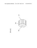
[0072] FIG. 11 is an appearance view of a novel mouthpiece 1 of EXAMPLE 3 of the present application. FIG. 12 is a right side view of FIG. 11. This mouthpiece is an embodiment of the subject matter of the present invention based on the structure of the mouthpiece instead of the air flow control element. The mouthpiece 1 comprises four parts, in which 93 is a filter housing part, and has a portion to fit a part 92 as shown in a cross-sectional view of FIG. 13. This portion is rotated by a smoker for use so that a groove 94 is rotated to match one of holes 95-1, 2, 3. A hole 97 is formed in a central wall of the filter housing part 93. As shown in the cross-sectional view of FIG. 13, the part 92 is designed to fit a part 91 as well, and has the holes 95-1, 2, 3. A right side of the part 92 is a cover which has two holes 99 of different sizes. When the part 93 is rotated to allow the groove 94 to match the hole 95-1, a hole 99 with a diameter substantially equal to the hole 97 is positioned facing the hole 97. When the groove 94 is allowed to match the hole 95-2, a hole 99 formed with a diameter of about half that of the hole 97 is positioned facing the hole 97. When the groove 94 is allowed to match the hole 95-3, no hole 99 is positioned facing the hole 97. The smoker can rotate the part 93 to allow the groove 94 to match one of the holes 95-1, 2, 3 so as to change the rate at which the filter absorbs nicotine. Further, it is advantageous to use, for the part 92, a resin different in color from the part 91 because, while a filter cigarette set in the mouthpiece needs to be inserted beyond the part 92 when inserted into the non-combustion smoking tool, the color change allows the smoker to know at a glance how far it should be inserted. In addition, there is an advantage that, while the cigarette guide tube 10 needs to be inserted beyond the part 92 when the above is used in combination with the cigarette guide tube 10 as described later, the color change allows the smoker to know at a glance how far it should be inserted.
[0073] The parts 93, 91, 90 are preferably made from a little flexible resin material such as polypropylene and silicone resin. By making the parts 93, 91, 90 from flexible polypropylene, silicone resin or the like, it becomes easy for the insertion opening 103 to fit the part 91 when the filter cigarette set in the mouthpiece is inserted into the non-combustion smoking tool, and it becomes also easy for the cigarette guide tube, when set, to fit the mouthpiece, and in addition, it gives a pleasant mouth feel when the smoker inserts the mouthpiece 1 into the mouth.
[0074] The part 91 is designed to fit the part 92. Further, as shown, the part 91 is made to increase slightly in diameter toward the mouth. Thus, when the filter cigarette set in the mouthpiece is inserted into the non-combustion smoking tool 100 or 101, the insertion opening 103, even with variations in diameter, fits the mouthpiece with no gap at an appropriate position upon insertion. Further, also when the cigarette guide tube 10 described later is attached to the mouthpiece, the cigarette guide tube 10, even with variations in inner diameter, can fit the mouthpiece with no gap at an appropriate position upon insertion. However, if the insertion opening 103 and the inner diameter of the cigarette guide tube 10 are accurately made, it is not necessary that the diameter of the part 91 increases slightly in diameter toward the mouth.
[0075] In the outside of the mouthpiece 1 shown in FIG. 11, the groove 94 with a depth smaller than the wall thickness of the filter housing part 93 is formed as shown, and has an end connected at the part 92 to hollows 96 by the holes 95-1, 2, 3. Further, slits 98 are formed in the filter housing part 93. The slits 98 facilitate insertion of the cigarette guide tube 10 when the filter housing part 93 is pressed by fingers to virtually reduce the diameter upon insertion of the cigarette guide tube 10 into the mouthpiece 1 as described later.
EXAMPLE 4
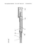
[0076] FIG. 14 is a mouthpiece of EXAMPLE 4 of the present application. This novel mouthpiece is also an embodiment of the subject matter of the present invention as obtained by changing the structure. A first difference is that the filter housing part 93 has been changed to a tube 93-1. The tube 93-1 is, for example, like a straw made of polypropylene, and is formed to just fit the projecting portion of the part 92, while 4 is a filter housing part. The tube 93-1 has an outer diameter smaller than the outer diameter of the fat portion of the part 92. A cover or bottom is formed on the projecting portion (on the filter side) of the part 92. The hole 97 to change the rate at which the filter absorbs nicotine is formed in this cover or bottom. Holes 95 are formed with the part 92 and the tube 93-1 combined and fit together.
[0077] Once formed, the area of the windows 33 of FIG. 3(SIC FIG. 4), or the area between the gear teeth of FIG. 4(SIC FIG. 5), or the diameter of the holes 7 of FIG. 7, or the diameter of the holes 95 of FIG. 13 described above cannot be changed by the smoker. Thus, if the smoker wants to change the amount of air flow when smoking, these components themselves have to be changed. In contrast, EXAMPLE 4 as shown in FIG. 14 is highly advantageous because the holes 95 are formed with the part 92 and the tube 93-1 combined and fit together, so that the smoker can allow the holes 95 to have an arbitrary opening area by slightly rotating the tube 93-1 after the smoker combines the tube 93-1 and the part 92 (the amount of air flow then being determined by the diameter of the holes 95), making it possible for the smoker to smoke with a desired amount of air. A second difference is that the part 90 and the part 91 are not straight and have an angle. This is advantageous because if this angle is about 5 degrees to 50 degrees, the bending allows the non-combustion smoking tool to be positioned below eye level when the smoker uses the mouthpiece and the non-combustion smoking tool, thus enabling the smoker to smoke comfortably, and also allows the outline shape of the pipe-type non-combustion smoking tool 101 to much resemble a real pipe. Note that this angle can either be provided between the part 91 and the part 90, or can be formed by bending a portion of the part 92, to obtain the same effect.
[0078] FIG. 15 is an appearance view immediately before a filter cigarette set in the mouthpiece 1 shown in FIG. 14 is inserted into a pipe-type non-combustion smoking tool 101. It has a part 102 which corresponds to where tobacco leaves would be placed in the case of a normal pipe, and which is a display part for displaying various information by guiding light from a light emitting diode 118 which is driven by a drive circuit to blink. Alternatively, it can be designed to detect inhalation (by a detector not shown) upon smoking/inhalation, allowing it to light red as if upon smoking/inhalation by normal lighting.
[0079] FIG. 16 is an axial cross-sectional view where a filter cigarette set in the mouthpiece 1 shown in FIG. 14 is inserted into the pipe-type non-combustion smoking tool 101. When inserted into the non-combustion smoking tool 101, a cigarette part 21 is heated by the heating heater 110 or by high temperature air produced by the coil part to vaporize nicotine. If the hole 97 is not present, the vaporized nicotine goes out of the wrapping paper of the tobacco and passes through a space formed between the outside of the wrapping paper and the inside of the insulation material 9 or the inside of the non-combustion smoking tool 101, and then passes through a space formed between the tube 93-1 and the inside of the non-combustion smoking tool 101, and further passes through the holes 95 and through the hollows 96, allowing substantially 100% of the produced nicotine to be brought to the mouth of the smoker. The insertion opening 103 and the part 91 of the mouthpiece are formed to tightly fit together to prevent air leakage.
[0080] Further, if the hole 97 is present, the vaporized nicotine is partially absorbed by the filter when the smoker inhales because it is brought to the mouth of the smoker through the filter part 20 and through the hole 97. Consequently, the rate at which the filter absorbs produced nicotine is changed by the hole diameter of the hole 97, making it possible for the smoker to inhale nicotine with a desired concentration.
[0081] FIG. 17 is an axial cross-sectional view where a filter cigarette set in the mouthpiece 1 shown in FIG. 13 is inserted into the non-combustion smoking tool 101. It is different from FIG. 16 in that it has an angle of 5 degrees to 50 degrees at the neck of the pipe while the part 90 and the part 91 of the mouthpiece 1 are straight through. Thus, the heater 110 is bent at the same angle. In addition, the heater has no coil part, and, needless to say, can be similarly bent even if it has a coil part.
[0082] It has been found from experiment results that ease of insertion and ease of use are facilitated, if the inner diameter size of the filter housing part 4 of FIG. 3, FIG. 8, FIG. 11 and FIG. 14 and of the rod 81 of FIG. 10, which are specific drawings according to the present invention described above, is finished to the outer diameter of the inserted filter plus 0.01 mm to 1.0 mm. Besides, their depth is designed to be at least 2 mm and at most about the same as the length of the inserted filter part.
[0083] Further, the axial hole 32 of the air flow control element 3 of FIG. 4, the axial hole 38 of FIG. 5, the air flow control elements 3-1, 3-2 of FIG. 7 and the parts 92 of FIGS. 13, 14 can be drilled inside to create a space for housing various fragrances to produce a tobacco flavor, a menthol flavor, a mint flavor, a lemon flavor and so on, or materials to produce water. FIG. 9 shows that the rod 8 of the air flow control element 3-1 is drilled inside to create a space 12. The axial hole 32 of FIG. 4 and the axial hole 38 of FIG. 5 can be used as spaces for placing these. This is advantageous because by placing fragrances and materials to produce water in these spaces, a smoker can smoke more comfortably since the flavors of these fragrances and water in addition to nicotine vaporized from the tobacco leaves enter the mouth of the smoker upon smoking using a non-combustion smoking tool.
[0084] Further, the hole 35 of FIG. 4, the axial hole 38 of FIG. 5, the diameter of the rod 8 of FIG. 8, the hole 97 of FIG. 13 and the hole 97 of FIG. 14 have a function to determine the rate at which the filter absorbs nicotine upon smoking. Normally, the mouthpiece 1 is made as a molded product of plastic or the like. If the wall thickness of the molded product is made small, and the internal components with them are colored or made of colored materials, it is easy to make the mouthpiece 1 so that the colors of the components, when inserted therein, can be recognized from outside. If this is used to make three kinds of them different in nicotine absorption rate, large, medium and small absorption rates, that are made e.g. of pink, orange and red colors, then the smoker can see from the outside which one of the air flow control elements with a certain nicotine absorption rate is placed in the mouthpiece 1, so that the smoker can easily understand it.
[0085] Further, it has been found from experiment results that the total area of the windows 33 of FIG. 4, the total area between the gear teeth of FIG. 5, the total hole area of the holes 7 and the area of the hole diameter of the hole 95 of FIG. 13 or FIG. 14 exert a significant influence when the smoker smokes. If the hole diameter is too small, a strong inhalation force is required when smoking. If it is too large, a problem arises in that the speed of inhalation by the smoker exceeds the speed of vaporization of nicotine when the tobacco leaves are heated by the heater, causing the speed of vaporization of nicotine to be insufficient. It has been found from experiment results that the total area or the area of the total hole diameter is preferably 0.01 square mm to 12 square mm.
[0086] Further, the smoker can change the rate at which the filter absorbs vaporized nicotine, if a mechanism shown as an example in FIG. 25 is used instead of the air flow control element B 34 of FIG. 4, and instead of the rod 8 which is shown in the element 3-2 of FIG. 7 and which has an outer diameter substantially equal to the diameter of the filter, and instead of the cover of the part 92 of FIG. 14. More specifically, a disc A and a disc B have elongated holes 53 formed therein, and the discs A, B are designed to be rotatable about a shaft 50 as a center. When they are stopped where the two elongated holes exactly match, maximum absorption occurs in the filter. As the matching area of the two elongated holes is decreased by rotating the discs, the rate at which the filter absorbs nicotine decreases. When there is no matching area, substantially 100% of the vaporized nicotine is brought to the smoker.
[0087] Further monitoring has been conducted using the various mouthpieces according to the present invention above, and it has been found that there is another problem. The problem will be described in detail using FIG. 6. When a smoker inhales upon smoking, air enters through the air inlet 105, and passes through the section of the circuit, and then enters the thermal insulation material 9 from an opening on the right side of the thermal insulation material 9, and further goes through the space between the inner surface of the thermal insulation material 9 and the outside of the wrapping paper along with nicotine heated and vaporized by the heater 110 so as to be brought to the mouth of the smoker through the space formed between the outside of the filter part 21 and the inside of the mouthpiece 1 and through the windows 33 of the air flow control element 3. However, in order to ensure this path, it is required that the outer diameter of the mouthpiece 1 tightly fits the insertion opening 103 to a level to prevent air leakage, and that the left end portion of the thermal insulation material 9 intimately contacts an inner surface of the tool 100 to a level to prevent air leakage as well. Normally, this condition therefor cannot be achieved unless a rubber packing is placed in this position.
[0088] In the example shown in FIG. 16, when the smoker inhales upon smoking, air enters through the air inlet 105, and enters the thermal insulation material 9 from an opening on the right side of the thermal insulation material 9, and then goes through the space formed between the inner surface of the thermal insulation material 9 and the outside of the wrapping paper along with nicotine heated and vaporized by the heater 110 so as to be brought to the mouth of the smoker after going through the space formed between the inner surface of the tool 101 and the outside of the wrapping paper, and through the space formed between the inner surface of the tool 101 and the outside of the tube 93-1, and further through the holes 95 and the hollows 96. However, in order to ensure this path, it is required that the outer diameter of the mouthpiece 1 tightly fits the insertion opening 103 to a level to prevent air leakage.
[0089] Further, it has been found that there is another big problem. If there is a difference of 2 mm or more between the outer diameter of the wrapping paper and the inner diameter of the thermal insulation material 9, or between the outer diameter of the wrapping paper and the inner diameter of the mouthpiece smoking tool for the non-combustion smoking tool, then a larger amount of air out of air entering through the air inlet 105 passes outside the wrapping paper without passing in the cigarette part 21. Thus, vaporized nicotine has been found to be diluted to have a lighter taste.
[0090] In order to solve the problem described above, the present inventor has conceived an idea of using a combination of a cigarette guide tube and the mouthpiece. FIG. 18 is an axial cross-sectional view where a filter cigarette is set in the mouthpiece 1 of EXAMPLE 3 shown in FIG. 13 and a cigarette guide tube 10 is set therein. In EXAMPLE 1, the cigarette guide tube can be either outside or inside the mouthpiece. In EXAMPLES 2, 3 and 4, the cigarette guide tube is inserted outside the mouthpiece.
[0091] The inner diameter of the cigarette guide tube 10 shown in FIG. 18 is designed to be the outer diameter of the inserted filter cigarette plus 0.01 mm to 1.6 mm. It is advantageous to finish the inner diameter of the cigarette guide tube to this size because when a heater of the tool of the earlier application of the present application is inserted into the cigarette part 21, the outer diameter of the cigarette part 21 increases a little, making it harder for it to fall out of the cigarette guide tube. Otherwise, as shown in FIG. 19, a further cigarette guide tube A 13 can be inserted to occupy the space between the outer diameter of the cigarette part 21 and the inner diameter of the cigarette guide tube 10, making it even harder for it to fall out, and reducing the amount of air passing therethrough so as to allow most of air to pass in the cigarette part 21. Instead of inserting the cigarette guide tube A, the inner diameter of the cigarette guide tube 10 in this position can be reduced to obtain similar effects.
[0092] In addition, practically the cigarette guide tube preferably has a wall thickness of 0.01 mm to 0.4 mm, and is made of materials such as metal and metal alloy materials including stainless steel, copper, brass and aluminum, or plastic materials including polypropylene and ABS, or glass. In particular, it is clear that such a structure can be used because, in the tool of the earlier application of the present application, a heater is inserted into the inserted the cigarette to heat the cigarette from the center, but that such a cigarette guide tube cannot be used in the non-combustion smoking tool disclosed in Patent Document 3 or Patent Document 4 which uses a tubular heater to heat the inserted cigarette from outside.
[0093] The cigarette guide tube becomes more convenient in practical use if it is made of a transparent material of plastic, glass or the like because this makes it possible to check whether or not the heater is inserted the cigarette.
[0094] Further, it is advantageous to use a transparent resin to make the housing of the pipe-type non-combustion smoking tool 101 so as to make a drive circuit with a built-in heater transparent and visible, because this makes it possible to determine from the outside whether the heater is correctly inserted into the cigarette part 21, and because this provides an attractive product.
[0095] Further, according to the tool of the earlier application of the present application, the heater is inserted inside the inserted cigarette to heat the tobacco leaves, so that the temperature of the outside (wrapping paper) of the cigarette is 150° C. or lower, making it possible to use a plastic material as a transparent material for the material of the cigarette guide tube 10 instead of a glass tube. This allows it to be a very safe tool which, in contrast to glass, would not break if the tool should fall.
[0096] Further, compared to the shape of a normal filter cigarette, the tool 100 of the earlier application of the present application and the pipe-type non-combustion smoking tool 101 are by far larger in shape. This may motivate a person using these tools to want to take out, from the non-combustion smoking tool, the inserted filter cigarette and smoke it while it is heated enough to produce nicotine. Since the inner diameter of the cigarette guide tube is designed to be the outer diameter of the inserted filter cigarette plus 0.01 mm to 1.6 mm, it is harder for the inserted cigarette to fall out of the cigarette guide tube when the outer diameter of the cigarette increases a little due to the influence of the heater inserted into the cigarette. However, as shown by reference numeral 11 in FIG. 18, the design of the cigarette guide tube which has an end 11 bent inward as shown is advantageous because the filter cigarette inside can be prevented from ever falling out of the mouthpiece with the attached cigarette guide tube when the mouthpiece with the attached cigarette guide tube is taken out of the tool.
[0097] Further, if a mouthpiece with an attached cigarette guide tube formed by combining a cigarette guide tube 10 and a mouthpiece 1 as shown in FIG. 20 is used, a filterless cigarette, a cigar or tobacco leaves for a hand-rolled cigarette can be similarly used instead to enable the use of a mouthpiece with an attached cigarette guide tube, although the effect of nicotine absorption by the filter part is lost. These are shorter in length than a filter cigarette. Thus, if a spacer 40 is placed therein which has a diameter substantially equal to that of the filter cigarette and which makes an adjustment to the length substantially equal to that of the filter cigarette, it is possible to use the mouthpiece with an attached cigarette guide tube in a similar way.
[0098] Referring to FIG. 20, if, for example, tobacco leaves such as for a hand-rolled cigarette, instead of the filter cigarette of FIG. 18, are put in a space 42 formed between the cigarette guide tube 10 and the spacer 40 so as to be inserted into the non-combustion smoking tool 100 or the pipe-type non-combustion smoking tool 101, it is possible to allow the heater to heat the tobacco leaves and vaporize nicotine from the tobacco leaves to enable smoking. A hole or through-hole 41 is a space to accommodate a redundant part of the heater if the space 42 is short when the heater is inserted. This is not necessary if the space 42 is longer than the heater. Further, by placing various fragrances and materials to produce water in the hole or through-hole 41, the smoker can smoke more comfortably since the flavors of the fragrances and water are added to nicotine. Although the hole or through-hole 41 ends halfway in the spacer 40 in FIG. 22(SIC FIG. 20), the hole 41 can be formed over the entire length of the spacer 40.
[0099] Further, FIG. 21 shows that the cigarette guide tube 10 of FIG. 18 is shortened in the entire length by "L" by removing the inward bending at the end portion. It is needless to say that instead of inserting a heater into the cigarette part 21, the cigarette part 21 can be heated from the outside of the part "L" or only the end portion of the cigarette part 21 can be heated by using a heater so as to vaporize nicotine from the cigarette part 21 and enable the smoker to similarly inhale nicotine. In other words, the combination of the cigarette guide tube and the mouthpiece has an advantage that it can use the method of heating the cigarette part from outside or heating only an end portion of the cigarette part, other than inserting a heater into the cigarette part to heat the tobacco leaves.
[0100] FIG. 22 is an axial cross-sectional view when a filter cigarette set in the mouthpiece 1 shown in FIG. 14 with a cigarette guide tube 10 set therein, is inserted into the pipe-type non-combustion smoking tool 101. When a smoker inhales, air enters from the air inlet 105 through an opening on the right side of the thermal insulation material 9, and enters the cigarette guide tube through an end portion 11 of the cigarette guide tube 10, and then flows, along with vaporized nicotine, through a space formed between an inner wall of the cigarette guide tube and an outer wall of the tube 93-1 so as to be brought to the mouth of the smoker through the holes 95 and through the hollows 96. This indicates that the presence of a gap between the insertion opening 103 and the cigarette guide tube does not influence the smoking air flow, and the use of the mouthpiece with the attached cigarette guide tube is advantageous because there is no strict requirement for dimensional accuracy of the tool, making it very easy to make the tool.
[0101] Furthermore, even in the absence of the air inlet 105 being made, when the smoker inhales, air passes through the gap between the insertion opening 103 and the cigarette guide tube, and passes through the space formed between the outside of the cigarette guide tube 10 and the inside of the non-combustion smoking tool and through the space formed between it and the inside of the thermal insulation material so as to enter the cigarette guide tube through the end portion 11 and so as to be brought to the mouth of the smoker along with vaporized nicotine. This air flow is very effective to cool the cigarette guide tube and the thermal insulation material. Further, the presence of a gap allowed between the insertion opening 103 and the cigarette guide tube is also advantageous because the insertion opening 103 of the non-combustion smoking tool is not required to extend to where the mouthpiece is located, so that in FIG. 25(SIC FIG. 22), the pipe-type non-combustion smoking tool 101 can be shorted in length to be able to hold the thermal insulation material 9, making the tool small in its entirety and convenient to carry.
[0102] FIG. 23 shows a drive circuit 130 with a built-in heater, which is built in the pipe-type non-combustion smoking tool 101. The drive circuit 130 with the built-in heater comprises a heater 110 and two printed circuit boards 111 placed to hold its sleeve part 122 therebetween. Mounted on the printed circuit boards 111 are an input connector 112, a switch 113, a present variable resistor 115 for setting the heating temperature of the heater, a microcomputer 116 with a written drive software, an output transistor 117 for supplying power to the heater, an LED 118 for indicating the operation mode, a connector 114 for electrically connecting the upper and lower printed circuit boards, and others such as resistors and capacitors. Written in the drive software is a software to receive inputs such as an input voltage, a set value of the preset variable resistor, a set value of the switch, a measured value of the amount of vaporized nicotine, a measured value of ambient temperature where the tool is used, and the like to control a voltage waveform supplied to the heater.
[0103] FIG. 24 is an appearance view of the heater 110. It has an end portion 119 which is formed in a semicircular shape or at an acute angle to facilitate its insertion into tobacco leaves, and which is located where a heating wire of the heater is not present. The heating wire is placed in a linear part 120 and a coil part 121. The sleeve part 122 is where the heating wire and a lead wire 123 are connected together. Although the coil part 121 shown in the figure has 1.5 turns, the one actually used has a certain number of turns between 0.5 turn and 4.5 turns, depending on the drive voltage used. Further, if it is desired to reduce the drive voltage, a heater consisting only of the linear part without the coil part 121 may be used.
[0104] While FIG. 15 shows an appearance view of the pipe-type non-combustion smoking tool 101, it is needless to say that the appearance of the non-combustion smoking tool is not limited to those shown by 100 or 101, and those with any appearance can be used, if they accommodate a drive unit 130 with a built-in heater as shown in FIG. 23.
INDUSTRIAL APPLICABILITY
[0105] The present invention relates to a mouthpiece which enables a smoker to take in an amount of nicotine vaporized from tobacco leaves adapted to the amount which it desires, by combining the mouthpiece with non-combustion smoking tools which make it possible to use a commercially available filter cigarette or cigar in the form as it is and to inhale nicotine contained in the tobacco leaves without burning it, and which were filed by the present applicant, or by combining the mouthpiece with other non-combustion smoking tools (those which heat a cigarette from outside or those which heat an end of a cigarette).
DESCRIPTION OF THE REFERENCE NUMERALS
[0106] 1 Mouthpiece
[0107] 2 Inhalation inlet
[0108] 3 Air flow control element
[0109] 3-1 Another air flow control element
[0110] 3-2 Another air flow control element
[0111] 4 Filter housing part
[0112] 6 Slit
[0113] 7 Hole
[0114] 8 Rod
[0115] 9 Thermal insulation material
[0116] 10 Cigarette Guide tube
[0117] 11 End of cigarette guide tube
[0118] 12 Space
[0119] 13 Cigarette guide tube A
[0120] 20 Filter part
[0121] 21 Cigarette part
[0122] 31 Air flow control element A
[0123] 32 Axial hole
[0124] 33 Window
[0125] 34 Air flow control element B
[0126] 35 Hole
[0127] 36 Air flow control element with another shape
[0128] 37 Gear teeth
[0129] 38 Axial hole
[0130] 40 Spacer
[0131] 41 hole or through-hole
[0132] 42 Space
[0133] 50 Shaft
[0134] 51 Disc A
[0135] 52 Disc B
[0136] 53 Elongated hole
[0137] 81 Axial rod
[0138] 90 Part of mouthpiece
[0139] 91 Part of mouthpiece
[0140] 92 Part of mouthpiece
[0141] 93 Filter housing part
[0142] 93-1 Tube
[0143] 94 Groove
[0144] 95-1 Hole
[0145] 95-2 Hole
[0146] 95-3 Hole
[0147] 96 Hollow
[0148] 97 Hole
[0149] 98 Slit
[0150] 99 Hole
[0151] 100 Tool of the earlier application of the present application
[0152] 101 Pipe-type non-combustion smoking tool
[0153] 102 Display part
[0154] 103 Insertion opening
[0155] 104 Neck of pipe
[0156] 105 Air inlet
[0157] 110 Heater
[0158] 111 Printed circuit board
[0159] 112 Input connector
[0160] 113 Switch
[0161] 114 Connector
[0162] 115 Semi variable resistor
[0163] 116 Microcomputer
[0164] 117 Output transistor
[0165] 118 LED
[0166] 119 End portion
[0167] 120 Linear part
[0168] 121 Coil part
[0169] 122 Sleeve part
[0170] 123 Lead wire
[0171] 130 Drive circuit with built-in heater
User Contributions:
Comment about this patent or add new information about this topic:
| People who visited this patent also read: | |
| Patent application number | Title |
|---|---|
| 20210066949 | Mains Power Fixture with Galvanic Isolation |
| 20210066948 | WIRELESS CHARGER AND CHARGING PAD |
| 20210066947 | METHOD AND DEVICE FOR CHARGING LITHIUM ION BATTERY |
| 20210066946 | Temperature Dependent Current and Pulse Controlled Charging Method for a Battery Charger |
| 20210066945 | METHOD AND APPARATUS FOR CHARGING BATTERY |
Images included with this patent application:
 |  |
 |  |
 |  |
 |  |
 |  |
 |  |
 |  |
 |  |
 |  |
 |  |
 |  |
 |  |
| New patent applications in this class: | |
| Date | Title |
|---|---|
| 2013-08-08 | Combustion apparatus |
| New patent applications from these inventors: | |
| Date | Title |
|---|---|
| 2012-09-20 | Non-combustion smoking tool |
| 2011-12-01 | Non-combustion smoking tool |
| Top Inventors for class "Tobacco" | |
| Rank | Inventor's name |
|---|---|
| 1 | Qiuming Liu |
| 2 | Munmaya K. Mishra |
| 3 | Qiuming Liu |
| 4 | Stephen Benson Sears |
| 5 | William R. Sweeney |