Patent application title: ANCHOR
Inventors:
Paul Aldridge (Okotoks, CA)
Assignees:
GIANT OIL TOOLS LTD.
IPC8 Class: AE21B2301FI
USPC Class:
166377
Class name: Wells processes disassembling well part
Publication date: 2013-12-05
Patent application number: 20130319683
Abstract:
An anchor and a method for limiting the movement of a tubing string
within a wellbore are provided. The anchor comprises a mandrel, a slip
body assembly, a drag block assembly, and a mechanism for transitioning
the anchor between a release position and a set position. The mechanism
is operable by relative movement between the drag block assembly and the
mandrel. The anchor is transitionable between the release position and
the set position by rotating the mandrel less than half a full turn
relative to the drag block assembly.Claims:
1. An anchor comprising: a mandrel; a slip body assembly carried on the
mandrel, the slip body assembly comprising at least one first slip; a
drag block assembly carried on the mandrel, the drag block assembly
comprising at least one second slip, at least one drag block, and a
mechanism for transitioning the anchor between a release position and a
set position, the mechanism is operable by relative movement between the
drag block assembly and the mandrel; and a cone carried on the mandrel
and disposed between the slip body assembly and the drag block assembly,
for causing radially outward projection of the at least one first slip
and the at least one second slip, the anchor is transitionable between
the release position and the set position by rotating the mandrel less
than half a full turn relative to the drag block assembly.
2. The anchor of claim 1, wherein the rotation is substantially a quarter turn.
3. The anchor of claim 1, wherein the rotation is to the right.
4. The anchor of claim 3, further comprising moving the mandrel axially for a distance relative to the drag block assembly, and rotating the mandrel less than half a full turn to the left relative to the drag block assembly.
5. The anchor of claim 1, wherein the mechanism comprises a pin attached to the mandrel; and a slot having a connector slot, a first recess at one end of the connector slot, and a second recess at the other end of the connector slot, and the pin is positionable in the slot and engageable with the recesses.
6. The anchor of claim 5, wherein the first recess and the second recess extend away from the axis of the connector slot on one side of the connector slot.
7. The anchor of claim 5, wherein the first recess and the second recess each have a return nook.
8. The anchor of claim 7, wherein the return nooks face each other.
9. The anchor of claim 5, wherein the slot is a C-shaped slot.
10. The anchor of claim 5, wherein the pin engages the first recess when the anchor is in the set position, and the pin engages in the second recess when the anchor is in the release position.
11. The anchor of claim 5, wherein any torque resulting from the rotation is dissipated when the pin is engaged with one of the recesses.
12. The anchor of claim 4, wherein the mechanism comprises a pin attached to the mandrel; and a slot having a connector slot, a first recess at one end of the connector slot, and a second recess at the other end of the connector slot, and the pin is positionable in the slot and engageable with the recesses; and wherein the pin is movable from the first recess to the connector slot by the rotation of the mandrel to the right; the pin is movable along the connector slot by the axial movement of the mandrel; and the pin is movable from the connector slot to the second recess by the rotation of the mandrel to the left.
13. The anchor of claim 1, wherein the mandrel connectable to a tubing string.
14. The anchor of claim 1, wherein the slip body assembly further comprises a spring.
15. The anchor of claim 1, wherein the slip body assembly and the drag block assembly each have a bore, and the mandrel extends through the bores.
16. The anchor of claim 1, further comprising drag block springs disposed under the at least one drag block for urging the drag block radially outwardly away from the mandrel.
17. The anchor of claim 1, wherein at least one of the at least one drag block, the at least one first slip, and the at least one second slip has a textured outer surface.
18. The anchor of claim 1, wherein the cone is frustoconical in shape.
19. The anchor of claim 1, wherein the slip body assembly further comprises a releasing slip.
20. A method for limiting the movement of a tubing string in a wellbore having inner wall, comprising: positioning an anchor in the wellbore, the anchor comprising a mandrel having connected thereto the tubing string, and having a set-release mechanism and at least one slip engageable with the inner wall; and activating the set-release mechanism by rotating the mandrel less than half a full turn to the right, thereby engaging the at least one slip with the inner wall and transitioning the anchor from a release position to a set position.
21. The method of claim 20, wherein the step of activating further comprises: picking up the tubing string; slacking off the tubing string; and releasing the rotation.
22. The method of claim 20, wherein the set-release mechanism comprises a pin and a slot, the pin being positionable in the slot, and the slot having a first recess at one end and a second recess at the other end.
23. The method of claims 21, wherein the set-release mechanism comprises a pin and a slot, the pin being positionable in the slot, and the slot having a first recess at one end and a second recess at the other end; and wherein the steps of picking up, rotating, slacking off and releasing move the pin from the first recess to the second recess.
24. The method of claim 20, wherein the at least one slip is engaged by sliding on to a cone and projecting radially outwardly.
25. A method of releasing an anchor from a wellbore having an inner surface, the anchor having a mandrel connected to a tubing string, a set-release mechanism, and at least one slip engaged with the inner surface, comprising: activating the set-release mechanism by rotating the mandrel less than half a full turn to the right, thereby disengaging the at least one slip from the inner surface.
26. The method of claim 25, wherein the step of activating further comprises: slacking off the tubing string; and picking up the tubing string.
27. The method of claim 25, wherein the set-release mechanism comprises a pin and a slot, the pin being positionable in the slot, and the slot having a first recess at one end and a second recess at the other end.
28. The method of claims 26, wherein the set-release mechanism comprises a pin and a slot, the pin being positionable in the slot, and the slot having a first recess at one end and a second recess at the other end; and wherein the steps of slacking off, rotating, and picking up move the pin from the first recess to the second recess, and the movement of the pin to the second recess triggers the disengaging of the at least one slip.
29. The method of claim 25, wherein the anchor further comprises an emergency release mechanism.
Description:
FIELD
[0001] The invention relates to an anchor for a tubing string for well pumping operations and a method for anchoring the tubing string.
BACKGROUND
[0002] During well pumping operations, anchors are used to prevent down-hole movement of the tubing string. The anchors are set at a location within the well to prevent movement of the tubing string and are released in order to pull the tubing string from the well or to relocate the anchor. Limiting the movement of the tubing string may increase pump efficiency and decrease wear on rods.
SUMMARY OF INVENTION
[0003] In accordance with a broad aspect of the present invention, there is provided an anchor comprising: a mandrel; a slip body assembly carried on the mandrel, the slip body assembly comprising at least one first slip; a drag block assembly carried on the mandrel, the drag block assembly comprising at least one second slip, at least one drag block, and a mechanism for transitioning the anchor between a release position and a set position, the mechanism is operable by relative movement between the drag block assembly and the mandrel; and a cone carried on the mandrel and disposed between the slip body assembly and the drag block assembly, for causing radially outward projection of the at least one first slip and the at least one second slip, the anchor is transitionable between the release position and the set position by rotating the mandrel less than half a full turn relative to the drag block assembly.
[0004] In view of the foregoing there is provided a method for limiting the movement of a tubing string in a wellbore having inner wall, comprising: positioning an anchor in the wellbore, the anchor comprising a mandrel having connected thereto the tubing string, and having a set-release mechanism and at least one slip engageable with the inner wall; and activating the set-release mechanism by rotating the mandrel less than half a full turn to the right, thereby engaging the at least one slip with the inner wall and transitioning the anchor from a release position to a set position.
[0005] There is further provided a method of releasing an anchor from a wellbore having an inner surface, the anchor having a mandrel connected to a tubing string, a set-release mechanism, and at least one slip engaged with the inner surface, comprising:
[0006] activating the set-release mechanism by rotating the mandrel less than half a full turn to the right, thereby disengaging the at least one slip from the inner surface.
BRIEF DESCRIPTION OF THE DRAWINGS
[0007] Drawings are included for the purpose of illustrating certain aspects of the invention. Such drawings and the description thereof are intended to facilitate understanding and should not be considered limiting of the invention. Drawings are included, in which:
[0008] FIG. 1 is a perspective view of an anchor for anchoring tubing during well pumping operations;
[0009] FIG. 1A is a magnified view of a portion of the anchor of FIG. 1;
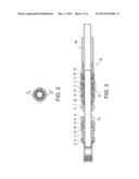
[0010] FIG. 2 is an end view of the anchor of FIG. 1;
[0011] FIG. 3 is a cross-sectional view of the anchor of FIG. 1 along line A-A of FIG. 2;
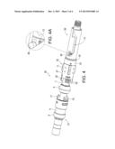
[0012] FIG. 4 is a perspective view of the anchor in transition between a release position and a set position;
[0013] FIG. 4A is a magnified view of a portion of the anchor of FIG. 4;
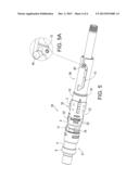
[0014] FIG. 5 is a perspective view of the anchor in the set position; and
[0015] FIG. 5A is a magnified view of a portion of the anchor of FIG. 5.
DETAILED DESCRIPTION OF VARIOUS EMBODIMENTS
[0016] The detailed description set forth below in connection with the appended drawings is intended as a description of various embodiments of the present invention and is not intended to represent the only embodiments contemplated by the inventor. The detailed description includes specific details for the purpose of providing a comprehensive understanding of the present invention. However, it will be apparent to those skilled in the art that the present invention may be practiced without these specific details.
[0017] Referring to FIGS. 1 to 5, an anchor is shown and a method is described for anchoring tubing during well pumping operations. In one embodiment, the anchor 30 includes a mandrel 8, for connection to a tubing string, a slip body assembly 21, a cone 4, a drag block assembly 32, and a sub assembly 36. In one embodiment, the mandrel is threaded at both ends, and the threading may form pin or box ends, for connection to the tubing string.
[0018] The sub assembly 36 is positioned near a lower end of the mandrel. In one embodiment, the sub assembly has a bore and the mandrel extends through the bore. In a further embodiment, the lower end of the mandrel extends beyond one end of the sub assembly. The sub assembly includes a mechanism for facilitating the setting and releasing of the anchor.
[0019] In one embodiment, the mechanism is a pin and slot design, wherein the slot provides a recess in which the pin may rest when the anchor is in each of a set position and a release position. The illustrated embodiment shows a sample mechanism comprising a pin 40 and a C-shaped slot 13. C-shape slot 13 has an upper recess and a lower recess joined by an axially extending connector slot. The upper recess and lower recess each extend away from the axially extending connector slot on the same side. The upper recess and lower recess each have a return nook and the two nooks face towards each other to provide the recesses with opposing hook-like shapes. Pin 40 is slidably movable in slot 13. In one embodiment, the pin is attached to the outer surface of the mandrel such that it does not move relative to the mandrel, and the position of pin 40 in slot 13 is adjustable by rotating the mandrel and/or moving the mandrel axially relative to the sub assembly. While slot 13 is generally C-shaped, the distance by which the recesses extend away from the axially extending connector slot and/or the shape of the recesses may vary in different embodiments of the anchor. In one embodiment, the recesses extend away from the axially extending connector slot by a specific distance and are shaped such that pin 40 can be moved from within one of the recesses to the axially extending connector slot by rotating the mandrel less than half a full turn relative to the sub assembly. In a further embodiment, the recesses extend away from the axially extending connector slot by a specific distance and are shaped such that pin 40 can be moved from within one of the recesses to the axially extending connector slot by rotating the mandrel about a quarter turn relative to the sub assembly. Therefore, the amount of rotation of the mandrel relative to the sub assembly that is required to move pin 40 from one of the recesses to the axially extending connector slot depends on the distance of the extension and the shape of the recesses.
[0020] The sub assembly may further include a retainer ring 19 that encircles the outer surface (i.e. the surface facing away from the mandrel) of the sub assembly near its other end. In one embodiment, the retainer ring provides a beveled edge which may facilitate the anchor's entry into a wellbore.
[0021] The other end of the sub assembly is connected to the drag block assembly, which comprises a drag block retainer 10, drag blocks 2, drag block springs 3, a drag body housing 27, lower slip springs 14, and lower slips 22. The drag block assembly may have a bore and the mandrel extends through the bore. In one embodiment, the sub assembly is connected to the drag block retainer, which may be held in place by the retainer ring. The drag block springs are placed below the drag blocks, to urge the drag blocks radially outwardly away from the mandrel, while the drag block retainer and the drag body housing hold the edges of the drag blocks preventing them from being displaced from the drag block assembly by the drag block springs. In one embodiment, the outer surface (i.e. the surface facing away from the mandrel) of the drag blocks and/or the lower slips may be textured for contacting and frictionally engaging the inner surface of a wellbore such that movement of the drag blocks and/or slips and therethrough the drag body housing is resisted relative to the wellbore. The textured surface may include for example laterally positioned ratchet type teeth or the like.
[0022] In one embodiment, an annulus is formed in the space between the inner surface of the drag block assembly and the outer surface of the mandrel. In another embodiment, a connector sleeve 7, having a first end and a second end, is provided in the annulus.
[0023] Attached to the first end of the sleeve is cone 4, and at the second end is a mandrel cap 11. The cone may be in the form of a ring, extending fully around the mandrel. In one embodiment, the cone is frustoconical in shape. The sleeve helps carry the drag block assembly with the mandrel, as the anchor is being placed in the well, but is not attached to the mandrel or the drag block assembly so the sleeve is free to move axially in the annulus to a certain extent. The sleeve's axial movement may be limited by the mandrel cap. In one embodiment, the mandrel cap prevents the sleeve from moving beyond a certain point towards the sub assembly.
[0024] The slip body assembly is positioned near an upper end of the mandrel. The slip body assembly comprises upper slips 16, upper slip springs 15, and a slip engagement mechanism. In one embodiment, the slip body assembly has a bore and a portion of the mandrel extends through the bore. In yet another embodiment, the upper end of the mandrel may extend beyond one end of the slip body assembly. The slip engagement mechanism comprises a spring cage 5 enclosing a spring 6, a spring retaining ring 18, and a spring cage cap 9. The spring 6 may be a coil spring with its coils wrapped around the outer surface of the mandrel. The spring cage cap holds the spring cage in place. The outer surface (i.e. the surface facing away from the mandrel) of the upper slips may be textured, for contacting and frictionally engaging the inner surface of a wellbore. In one embodiment, the textured surface includes laterally positioned ratchet type teeth or the like. In a further embodiment, the slip body assembly includes a releasing slip 17, which functions in a similar manner as the upper slips, except for the outer surface of the releasing slip may or may not be textured for contacting, but not frictionally engaging, the inner surface of a wellbore. For example, the releasing slip may have flattened teeth, rather than ratchet teeth.
[0025] The slip body assembly is positioned on one side of the cone, while the drag block assembly is positioned on the other side, such that the cone is positioned axially between the upper slips and the lower slips. The sub assembly, together with the drag block assembly, is moveable axially along the outer surface of the mandrel between a first position and a second position. The slip body assembly is moveable axially along the outer surface of the mandrel between a first position and a second position.
[0026] In FIGS. 1, 2, and 3, the anchor is shown in the release position. In the release position, the pin rests in the return nook of the upper recess of the slot. When the pin is in the return nook of the upper recess, the sub assembly and the drag block assembly are in the first position, wherein the lower slips are retracted about the outer surface of the mandrel. The lower slip springs bias the slips to their retracted position. In the release position, the slip body assembly is also in the first position, wherein the upper slips are retracted about the outer surface of the mandrel. The upper slip springs bias the slips to their retracted position. Further, the spring 6 may be in a neutral position when the anchor is in the release position.
[0027] When the anchor is in the set position, as shown in FIG. 5, the pin rests in the return nook of the lower recess of the slot. When the pin is in the return nook of the lower recess, the sub assembly and the drag block assembly are in the second position, wherein the lower slips are engaged, driven radially outwardly, i.e. the slips have ridden up on the cone, causing them to project outwards beyond the neutral outer diameter of the anchor in its release position. In the set position, the slip body assembly is in the second position, wherein the spring 6 is under compression, causing the upper slips to be engaged, i.e. to ride up on the cone, allowing the slips to project radially outwardly beyond the neutral outer diameter of the anchor in its release position.
[0028] The anchor may be used in different types of wells, including deviated and horizontal wells. The anchor may be used to limit axial movement of a tubing string. In one embodiment, the anchor may also be used to limit left-hand (or counterclockwise when looking down the well) rotation of the tubing string. When in use, the anchor is connected directly or indirectly at its upper end to an upper tubing string, and may also be connected directly or indirectly to a lower tubing string at its lower end. Each end of the anchor may be secured to the tubing string by, for example, a threaded connection, or the like. When the anchor is placed at a desired position in a well, with its upper end being closer to the well opening at the ground surface than its lower end, the anchor may be put into the set position from the release position in a number of ways. In the desired position, the drag block assembly should frictionally engage the inner wall of the wellbore such that the drag block assembly is substantially immovable within the wellbore unless the tension or weight on the upper tubing string exceeds a certain threshold. This threshold may be determined by a process of picking up and slacking off the tubing string, as known to a person of ordinary skill in the art. During the process of setting or releasing the anchor, the picking up and slacking off are sufficient to move the mandrel within the drag block assembly but are less than the threshold required to move the drag block assembly so that the drag block assembly remains substantially stationary relative to the wellbore and does not move with the mandrel.
[0029] In one embodiment, the anchor is put into the set position by moving the pin from the upper recess to the lower recess of the slot. This way the upper slips and the lower slips move toward each other and up on to the cone. In a further embodiment, the pin may be moved to the lower recess by:
[0030] 1. dislodging the pin from the return nook of the upper recess by picking up the upper tubing string. FIG. 4 shows the pin in the upper recess but disengaged from the return nook.
[0031] 2. rotating the upper tubing string about a quarter turn to the right (i.e. clockwise, when looking down the well), thereby placing a right-hand torque on the tubing string and the mandrel, while the drag block assembly is held steady.
[0032] The rotation moves the pin out of the upper recess and into the axially extending connector slot.
[0033] 3. slacking off the upper tubing string and the mandrel to move the pin through the axially extending connector slot towards the lower recess, while simultaneously releasing the right-hand torque. As the pin moves through the axially extending connector slot in the direction of the lower recess, the mandrel compresses spring 6, which then urges the upper slips towards the cone, thereby eventually pushing the cone towards the drag block assembly and sliding the cone under the lower slips to put the lower slips into the engaged position. The movement of the mandrel also urges the upper slips on to the cone and into the engaged position. In the engaged position, the outer surfaces of the upper and lower slips frictionally engage the inner wall of the wellbore. Releasing the torque allows the pin to follow the path of slot 13 and as the pin moves into the lower recess, the torque on the tubing string is completely dissipated due to the shape of the path; and
[0034] 4. picking up the upper tubing string and mandrel until the pin engages the return nook in the lower recess to lock the anchor in the set position. FIG. 5 shows the anchor in the set position wherein the pin is engaged with the return nook in the lower recess. In the set position, the spring is under compression, which may put the anchor in tension to help keep the pin in the return nook of the lower recess. In one embodiment, the upper tubing string may be picked up after the anchor is set, to pull the cone up slightly to ensure that the upper slips are fully engaged.
[0035] To test whether the anchor is set properly, the tubing string may be picked up and slacked off beyond the above-mentioned threshold. If there is no axial movement of the tubing string during testing, the anchor is likely set.
[0036] When it is set, the anchor limits axial movement of the tubing string. Since only less than half a full turn is required to set the anchor, the risk of backing off the threaded connections in the tubing string during the setting process may be reduced. After it is set, the anchor may operate with the string in compression, in tension, and in neutral.
[0037] The anchor may be installed at any point along the tubing string, including the tubing string section just below, or just above, the pump.
[0038] The anchor may be released in a number of ways. In one embodiment, the anchor is released from the set position by moving the pin from the lower recess to near the upper recess of the slot. In a further embodiment, the pin may be displaced from the lower recess by:
[0039] 1. disengaging the pin from the lower recess by slacking off and rotating the upper tubing string about a quarter turn to the right from above the anchor, thereby placing a right-hand torque on the tubing string and the mandrel, while the drag block assembly remain stationary; and
[0040] 2. picking up the upper tubing string, while maintaining the right-hand torque, to cause the lower slips to slide off of the cone into the disengaged position, and to release the compression in the spring allowing the upper slips to disengage from the cone.
[0041] The releasing slip may assist in disengaging the slip body assembly. Since the releasing slip does not frictionally engage the inner wellbore surface to the same extent as the upper slips, the releasing slip retracts to its disengaged position more readily than the upper slips. The retraction of the releasing slip makes room to allow the upper slips to free themselves from the inner surface and to retract to the disengaged position.
[0042] In a further embodiment, an emergency release mechanism is provided, wherein the pin is part of a ring that fits in the annulus between the sub assembly and the mandrel. The ring includes screws 12. In the event that the anchor cannot be released by the above-described procedure, the upper tubing string may be picked up until the screws are sheared, which causes the ring to fall away from the anchor and thereby releasing the upper and lower slips.
[0043] The previous description of the disclosed embodiments is provided to enable any person skilled in the art to make or use the present invention. Various modifications to those embodiments will be readily apparent to those skilled in the art, and the generic principles defined herein may be applied to other embodiments without departing from the spirit or scope of the invention. Thus, the present invention is not intended to be limited to the embodiments shown herein, but is to be accorded the full scope consistent with the claims, wherein reference to an element in the singular, such as by use of the article "a" or "an" is not intended to mean "one and only one" unless specifically so stated, but rather "one or more". All structural and functional equivalents to the elements of the various embodiments described throughout the disclosure that are known or later come to be known to those of ordinary skill in the art are intended to be encompassed by the elements of the claims. Moreover, nothing disclosed herein is intended to be dedicated to the public regardless of whether such disclosure is explicitly recited in the claims. For US patent properties, it is noted that no claim element is to be construed under the provisions of 35 USC 112, sixth paragraph, unless the element is expressly recited using the phrase "means for" or "step for".
User Contributions:
Comment about this patent or add new information about this topic:
Images included with this patent application:
 |  |
 |  |
 |
| New patent applications in this class: | |
| Date | Title |
|---|---|
| 2018-01-25 | Capture method for flow back retrieval of borehole plug with a lower slip assembly |
| 2018-01-25 | Gripping arrangement |
| 2017-08-17 | Downhole anchor |
| 2016-12-29 | Automated pipe tripping apparatus and methods |
| 2016-09-01 | Running tool and liner hanger contingency release mechanism |
| Top Inventors for class "Wells" | |
| Rank | Inventor's name |
|---|---|
| 1 | Michael L. Fripp |
| 2 | Jean Marc Lopez |
| 3 | Michael H. Johnson |
| 4 | Jørgen Hallundbaek |
| 5 | Dennis P. Nguyen |