Patent application title: COOLING DEVICE FOR A JET ENGINE
Inventors:
Sacha Pichel (Berlin, DE)
Assignees:
Rolls-Royce Deutschland Ltd & Co KG
IPC8 Class: AF01D2512FI
USPC Class:
415116
Class name: Rotary kinetic fluid motors or pumps with diversely oriented inlet or additional inlet for diverse fluid (e.g., heating, cooling or mixed working fluid, etc.)
Publication date: 2013-11-14
Patent application number: 20130302143
Abstract:
The present invention relates to a cooling device for a jet engine having
an axial compressor with several compressor stages including a rotor with
rotor blades, a stator with stator vanes and an annulus. In order to
reduce the temperature of the components at the outlet of the
high-pressure compressor by simple measures and hence to increase the
efficiency of a jet engine, a slot-like branch opening surrounding the
rotor for a cooling airflow diverted from the main airflow into a first
cavity upstream of the rotor is provided upstream of the last compressor
stage of the axial compressor, with passage openings being arranged in
the rotor for passing on the diverted cooling airflow from the first
cavity into a second cavity downstream of the rotor.Claims:
1. Cooling device for a jet engine having an axial compressor with
several compressor stages including a rotor with rotor blades, a stator
with stator vanes and an annulus, characterized in that upstream of the
last compressor stage of the axial compressor, a slot-like branch opening
surrounding the rotor is provided for a cooling airflow diverted from the
main airflow into a first cavity upstream of the rotor and that passage
openings are arranged in the rotor for passing on the diverted cooling
airflow from the first cavity into a second cavity downstream of the
rotor.
2. Cooling device in accordance with claim 1, characterized in that the passage openings pass circumferentially/axially through the rotor and are arranged concentrically to the rotor axis.
3. Cooling device in accordance with claim 1, characterized in that a heat shield with sealing lips and heat shield openings is provided in the first cavity between the rotor and the stator and that the cooling airflow is passed through the heat shield openings and through passage openings on the axial blade mountings of the rotor blades into the second cavity.
4. Cooling device in accordance with claim 1, characterized in that the slot-like branch opening is provided as a step projecting into the annulus.
5. Cooling device in accordance with claim 1, characterized in that an annulus limitation between rotor and stator is designed as a gap seal.
Description:
[0001] This invention relates to a cooling device for a jet engine having
an axial compressor with several compressor stages including a rotor with
rotor blades, a stator with stator vanes and an annulus.
[0002] In jet engines, the air mass flow is compressed before entering the combustion chamber. Modern jet engines with axial compressors have several compressor stages. A compressor stage of an axial compressor includes a rotor stage, in which pressure and temperature as well as the speed increase, and a stator stage, in which the pressure increases at the expense of the speed. The stator stages are firmly connected to the inside of the compressor casing.
[0003] The high compression of the air in the successive compressor stages causes a steep temperature increase. Experience has shown that in a jet engine with high pressure compressor (HPC), the temperature difference between the individual stages is about 50° C., as a result of which the compressed air exits the last compressor stage at temperatures of up to 600° C. The air so compressed and heated then flows into the combustion chamber, inside which fuel is supplied.
[0004] The temperatures of up to 600° C. downstream of the last compressor stage are detrimental to the strength of the materials. The rotor is, in particular due to heat conduction from the rotor blades, subject to a higher relative temperature than the stator and the further static components. Furthermore, the rotor is subject to a high mechanical load due to the rotation, besides higher relative temperatures.
[0005] It is already known from DE 103 31 834 A1 that the heat content of the highly compressed combustion air of a motor or of an engine can be reduced by the use of coolers and hence the efficiency can be increased.
[0006] DE 602 21 558 T2 describes an engine with turbine blade in which air is diverted from an intermediate-pressure section of the axial compressor and passed to the turbine blade in order to cool the latter.
[0007] An increase of the thermodynamic efficiency is possible with these solutions. The known solutions for cooling of the compressor air and of the engine components however have the disadvantage that the complexity and the weight of the turbine increase.
[0008] The object underlying the present invention is to reduce the temperature of the components at the outlet of the high-pressure compressor of a jet engine by simple measures and hence to increase the efficiency, i.e. the cost effectiveness and the performance, of a jet engine.
[0009] Solution to the above problematics is provided in accordance with the invention by arranging upstream of the last compressor stage of the axial compressor a slot-like branch opening surrounding the rotor for a cooling airflow diverted from the main airflow into a first cavity upstream of the rotor of the last compressor stage, where the cavity can also be an integral part of the rotor, and passage openings in the rotor for passing on the diverted cooling airflow from the first cavity into a second cavity downstream of the rotor. Hence the outlet area of the axial compressor is supplied with cooler air of a preceding stage.
[0010] Due to the difference in the rotor diameters of the last compressor stage and of the compressor stage arranged upstream of it, the branch opening is designed as a stage. This stage projects into the annulus and passes a part of the main airflow as a cooling airflow out of the annulus.
[0011] The passage openings are arranged concentrically to the rotor axis and may pass obliquely/ axially through the rotor. The annulus limitation between rotor and stator is designed as a gap seal to prevent return flows.
[0012] In an embodiment of the cooling device, a heat shield with sealing lips and heat shield openings is provided in the first cavity between the rotor and the stator. The cooling airflow is passed through the heat shield openings and through the passage openings on the axial blade mountings of the rotor blades into the second cavity.
[0013] The advantages of the solution in accordance with the invention are that with simple design measures, the material temperatures of the components at the end of the high-pressure compressor can be reduced and hence the use of less expensive materials is possible. When the previous materials are retained, an increase in the temperatures at the compressor outlet and hence in the efficiency is possible. A further advantage is that in comparison with already known solutions for air cooling a lower pressure loss is recorded. There is also a weight advantage when compared with already known solutions.
[0014] The device in accordance with the invention for cooling a jet engine in the area of the last compressor stage is explained in greater detail in light of the accompanying figures.
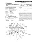
[0015] FIG. 1 shows a section of an engine in the area of the last compressor stage in partial sectional view,
[0016] FIG. 2 shows an enlarged section of the engine shown in FIG. 1 in the area of the last compressor stage in partial sectional view,
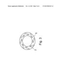
[0017] FIG. 3 shows a schematic sketch of an embodiment of the passage openings arranged in annular form, and
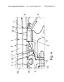
[0018] FIG. 4 shows a section of a further embodiment of an engine in the area of he last compressor stage in partial sectional view.
[0019] FIG. 1 shows a section of an axial compressor of a jet engine in partial sectional view, including a rotor 5 with rotor blades 7, a stator 6 with stator vanes 8 and an annulus 10. The rotational axis of the jet engine is below the section and is not shown. The preceding compressor stages increase the pressure of the main airflow 11 in the annulus 10. Upstream of the last compressor stage 9 of the axial compressor, a slot-like branch opening 1 surrounding the rotor 5 is provided at the annulus 10, projects in stage-like form into the annulus 10 and passes a part of the main airflow 11 as a cooling airflow 12 into a first cavity 3 upstream of the rotor 5 of the last compressor stage 9. The cavity 3 can also be an integral part of the rotor 5. The diverted air mass flow of the cooling air 12 ensures, due to the kinetic energy of the air, the formation of a dynamic pressure in the first cavity 3 located underneath the stage 16. The compressed cooling air 12 is passed through passage openings 2 arranged concentrically to the rotor axis in rotor 5 into the second cavity 4 downstream of the last compressor stage 9 and there cools the rotor 5 and the stator 6. At the same time, the radial blade mountings 14 provided in the rotor 5 are cooled. A gap seal 13 prevents the around 50° C. hotter air of the main airflow 11 downstream of the last compressor stage 9 from reaching the second cavity 4.
[0020] FIG. 2 shows an enlarged section of FIG. 1. Due to the difference in the rotor diameters of the last compressor stage 9 and of the compressor stage arranged upstream of it, the branch opening 1 in the annulus 10 is designed as a stage 16, The cooling air 12 flowing into the first cavity 3 passes through the axially arranged, i.e. in axis direction, passage openings 2 in the rotor 5 into the second cavity 4. The rotor blades 7 are fixed to the rotor 5 by means of the radial blade mountings 14. The stator vanes 8 are firmly connected to the stator 6. The gap seal 13 is provided between the rotor 5 and the stator 6 and prevents an inflow of hot air from the main airflow 11 into the second cavity 4 downstream of the last compressor stage 9. Due to the decentralized inflow of the cooling air 12 into the second cavity 4, the air in the second cavity 4 can circulate.
[0021] FIG. 3 shows in schematic form and in an axial view an embodiment of the passage openings 2 arranged in annular form inside the rotor 5. They are arranged concentrically to the rotor axis and pass obliquely/ axially through the rotor 5, so that the air flows in a directed manner into the second cavity 4 and hence is imparted with a pre-swirl which further improves the circulation of the cooling airflow 12. In addition, the air cools the components and the rotor 5 through which air flows.
[0022] FIG. 4 shows an alternative embodiment of the device in accordance with the invention for cooling of a jet engine in the area of the last compressor stage 9. The slot-like branch opening 1 in the annulus 10 can here also be designed as a stage 16. A heat shield 17 with sealing lips 18 and heat shield openings 19 is arranged in the first cavity 3. Cooling air 12 from the first cavity 3 flows through the heat shield openings 19 in the heat shield 17 to the root of the rotor blades 7 with axial blade mountings 15 and through the passage openings 2' into the second cavity 4. The passage openings 2' are formed in this embodiment by gap openings in the area of the axial blade mountings 15.
[0023] Due to the decentralized inflow of the cooling air 12 into the second cavity 4, the air in the second cavity 4 can circulate. The gap seal 13 is designed such that an inflow of hot compressed air out of the main airflow 11 from the annulus 10 into the cavity 4 is prevented. In addition, the gap seal 13 prevents a return flow of the cooling air 12 into the annulus 10.
[0024] The embodiment shown in FIG. 4 has the advantage that the invention can be used with conventional axial blade root mountings 15.
[0025] It is furthermore advantageous that the components adjoining the second cavity 4, for example the rotor 5 and the stator 6, are flushed with cooling air 12. The cooling airflow 12 can furthermore be used for cooling further engine components.
LIST OF REFERENCE NUMERALS
[0026] 1 Branch opening
[0027] 2, 2' Passage openings
[0028] 3 First cavity
[0029] 4 Second cavity
[0030] 5 Rotor
[0031] 6 Stator
[0032] 7 Rotor blades
[0033] 8 Stator vanes
[0034] 9 Last compressor stage
[0035] 10 Annulus
[0036] 11 Main airflow
[0037] 12 Cooling airflow
[0038] 13 Gap seal
[0039] 14 Radial blade mountings
[0040] 15 Axial blade mountings
[0041] 16 Stage
[0042] 17 Heat shield
[0043] 18 Sealing lip
[0044] 19 Heat shield openings
User Contributions:
Comment about this patent or add new information about this topic:
Images included with this patent application:
 |  |
 |  |
 |
| Similar patent applications: | |
| Date | Title |
|---|---|
| 2013-10-03 | Mounting device for fan |
| 2013-10-03 | Mounting device for fan |
| 2013-10-17 | Mounting device for fan |
| 2013-10-17 | Mounting device for fan |
| 2013-11-28 | Fixing device for fan |
| New patent applications in this class: | |
| Date | Title |
|---|---|
| 2022-05-05 | Fluid pump and outlet check valve assembly thereof |
| 2018-01-25 | Efficient, low pressure ratio propulsor for gas turbine engines |
| 2018-01-25 | Ring segment system for gas turbine engines |
| 2017-08-17 | Gas turbine having an annular passage subdivided into annulus sectors |
| 2017-08-17 | Gas turbine |
| New patent applications from these inventors: | |
| Date | Title |
|---|---|
| 2012-11-15 | Gas-turbine engine with bleed-air tapping device |
| 2012-11-08 | Gas-turbine balancing device |
| 2009-01-15 | Apparatus and method for retaining bladed rotor disks of a jet engine |
| Top Inventors for class "Rotary kinetic fluid motors or pumps" | |
| Rank | Inventor's name |
|---|---|
| 1 | Gabriel L. Suciu |
| 2 | Frederick M. Schwarz |
| 3 | United Technologies Corporation |
| 4 | Brian D. Merry |
| 5 | Craig M. Beers |