Patent application title: Packaging Device
Inventors:
Shih-Hsiang Chen (Shenzhen, CN)
Shih-Hsiang Chen (Shenzhen, CN)
Jiahe Cheng (Shenzhen, CN)
Jiahe Cheng (Shenzhen, CN)
Assignees:
SHENZHEN CHINA STAR OPTOELECTRONICS TECHNOLOGY CO., LTD.
IPC8 Class: AB65D8530FI
USPC Class:
206454
Class name: Special receptacle or package for plate or sheet fragile or sensitive (e.g., glass mirror)
Publication date: 2013-11-14
Patent application number: 20130299376
Abstract:
The present invention provides a technical solution in which a packaging
device is introduced and it includes a container with at least one
positioning device arranged in inner surface of the container. And
further includes at least a buffering pad defined with holes in which
matches to the positioning device such that when the packaging device is
erected, the buffering pad is hanged over the container. Since the
buffering pads can be selected from soft material of cost effective, the
cost is therefore reduced.Claims:
1. A packaging device, wherein the packaging device includes: a cover
lid, a holder, a positioning device, and a buffering pad; the positioning
device being securely disposed on an inner surface of the holder, and the
positioning device being arranged to side of the inner surface of the
cover lid; the buffering pad being defined with a retaining hole to
receive the positioning device, the inner surface of the cover lid being
defined with recesses in which the positioning device engages, wherein
when the packaging device is erected, the buffering pad is hanged upon
the positioning device and positioned between the cover lid and the
holder.
2. The packaging device as recited in claim 1, wherein the positioning device is a stud projected from an inner surface of the holder.
3. The packaging device as recited in claim 1, wherein the positioning device has a threaded end, and an inner surface of the cover lid is defined with threaded recesses in which the threaded end is securely positioned within the threaded recesses.
4. The packaging device as recited in claim 1, wherein the number of the positioning device can be multiple located on one side of the bottom, or alternatively, located either sides of the bottom, or alternatively, located on four sides of the bottom.
5. The packaging device as recited in claim 1, wherein the buffering pad is soft and flexible material.
6. The packaging device as recited in claim 5, wherein the soft and flexible material is a composite foam made from expandable polyethylene.
7. The packaging device as recited in claim 1, wherein the packaging device is used to pack the liquid crystal display panels.
8. A packaging device, wherein the packaging device includes: a container, a positioning device, and a buffering pad; wherein the positioning device is disposed on an inner surface of the container; wherein the buffering pad is defined with a positioning hole; and wherein the positioning device is retained within the retaining hole in a way when the packaging device is erected, the buffering pad is hanged over the positioning device.
9. The packaging device as recited in claim 8, wherein the container is configured with a holder and a cover lid; wherein the positioning device is disposed on a surface of the holder facing the cover lid, and wherein the cover lid is attached onto the holder.
10. The packaging device as recited in claim 8, wherein the undersurface of the cover lid is provided with recess corresponding to the positioning device which can be properly and securely seated within the recess so as to have the buffering pad properly arranged between the cover lid and the holder.
11. The packaging device as recited in claim 8, wherein the length of the positioning device equals to a distance between a surface of the holder and a surface of the cover lid.
12. The packaging device as recited in claim 8, wherein the positioning device is a stud projected from a bottom wall of the holder.
13. The packaging device as recited in claim 8, wherein an end of the positioning device is provided with thread, and a surface of the holder is defined with threaded recess in which the threaded end of the positioning device is retained within the threaded recess.
14. The packaging device as recited in claim 8, wherein the number of the positioning device can be multiple located on one side of the bottom, or alternatively, located either sides of the bottom, or alternatively, located on four sides of the bottom.
15. The packaging device as recited in claim 8, wherein the buffering pad is soft and flexible material.
16. The packaging device as recited in claim 5, wherein the soft and flexible material is a composite foam made from expandable polyethylene.
17. The packaging device as recited in claim 8, wherein the packaging device is used to pack the liquid crystal display panels.
Description:
FIELD OF THE INVENTION
[0001] The present invention relates to a field of packaging, and more particularly to a packaging device.
BACKGROUND OF THE INVENTION
[0002] According to the existing manufacturing process of a liquid crystal display, it generally includes the following steps:
[0003] Preliminary manufacturing process of array: making array substrate and the color filter substrate;
[0004] Intermediate manufacturing process of cell: marrying the array substrate and the color filter substrate, and gluing the two after filling liquid crystal between the array substrate and the color filter substrate, then dissecting the substrate into proper dimension for liquid crystal display panel;
[0005] Final manufacturing process of assembling module: the panel will then be assembled with other parts, such as a backlight module, printed circuit hoard, and frame etc so as to completely the assembly of a liquid crystal display.
[0006] During the above described manufacturing processes, after the those two substrates were married and filled with liquid crystal, and dissected, those individual panels have to be well packed so as to deliver to the next workstation for modulating thereby completing the manufacturing processes.
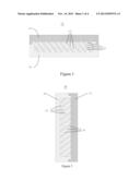
[0007] As shown in FIGS. 1 and 2, an existing packaging device 10 generally includes a cover lid 11, and a holder 12 within which a liquid crystal display panel 14 is disposed along with some buffering material. The liquid crystal display panel is disposed within the holder 12 one after another with the buffering material/layer imposed alternatively therebetween. Once a certain or preset number of the panels are stacked, the lid is placed on, and the packaging device 10 is erected or displaced on a vehicle taking to next workstations.
[0008] Since the buffering material 13 is comparatively soft, and once the packaging device 10 is erected, the buffering material 13 is also erected. However, as the buffering material 13 is soft, those buffering material 13 tends to be slacked down resulted from the gravity. As a result, only a few buffering material 13 is in contact with the panels 14 or disposed between every two adjacent panels 14. Once the upper portions of the panels 14 lose protection from the buffering material 14, the panels 14 tend to be damaged once they come into contact with each other. In order to resolve this issue, the exiting buffering material 13 has to be incorporated with certain stiffness such that when the buffering material 14 is erected, it will not slack down. The existing buffering material 13 is made from thin layer of polypropylene (PP). With the certain stiffness provided by the PP, the buffering material 13 may properly in contact with the cover lid 11 and holder 12 so as to evenly support and position the panels 14. In addition, once the packaging device 10 is erected, the buffering material 13 will not slack down. It is believed that it can reach to its intended purposes.
[0009] Nevertheless, for those buffering material with certain stiffness, it costs more and lots.
SUMMARY OF THE INVENTION
[0010] It is therefore the objective of the present invention to provide a packaging device in which a soft and cost-effective buffering pad can be used. The buffering pad can effectively and securely , separate two adjacent panels when the packaging device is erected. The panels can be readily protected, while the cost can be reduced.
[0011] In order to resolve the above described issue, the present invention provides a technical solution by introducing a packaging device which includes a cover lid and a holder defining a receiving space having a plurality of recesses defined in the inner surface thereof. A positioning device is further provided and further comprises at least a buffering pad defined with a retaining hole in which the positioning device attached thereof. The buffering pad can be properly supported by inner surface of the holder when the positioning device is securely seated within the recess such that the at least one buffering pad is securely hanged between the cover lid and the holder.
[0012] Wherein the positioning device is a stud projected from a bottom wall of the holder.
[0013] Wherein the stud has a threaded bottom securely rooted within a threaded hole located in a bottom wall the holder.
[0014] Wherein the number of the positioning device can be multiple located on one side of the bottom, or alternatively, located either sides of the bottom, or alternatively, located on four sides of the bottom.
[0015] Wherein the buffering pad is soft and flexible material.
[0016] Wherein the buffering pad is made from expandable polyethylene.
[0017] Wherein the packaging device is used to pack the liquid crystal display panels.
[0018] In order to resolve the above described technical problem, the present invention provides a technical solution in which a packaging device is introduced and it includes a container with at least one positioning device arranged in inner surface of the container. And further includes at least a buffering pad defined with holes in which matches to the positioning device such that when the packaging device is erected, the buffering pad is hanged over the container.
[0019] Wherein the container is configured with a holder and a cover lid enclosing the holder, wherein the positioning device is arranged on an undersurface of the cover lid.
[0020] Wherein the undersurface of the cover lid is provided with recess corresponding to the positioning device which can be properly and securely seated within the recess so as to have the buffering pad properly arranged between the cover lid and the holder.
[0021] Wherein the length of the positioning device equals to a distance between the cover lid to a top surface of the holder.
[0022] Wherein the positioning device is a stud projected from a bottom wall of the holder.
[0023] Wherein the stud has a threaded bottom securely rooted within a threaded hole located in a bottom wall of the holder.
[0024] Wherein the number of the positioning device can be multiple located on one side of the bottom, or alternatively, located either sides of the bottom, or alternatively, located on four sides of the bottom.
[0025] Wherein the buffering pad is soft and flexible material.
[0026] Wherein the buffering pad is made from expandable polyethylene.
[0027] Wherein the packaging device is used to pack the liquid crystal display panels.
[0028] The present invention can be concluded with the following advantages as compared with the prior arts. The present invention provides a packaging which includes a container with at least one positioning device arranged in inner surface of the container. And further includes at least a buffering pad defined with holes in which matches to the positioning device such that when the packaging device is erected, the buffering pad is hanged over the container. As a result, the buffering pad can be properly arranged between every two adjacent panels such that the panels are well protected and separated from each other from damaging during transportation. In addition, because of the introduction of the positioning device, the buffering pad can be selected from soft and cost effective material thereby reducing the overall cost.
BRIEF DESCRIPTION OF DRAWINGS
[0029] FIG. 1 is an illustrational and sectional view of a prior art packaging device in which LCD panels arc packed horizontally;
[0030] FIG. 2 is also an illustrational and sectional view of the prior art packaging device but with the packaging device is erected and the panels are arranged vertically;
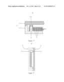
[0031] FIG. 3 is a partial, sectional view of a packaging device made in accordance with the present invention in which panels are arranged horizontally therein;
[0032] FIG. 4 is an illustrational and sectional view of the packaging device which is held vertically along with the panels packed inside;
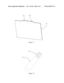
[0033] FIG. 5 is perspective view of a buffering pad made in accordance with the present invention;
[0034] FIG. 6 is a perspective view of a positioning device made in accordance with the present invention;
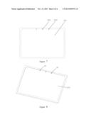
[0035] FIG. 7 is a perspective view of a holder showing threaded holes are defined on a bottom thereof; and
[0036] FIG. 8 is a perspective view of the holder showing the positioning device is projected from the bottom thereof.
DETAILED DESCRIPTION OF PREFERRED EMBODIMENT
[0037] Detailed description will be given along with accompanied drawings.
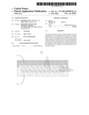
[0038] Referring to FIGS. 3, 4, and 5, FIG. 3 is a partial, sectional view of a packaging device made in accordance with the present invention in which panels are arranged horizontally therein; FIG. 4 is an illustrational and sectional view of the packaging device which is held vertically along with the panels packed inside; and FIG. 5 is perspective view of a buffering pad made in accordance with the present invention.
[0039] The packaging device 20 made in accordance with the present invention generally includes a container 21, a positioning device 22, and a buffering pad 23. The container 21 is configured with a cover lid 211 and a holder 212 on which the cover lid 211 is seated.
[0040] The positioning device 22 is securely attached to a bottom of the holder 212 and extends upward therefrom. The buffering pad 23 includes a tab portion 231 along a side thereof, and the tab portion 231 is defined with a plurality of retaining holes 232. The buffering pad 23 can be made and selected from cost effective soft material, such as composite foam, for example, expandable polyethylene covered with a polyethylene film on its surface.
[0041] When the packaging device 20 is used to pack the panels, a first buffering pad 212 is disposed on the bottom of the holder 212 with the retaining holes 232 engage with the positioning device 22. After the first buffering pad 212 is deployed, a first panel 24 is placed thereupon. Then a second buffering pad 23 is disposed onto the first panel 24, and again with the retaining holes 232 engage with the positioning device 22. By this arrangement, a preset or predetermined number of panels 24 can be properly and securely disposed within the holder 212 with every two adjacent panels 24 is interposed with a buffering pad 23. Once the preset or predetermined number of panels 24 is disposed within the holder 212, the cover lid 211 is covered onto the holder 212. Then the packaging device 20 can be erected and then put onto a carrier or vehicle and transported to next workstation. Once the packaging device 20 is erected or held vertically, the positioning device 22 is located on top portion. Since the buffering pads 23 are engaged with the positioning device 22. all the buffering pads 23 are held vertically therefore providing excellent buffering protection.
[0042] Alternatively, the tab portion 231 can be omitted and the retaining holes 232 can be defined along the side of the buffering pad 231.
[0043] Alternatively, the positioning device 22 can be fixedly attached to a ceiling of the cover lid 211 and extends downward. In assembling, a first buffering pad 23 can be laid down the bottom of the holder 23 firstly, and then a panel 24 is placed onto the first buffering pad 23. Then, a second buffering pad 23 is deployed over the first panel 24, and then a second panel 24 is disposed thereon. With a layer of buffering pad 23, and a layer of panel 24, a preset or predetermined number of panels 24 can be disposed within the holder 212. Then aligning all of the retaining holes 232 of each buffering pad 23, and eventually, the cover lid 211 is put onto the holder 212 with the positioning device 22 passes through all of the retaining holes 232. Once the packaging device 20 is erected vertically, the entire buffering pad 23 will be properly supported and hanged vertically within the packaging device 20 while providing excellent buffering effect to the panels.
[0044] Furthermore, a ceiling of the cover lid 211 is provided with recess 2111 with respect to the positioning device 22. In assembling, the positioning device 22 can be readily rooted into the recess 2111, and then the buffering pads 23 can be properly disposed between the cover lid 211 and the holder 212. Alternatively, the recess 2111 defined in the inner surface of the cover lid 211 can be omitted, while the length of the positioning device 22 is specially tailored such that it equals to the distance between the ceiling of the cover lid 211 and the bottom of the holder 212. Once the cover lid 211 is attached to the holder 212, the positioning device 22 can be held firmly between the cover lid 211 and the holder 212 so as to properly hold the buffering pad 23 therebetween.
[0045] Referring now to FIGS. 6, 7 and 8. FIG. 6 is a perspective view of a positioning device made in accordance with the present invention. FIG. 7 is a perspective view of a holder showing threaded holes are defined on a bottom thereof; and FIG. 8 is a perspective view of the holder showing the positioning device is projected from the bottom thereof.
[0046] The positioning device 22 can be embodied to include with a threaded portion 221, while the recess 2121 in the bottom of the holder 212 can be a threaded hole. Accordingly, the positioning device 22 can be bolted within the threaded recess 2121. The holder 212 can be provided with a plurality of threaded recesses 2121, and they can be arranged on a side of the bottom. Alternatively, opposite sides of the bottom can be arranged with the threaded recesses 2121, or alternatively, totally four sides of the bottom can be defined with threaded recesses 2121. In other alternatively, the positioning device 22 can be arranged in the bottom of the holder 212 based on different buffering pads 23 of different dimensions. As a result, different buffering pads 23 can all be used in a common holder 212. Alternatively, the threaded recess 2121 can also be arranged on the ceiling of the cover lid 211. Since it works and functions in the same way, no further description is given.
[0047] Alternatively, the positioning device 22 can use other arrangement other than threaded engagement between the threaded portion 221 and threaded recess 2121. For example, a projection can he directly formed on the bottom of the holder 212 and then extends therefrom. Alternatively, the projection can also be rooted from the ceiling and extends downward therefrom. The projection can be any geometry, such as circular, rectangular, and other suitable shape.
[0048] In the present invention, the positioning device 22 is disposed on the inner surface the container 21, and the buffering pads 23 and the panels 24 are alternatively disposed in the space defined by the container 21. In addition, the retaining holes 232 of the buffering pads 23 are engaged with the positioning device 22. The buffering pads 23 can be selected from soft material of cost effective. After the cover lid 211 is engaged with the holder 212, the packaging device 20 can be readily carried by an automatic vehicle and other suitable means. Once the packaging device 20 is erected vertically, the buffering pads 23 are also held vertically with the help of the positioning device 22. The buffering pads 23 will not slack down because of its softness. As a result, no matter how the packaging device 20 is arranged, every two adjacent panels 24 are well separated and protected by the buffering pad 23 sandwiched therebetween. Since the buffering pads 23 can be selected from soft material of cost effective, the cost is therefore reduced.
[0049] Embodiments of the present invention have been described, but not intending to impose any unduly constraint to the appended claims. Any modification of equivalent structure or equivalent process made according to the disclosure and drawings of the present invention, or any application thereof, directly or indirectly, to other related fields of technique, is considered encompassed in the scope of protection defined by the clams of the present invention.
User Contributions:
Comment about this patent or add new information about this topic:
Images included with this patent application:
 |  |
 |  |
 |
| Similar patent applications: | |
| Date | Title |
|---|---|
| 2010-02-11 | Packaging device |
| 2012-02-16 | Packaging device |
| 2012-05-17 | Packaging device |
| 2013-10-24 | Packaging device |
| 2012-07-26 | Method and apparatus for packaging produce |
| New patent applications in this class: | |
| Date | Title |
|---|---|
| 2016-04-21 | Liquid crystal module packaging bag |
| 2016-04-21 | A box for carrying the liquid crystal display panel |
| 2016-03-24 | An apparatus for packaging the front frames of lcd modules |
| 2016-02-18 | Packaging apparatus |
| 2015-11-05 | Structure for fastening together resin members in substrate storing container |
| New patent applications from these inventors: | |
| Date | Title |
|---|---|
| 2017-05-18 | Backlight module and liquid crystal display device |
| 2016-05-19 | Transparent display panel and color filter substrate thereof |
| 2015-12-31 | Backlight assembly and liquid crystal display using the same |
| 2015-11-12 | Backlight module |
| 2015-10-22 | Packing box |
| Top Inventors for class "Special receptacle or package" | |
| Rank | Inventor's name |
|---|---|
| 1 | Donald E. Weder |
| 2 | Brett R. Glass |
| 3 | Daniel Lee Bizzell |
| 4 | Andrea Biondi |
| 5 | Nicole E. Glass |