Patent application title: COOLING LININGS
Inventors:
Milinda Holdsworth-Layton (Frederick, MD, US)
IPC8 Class: AA41D13005FI
USPC Class:
622593
Class name: Refrigeration structural installation with body applicator
Publication date: 2013-11-14
Patent application number: 20130298589
Abstract:
A cooling lining comprises an outer (116) and inner layer (118) for
example of woven material. On the inner layer are a number of pockets
(120) with air channels forming a lattice there between. Within each
pocket is a support member (130) with an insulation member (128) nearer
the front face of the pocket to hold the sides of the pocket taut or
substantially taut. Hydrophilic material (134) is inserted into the
pockets. The lining may form a cooling vest (100) or may comprise
separate members that can be attached to inside of a flak jacket by
Velcro strips.Claims:
1. A cooling lining comprising a outer member, pockets mounted on the
inner side of the outer member wherein spaces are provided between
pockets and the pockets are arranged to cool the air in the said spaces.
2. A cooling lining as claimed in claim 1 wherein some of the spaces are arranged to form continuous channels which can guide hot air away from the liner.
3. A cooling lining as claimed in claim 2 wherein outwardly directed spaces and transfer spaces are provided between the pockets arranged to conduct air to the continuous channels.
4. A cooling lining as claimed in claim 1 wherein the inner surface of each pocket comprises insulation material.
5. A cooling lining as claimed in claim 1 wherein an insulating material is placed against the inner surface of each pocket.
6. A cooling lining as claimed in claim 4 wherein the outer member also has insulating properties.
7. A cooling lining as claimed in claim 1 wherein the outer member is fireproof.
8. A cooling lining as claimed in claim 1 wherein the side surfaces of the pocket are permeable to water.
9. A cooling lining as claimed in claim 8 further comprising hydrophillic material within the pockets.
10. A cooling lining as claimed in claim 1 wherein the inner surface comprises moulded material and the pockets are moulded from the said moulded material.
11. A cooling lining as claimed in claim 10 wherein the moulded material comprises polyethylene.
12. A cooling lining as claimed in claim 1 wherein the outer member comprises woven material.
13. A cooling lining as claimed in claim 12 wherein each of the pockets is stitched on to the inner side of the outer member.
14. A cooling lining as claimed in claim 12 wherein the woven material is cotton.
15. A cooling lining as claimed in claim 1 wherein the walls of the pockets are kept taut or predominantly taut by support means within the pocket.
16. A cooling lining as claimed in claim 15 wherein the support means comprises a central part which is of smaller size than the pocket and is located within the pocket.
17. A cooling lining as claimed in claim 15 wherein a surrounding space surrounds the central part within the pocket surrounding the central part.
18. A cooling lining as claimed in claim 17 wherein hydrophillic substance is packed in to the surrounding space.
19. A cooling lining as claimed in claim 1 in the form of an article of clothing.
20. A cooling lining as claimed in claim 19 wherein the article of clothing comprises a cooling vest.
21. A cooling vest as claimed in claim 20 wherein the outer member has symmetrical or predominantly symmetrical front and back portions and lateral portions connecting the front and back portions to hold the front and back portions firmly on to the torso of the wearer's body.
22. A cooling vest as claimed in claim 21 wherein the front and back portions may have connecting means capable of releasably holding the linings on the wearers body.
23. A cooling vest as claimed in claim 22 wherein the connecting means comprise mechanical fastening means.
24. A cooling vest as claimed in claim 23 wherein the mechanical fastening means are selected from the group comprising zips, buttons and press studs.
25. A cooling vest as claimed in claim 21 wherein at least one space defining a convection channel runs the majority of the vertical length of the front and rear portion of the cooling vest.
26. (canceled)
27. (canceled)
Description:
[0001] This invention relates to cooling linings.
[0002] The term "linings" as used herein is intended to cover any article of material adapted to surround a part of a body (either a human body or a body housing liquid) and specifically includes vests, flak jacket linings waistcoats and sheaths in to which canteens are placed and stored.
[0003] Cooling linings are known comprising pockets in to which cooling material is introduced, the pockets being arranged in such a manner that the cooling material cools the body.
[0004] We have found that there are problems arising out of this arrangement.
[0005] According to one aspect of the present invention there is provided a cooling lining comprising an outer member, pockets mounted on the inner side of the outer member wherein spaces are provided between pockets and the pockets are arranged to cool the air in the said spaces. Preferably a hydrophillic material is inserted into the pockets. Some spaces are preferably arranged to form continuous channels which can guide air away from the lining. Where the lining forms part of an article of clothing these channels may be upward vertical or substantially vertical channels leading to the upper part of the linings. There are preferably also outwardly directed spaces and transfer spaces between the pockets arranged to conduct air to the continuous channels.
[0006] Conveniently where the lining is arranged for use on the human body adjacent the wearer's body, the inner surface of each pocket comprises insulation material or an insulating material is placed against the inner surface of each pocket. The outer member preferably also has insulating properties. The outer surface may also be fireproof.
[0007] Preferably the inside surfaces are permeable to water. Each pocket preferably has a central part extending from the insulation on its inner surface to its outer surface, the central part being of sufficient strength to hold these parts apart and also defines a space surrounding the central part and being within the sidewalls of the pockets for containing hydrophillic materials.
[0008] The inner side of the outer member may be made from a moulded material such as polyethylene in which case the pockets are moulded from the said moulded material. Alternatively the outer member may comprise woven material such as cotton wherein each of the pockets is stitched on to the inner side of the outer member.
[0009] The outer members may form a member adapted to cool the human body. This member may be an article of clothing such as a vest. Alternatively it may comprise a removable member which be withdrawn from use when cooling is not required. In either of these cases the outer member may have symmetrical or predominantly symmetrical front and back portions and lateral portions connecting the front and back portions to hold the front and back portions firmly on to the torso of the wearer's body.
[0010] The front and back portions may have connecting means capable of releasably holding the linings on the wearers body. Such connecting means may comprise mechanical fastening means such as zips, buttons or press studs.
[0011] Preferably at least one space defining a convection channel runs the majority of the vertical length of the front and rear portion of the cooling vest.
[0012] Preferably the walls of the pockets are kept taut or predominantly taut by the combination of the central part in operative communication with the insulating material formed on the inner surface of pocket or the insulating material placed against the inner surface of each pocket. The walls may be kept taut with the addition of the hydrophillic material packed in to the spaces defined between the walls and the central part.
[0013] Embodiments of the present invention will now be described by way of illustration with reference to the accompanying drawings.
[0014] In the drawings:
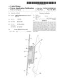
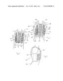
[0015] FIGS. 1, 2 and 3 are respectively a front, rear view and side view of the outer surface of cooling vest of the present invention once it has been applied and fastened on the torso of a wearer;
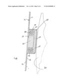
[0016] FIG. 4 is a detail transverse section through a pocket on the inside of the lining;
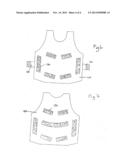
[0017] FIG. 5 is a diagrammatic view of the inside of view of the vests, in a direction at right angles to the view shown in FIG. 4;
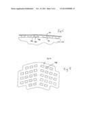
[0018] FIGS. 6 and 7 are a diagrammatic outside view of a front and back removable cooling liner of the invention; and
[0019] FIG. 8 is a diagrammatic inside view of a similar cooling liner;
[0020] Referring now to FIGS. 1 to 3 there is shown an article of clothing of the invention being a cooling vest 100 as worn on the torso 102 of the wearer. The vest 100 comprises a front panel 104, a rear panel 106 and two side panels 108 (only one shown) connecting them together. The panels 104 and 106 comprise cooling lining of the invention.
[0021] Each cooling lining comprises an inner part 112 and an outer part 114 (best shown in FIG. 4). The outer part 114 consists of a heat resistant, fireproof outer layer 116. A semi permeable membrane in the form of a moulded fabric 118 forms the inner part 114. This fabric 118 is bonded to the outer layer 116 in any convenient manner. The moulded fabric 116 is moulded into a number of pockets 120.
[0022] The moulded fabric from which the pockets 120 are made which is semipermeable to water and water vapour. Each pocket 120 is in the form of a receptacle having a rear wall 122 constituted by a portion of the outer part 114, a front wall 124 and side walls 126.
[0023] A layer 128, which comprises an insulating material, such as neoprene, and which is of the same shape as the front wall, is placed against the inside surface of the front wall 124 of the pocket 120. A central, structural support part 130 made from a lightweight heat resistant, fireproof block of the same shape but smaller size as the pocket is positioned centrally in each pocket 120 between the layer 128 and the rear wall 122. An annular surrounding chamber 132 is formed below the layer 128 between the sides of the support part 130 and the sidewalls 126 of the pocket 120. Beads 134 of a hydrophillic, water absorption compound are placed into and substantially fill the annular chamber 132.
[0024] The central support part 130, being a structural support, in combination with the insulation layer 128 ensure that the pockets 120 maintain their form. Consequently the side walls 126 of the pockets 120 are relatively taut and run perpendicularly to the rear wall 122 of the pocket 120.
[0025] As can be seen in FIGS. 1 and 2, the pockets 120 are formed in three vertical columns 136, 138 and 140 each in a tyre tread like pattern. The central column 138 comprises a number of central triangular pockets 142 between outside trapezoidal pockets 144. The outer columns 136 and 140 comprise generally quadrangular shaped pockets 144 arranged in rows sloping upwardly toward the central column 138.
[0026] The columns of pockets 120 extend vertically on the front 104 and rear panels 106. The pockets 120 run virtually the majority of the longitudinal length of the front panels 104 and rear panels 106 of the cooling vest 100. The spaces between the columns form main channels 148 which extend substantially vertically the entire length of the vest 100. Smaller vertical channels 150 extend between the centre pockets of each column form subsidiary vertical channels 152. Transverse upwardly sloping channels 156 are formed between the upper and lower pockets and these join the vertical channels 152.
[0027] It will be appreciated that the channels are defined by the side walls 126 of the pockets 120.
[0028] By having the pockets 120 and channels there is created a lattice forming a convection chamber through which air can circulate and can escape through the upper ends of the linings 100 forming the vest.
[0029] The insulating material 128 ensures that little or no heat is transferred from the body 160 of the wearer through the front walls 124 of the pockets 120. Thus heat produced by the wearer's body 160 is forced into the channels between the pockets 120. AS the temperature of the wearer's body 160 increases so air is forced to move through the lattice of channels and the hot air will cause convection in the channels 148 and 152.
[0030] The sidewalls 126 of the moulded pockets 120 are made from a material which allows air and water to pass therethrough. This ensures that the hot air in the channels warms the hydrophillic material 132, which in turn causes the water stored in the hydrophillic material 132 to heat up and to be released as water vapour from the pockets 120 into the channel lattice.
[0031] The phase change cools the area around the hydrophillic substance 132 which in turn cools the air in the channels. As the hydrophillic material 132 is capable of storing large quantities of water, the cooling caused by the phase change can continue for a significant period of time.
[0032] In use, the water is applied to the cooling vest 102. The cooling vest may be submerged in water. Alternatively water may be poured over the outer surface 116 or between the inner surface 112 of the cooling linings 100 and the wearer's torso 160. The water is absorbed by the hydrophillic water absorbing compound 134 in the pockets 120 forming a cooling chamber. As an insulation layer 128 is placed between the front wall 124 of the cooling chamber 120 the heat produced by the wearer's body 160 will not cause the water retained in the hydrophillic water absorption compound 134 to evaporate immediately.
[0033] The convection channels 148, 150, 152 formed between the sidewalls 126 of the cooling chambers 120 allow air to move thermodynamically into the predominantly vertical convection channels 148 and 150 having the beneficial effects of flue type stacks, which allow for significant air movement. As the air comes into contact with the outer side walls 126 of the cooling chambers constituted by the pockets 120, which side walls are semipermeable to water, small amounts of water in vapour form are released through the outer walls 126 of the cooling chambers in to the lattice of convection channels. The water transferred into the convection channels cools the hot air rising towards the top of the front and rear panels allowing the linings 100 to cool the wearer.
[0034] The rigidity of the supports 130 is key to maintaining the shape of the lattice and consequently allowing the airflow in the cooling channel lattice.
[0035] By using the tyre tread pattern as discussed above, we have found that the most beneficial amount of cooling is obtained relative to the amount of water stored in the hydrophillic material 132.
[0036] The cooling linings 100 for use in military situations require that the inner surfaces 112 are made from cotton and therefore the pockets 120, which are accordingly made from cotton have to be stitched on to the inner surface 112 of the front and rear portions 104 and 106 of the cooling linings 100 which may also comprise cotton.
[0037] By using cooling vests 100 as described in this specification, military personnel and the like could be kept cooler for extended periods especially when in very hot conditions such as those experienced in a desert or tropical area. Furthermore the personnel will not be tempted to relieve the discomfort caused by the heat by removing the flak jacket which would put them at risk.
[0038] In a modification, a cooling liner is provided which is a pair of separate front and rear members 160 and 162. The members may be of any desired shape capable of fitting comfortably on the wearer. The construction of the members is generally the same as that of the front and rear panels described above; each with inner and outer members 164 and 166 and having pockets 168 formed on the inside member. Side straps 170 are provided to hold the parts together. On the outside member 166 there are provided Velcro® strips 172 in any desired pattern. These members are intended for use with a conventional flak jacket (not shown) Which has been modified by being provided with corresponding Velcro® strips to hold the members in position. Thus the soldier can apply the cooling liner to the inside of the flak jacket when he had to operate under hot conditions. But when on operations on a cool day the soldier can remove one or both of the cooling liner thereby reducing the weight of the clothing that he is wearing.
[0039] The separate liners may be of different shapes as shown in FIG. 8. The pattern of the pockets 168 and lattice arrangement may vary as desired for example also as shown in FIG. 8.
[0040] This invention is not limited to the precise construction details as hereinbefore described with reference to the accompanying illustrations. For example the cooling pockets 120 and channels 50 could run along the side portions 18 of the cooling linings 100. Different materials may be provided so long as the side walls 126 of the pockets 120 are semi-permeable to water and water vapour. The pocket arrangement may utilise a greater number of smaller pockets than that as shown in the accompanying illustrations. Further the pocket arrangement may not be in the form similar to that of a tyre tread as shown in FIGS. 1 and 2. The neck portion may be in the V shape and not in a rounded neck configuration. The layout may differ according to the specific gender for whom the linings is manufactured and according to the size of the wearer's torso. If desired only one separate cooling liner, i.e. the front or rear part may be used. Instead of side straps for holding the separate members together, other mechanical fastening means may be provided such zips, buttons or press studs.
User Contributions:
Comment about this patent or add new information about this topic:
Images included with this patent application:
 |  |
 |  |
 |
| Similar patent applications: | |
| Date | Title |
|---|---|
| 2013-12-19 | Cooling device for vehicles and method for controlling and/or regulating a cooling device |
| 2011-05-05 | Cooling apparatus and method for cooling holders |
| 2012-09-27 | Apparatus and method for cooling and liquefying a fluid |
| 2012-11-15 | Cooling clothing system and method for use of same |
| 2013-10-03 | System and method for cooling electrical components |
| New patent applications in this class: | |
| Date | Title |
|---|---|
| 2017-08-17 | Cooling and hydrating containers and methods of use |
| 2017-08-17 | Air-conditioned clothing adapted to helmet |
| 2016-05-12 | Air distribution system for individual cooling |
| 2016-02-04 | Evaporative structures, particularly for body cooling |
| 2016-01-14 | Personal cooling assembly |
| Top Inventors for class "Refrigeration" | |
| Rank | Inventor's name |
|---|---|
| 1 | Michael F. Taras |
| 2 | Alexander Lifson |
| 3 | Koji Yamashita |
| 4 | Hiroyuki Morimoto |
| 5 | Patrick J. Boarman |