Patent application title: FAST SETTLING CONCENTRATION TANK FOR SEWAGE IN GANGUE
Inventors:
Muqing Su (Xiamen City, CN)
IPC8 Class: AE03F510FI
USPC Class:
210521
Class name: Liquid purification or separation gravitational separator superposed compartments or baffles, e.g., parallel plate type
Publication date: 2013-11-07
Patent application number: 20130292326
Abstract:
A fast settling concentration tank for sewage in gangue includes an outer
cylinder and an inner cylinder connected in the outer cylinder by a first
bracket. The upper end of the inner cylinder is a sewage inlet. A baffle
plate is provided in the middle of the inner cylinder by a second
bracket. A feeding gap is formed between the edge of the baffle plate and
the inner wall of the inner cylinder. At least one annular return plate
is fixed on the outer wall of the inner cylinder. An overflow gap is
formed between the outer edge of the return plate and the inner wall of
the outer cylinder. A residue outlet is formed at the lower portion of
the outer cylinder. An overflow tank is formed at the upper end of the
outer cylinder. The overflow outlet of the overflow tank is separated
from the sewage inlet.Claims:
1. A fast settling concentration tank for sewage in gangue, comprising an
outer cylinder and an inner cylinder sleeved inside the outer cylinder by
a first bracket, the inner cylinder having a sewage inlet at an upper end
thereof, a baffle plate provided in a middle of the inner cylinder by a
second bracket, a feeding gap formed between an edge of the baffle plate
and an inner wall of the inner cylinder, at least one annular return
plate fixed on an outer wall of the inner cylinder, an overflow gap
formed between an outer edge of the annular return plate and an inner
wall of the outer cylinder, a residue outlet formed by tapering a
diameter of a lower portion of the outer cylinder, an overflow tank
formed at an upper end of the outer cylinder, the overflow outlet of the
overflow tank being separated from the sewage inlet.
2. The fast settling concentration tank for sewage in gangue as claimed in claim 1, wherein the baffle plate has an arc shape which has a high middle portion and a lower edge, and the baffle plate has a diameter which is a half of a diameter of the inner cylinder.
3. The fast settling concentration tank for sewage in gangue as claimed in claim 1, wherein the annular return plate is inclined at an angle of 30 degrees relative to a horizontal plane.
4. The fast settling concentration tank for sewage in gangue as claimed in claim 1, wherein the first bracket is composed of a plurality of connecting rods, the overflow outlet is located at an outer wall of the overflow tank, and the residue outlet has a diameter which is a quarter of a diameter of the inner cylinder.
5. The fast settling concentration tank for sewage in gangue as claimed in claim 1, wherein two annular return plates are fixed on the outer wall of the inner cylinder, one is fixed at a lower end of the inner cylinder and the other is fixed at a middle section of the inner cylinder.
Description:
BACKGROUND OF THE INVENTION
[0001] 1. Field of the Invention
[0002] The present invention relates to a settling concentration technique for sewage in gangue, and more particularly to a fast settling concentration tank for sewage in gangue.
[0003] 2. Description of the Prior Art
[0004] A conventional sewage treatment system for metal mine and mineral separation comprises a settling pool, a rake frame, a transmission mechanism, a lift mechanism, a feeding mechanism and a discharge mechanism. When it is used to treat sewage, the sewage in the gangue is drained to a concentration pool through a feeding mechanism. The concentration pool is added with Aluminum Oxide to form mud. The rake frame is lowered to the concentration pool through the lift mechanism. The rake frame is used to stir the mud in the concentration pool through the transmission mechanism. The slag in the mud is settled to the lower portion of the concentration pool by gravity and drained through the discharge mechanism. The separation water is at the upper portion of the concentration pool and overflows.
[0005] This treatment system has many shortcomings, occupying a lot of space of the concentration pool, a large investment, inconvenient operation, lower treatment efficiency, and the like. Accordingly, the inventor of the present invention has devoted himself based on his many years of practical experiences to solve these problems.
SUMMARY OF THE INVENTION
[0006] The primary object of the present invention is to a fast settling concentration tank for sewage in gangue. The present invention has the advantages of simple structure, low cost, convenient operation, low failure rate, high treatment efficiency and adjustable manufacture dimensions according to the production capacity of a user.
[0007] In order to achieve the aforesaid object, the fast settling concentration tank for sewage in gangue of the present invention comprises an outer cylinder and an inner cylinder sleeved inside the outer cylinder by a first bracket. The inner cylinder has a sewage inlet at an upper end thereof. A baffle plate is provided in the middle of the inner cylinder by a second bracket. A feeding gap is formed between the edge of the baffle plate and the inner wall of the inner cylinder. At least one annular return plate is fixed on the outer wall of the inner cylinder. An overflow gap is formed between the outer edge of the annular return plate and the inner wall of the outer cylinder. A residue outlet is formed by tapering the diameter of a lower portion of the outer cylinder. An overflow tank is formed at an upper end of the outer cylinder. The overflow outlet of the overflow tank is separated from the sewage inlet.
[0008] Preferably, the baffle plate has an arc shape which has a high middle portion and a lower edge, and the diameter of the baffle plate is a half of the diameter of the inner cylinder.
[0009] Preferably, the annular return plate is inclined at an angle of 30 degrees relative to a horizontal plane.
[0010] Preferably, the first bracket is composed of a plurality of connecting rods, the overflow outlet is located at the outer wall of the overflow tank, and the diameter of the is residue outlet is a quarter of the diameter of the inner cylinder.
[0011] Preferably, two annular return plates are fixed on the outer wall of the inner cylinder, one is fixed at the lower end of the inner cylinder and the other is fixed at the middle section of the inner cylinder.
[0012] The baffle plate divides the inner cylinder into two sections, one section above the baffle plate as a feeding baffle plate area and the other section under the baffle plate to the residue outlet of the outer cylinder as a mud settling area. Between the inner cylinder and the outer cylinder is a static clean water area.
[0013] When the present invention is applied to a sewage treatment, the sewage in gangue is and added with Aluminum Oxide and then stirred to form mud. After that, the mud is sent to the fast settling concentration tank of the present invention by a mud pump. The mud flows to the feeding baffle area of the inner cylinder through the sewage inlet. The baffle plate is to decelerate and disperse the mud. The mud enters the mud settling area through the feeding gap. The sludge is stopped in the mud settling area by the return plate by way of settling of specific gravity. The slag drops to the bottom of the outer cylinder and drains from the residue outlet. The water level of the static clean water area ascends to the overflow outlet at the upper end of the outer cylinder, and then the clean water overflows.
[0014] Accordingly, the concentration of the slag drained from one concentration tank can be 40% to 60%. Through more concentration tanks, the water quality of the purified is more stable and better. Through a clean water pipe, the water can be reused. The clean water tank can be used as a high level pool. The slag is dehydrated through a press or a belt-type hydroextrator, so that the gangue can be reuse to achieve no waste mine clean production.
[0015] The invention has the advantages of simple structure, low cost, convenient operation, low failure rate, high treatment efficiency, less space occupied, automation, high quality of the circulation water, high treatment efficiency, and adjustable manufacture dimensions according to the production capacity of a user.
BRIEF DESCRIPTION OF THE DRAWINGS
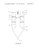
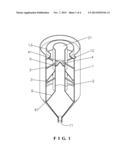
[0016] FIG. 1 is a perspective view of the present invention;
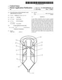
[0017] FIG. 2 is an axial sectional view of the present invention;
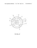
[0018] FIG. 3 is a top view of the present invention; and
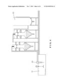
[0019] FIG. 4 is a schematic view of the present invention applied to a sewage treatment system.
DETAILED DESCRIPTION OF THE PREFERRED EMBODIMENTS
[0020] Embodiments of the present invention will now be described, by way of example only, with reference to the accompanying drawings.
[0021] As shown in FIG. 1 to FIG. 4, the present invention disclosures a fast settling concentration tank for sewage in gangue. The fast settling concentration tank comprises an outer cylinder 1 and an inner cylinder 2 sleeved inside the outer cylinder 1 by a first bracket 3. The first bracket 3 is composed of a plurality of connecting rods to provide a support and retaining effect, which doesn't reduce the static clean water area to ensure the cleaning effect. The upper end of the inner cylinder 2 is a sewage inlet 21. A baffle plate 4 is provided in the middle of the inner cylinder 2 by a second bracket 5. A feeding gap 41 is formed between the edge of the baffle plate 4 and the inner wall of the inner cylinder 2. The second bracket 5 is composed of a plurality of connecting rods to provide a support and retaining effect, which doesn't reduce the passage (the feeding gap 41) between the feeding baffle area and the mud settling area to ensure the cleaning effect. Preferably, the baffle plate 4 has an arc shape which has a high middle portion and a lower edge. Preferably, the diameter of the baffle plate 4 is a half of the diameter of the inner cylinder 2, such that the baffle plate 4 provides a better baffle effect. At least one annular return plate 6 is fixed on the outer wall of the inner cylinder 2. This embodiment has two annular return plates 6, one is fixed at the lower end of the inner cylinder 2 and the other is fixed at the middle section of the inner cylinder 2. An overflow gap 61 is formed between the outer edge of each annular return plate 6 and the inner wall of the outer cylinder 1. Preferably, the annular return plate 6 is inclined at an angle of 30 degrees relative to a horizontal plane, so that the mud can flow back well to prevent slag from exiting through the overflow outlet 12.
[0022] A residue outlet 11 is formed by tapering the diameter of the lower portion of the outer cylinder 1. The diameter of the residue outlet 11 is a quarter of the diameter of the inner cylinder 2, such that the settling time can be controlled well to enhance the concentration efficiency. An overflow tank 13 is formed at the upper end of the outer is cylinder 1. The overflow outlet 12 of the overflow tank 13 is separated from the sewage inlet 21. In order to separate the slag well to enhance the water quality from the overflow outlet 12, in the embodiment the overflow outlet 12 is located at the outer wall of the overflow tank 13.
[0023] The baffle plate 4 of the present invention divides the inner cylinder 2 into two sections, one section above the baffle plate 4 as a feeding baffle plate area and the other section under the baffle plate 4 to the residue outlet of the outer cylinder 1 as a mud settling area. Between the inner cylinder 2 and the outer cylinder 1 is a static clean water area. As shown in FIG. 4, when the present invention is applied to a sewage treatment, two concentration tanks are connected.
[0024] When in use, the sewage in gangue is drained into a gangue pool 10 and added with Aluminum Oxide and then stirred to form mud. After that, the mud is sent to the fast settling concentration tank of the present invention by a mud pump 20. The mud flows to the feeding baffle area of the inner cylinder 2 through the sewage inlet 21. The baffle plate 4 is to decelerate and disperse the mud. The mud enters the mud settling area through the feeding gap 41. The sludge is stopped in the mud settling area by the return plate 6 by way of settling of specific gravity. The slag drops to the bottom of the outer cylinder 1 and drains from the residue outlet 11. The concentration of the slag drained from the first concentration tank can be 40% to 60%, and the water enters the static clean water area through the overflow gap 61. The water level of the static clean water area ascends to the overflow outlet 12 at the upper end of the outer cylinder 1, and then the clean water overflows. The clean water drained from the first concentration tank naturally flows to the second concentration tank for a second settling concentration by the same principle of the first tank. The clean water flows to the bottom of a clean water tank 30 through the pipe pressure. The water quality of the purified water from the top or the middle of the tank is stable and better. Through a clean water pipe, the water can be reused. The clean water tank 30 can be used as a high level pool. The slag is dehydrated through a press or a belt-type hydroextrator, so that the gangue can be reuse to achieve no waste mine clean production.
[0025] Although particular embodiments of the present invention have been described in detail for purposes of illustration, various modifications and enhancements may be made without departing from the spirit and scope of the present invention. Accordingly, the present invention is not to be limited except as by the appended is claims.
User Contributions:
Comment about this patent or add new information about this topic:
Images included with this patent application:
 |  |
 |  |
 |
| Similar patent applications: | |
| Date | Title |
|---|---|
| 2010-07-15 | Wastewater concentrator |
| 2011-06-16 | Anti-clogging drainage inlet |
| 2010-12-02 | Apparatus and method for concentrating a fluid |
| 2011-01-27 | Fluid concentrator |
| 2012-02-02 | Strainer for a bilge pump |
| New patent applications in this class: | |
| Date | Title |
|---|---|
| 2015-11-05 | Partition for limiting a clarification chamber of a small sewage treatment plant |
| 2015-04-30 | Article and apparatus for enhancing the coalescence of a dispersed phase from a continuous phase in an emulsion |
| 2014-03-27 | Sludge protector canopy baffle system |
| 2013-11-07 | Coalescencer separator for a mixture of immiscible phases with different specific density |
| 2013-07-04 | Density baffle for clarifier tank |
| Top Inventors for class "Liquid purification or separation" | |
| Rank | Inventor's name |
|---|---|
| 1 | Robert W. Childers |
| 2 | Joseph A. King |
| 3 | Martin T. Gerber |
| 4 | John R. Hacker |
| 5 | Rodolfo Roger |