Patent application title: PACKER, SEALING SYSTEM AND METHOD OF SEALING
Inventors:
Bennett M. Richard (Kingwood, TX, US)
Assignees:
BAKER HUGHES INCORPORATED
IPC8 Class: AE21B3312FI
USPC Class:
166387
Class name: Processes placing or shifting well part with sealing feature (e.g., packer)
Publication date: 2013-10-24
Patent application number: 20130277068
Abstract:
A sealing system includes, a body, at least one swellable member in
operable communication with the body configured to swell into sealing
engagement with a structure proximate the body, and at least one shape
memory member in operable communication with the body and configured to
increase at least one dimension thereof in response to exposure to
transition stimulus to cause the at least one shape memory member to
contact both the body and the structure, the at least one shape memory
member also configured to support the at least one swellable member
against pressure urging it to move relative to at least one of the body
and the structure.Claims:
1. A sealing system comprising: a body; at least one swellable member in
operable communication with the body configured to swell into sealing
engagement with a structure proximate the body; and at least one shape
memory member in operable communication with the body being configured to
increase at least one dimension thereof in response to exposure to
transition stimulus to cause the at least one shape memory member to
contact the structure, the at least one shape memory member also being
configured to support the at least one swellable member against pressure
urging it to move relative to at least one of the body and the structure.
2. The sealing system of claim 1, wherein the body is tubular.
3. The sealing system of claim 1, wherein the at least one swellable member and the at least one shape memory member are positioned within an annular space between the body and the structure.
4. The sealing system of claim 1, wherein the structure is a borehole.
5. The sealing system of claim 1, wherein the at least one swellable member is polymeric.
6. The sealing system of claim 1, wherein the at least one shape memory member is foam.
7. The sealing system of claim 1, wherein the at least one shape memory member is polymeric.
8. The sealing system of claim 1, wherein the at least one swellable member is at least two swellable members and the at least one shape memory member is positioned longitudinally between the at least two swellable members.
9. The sealing system of claim 1, wherein the at least one shape memory member is at least two shape memory members and the at least one swellable member is positioned longitudinally between the at least two shape memory members.
10. The sealing system of claim 1, wherein the transition stimulus is an environment anticipated to exist downhole or via intervention.
11. The sealing system of claim 1, wherein the at least one swellable member is configured to swell in response to exposure to an environment anticipated to exist downhole or via intervention.
12. A method of sealing a body to a structure, comprising: positioning a body proximate a structure; swelling a swellable member disposed at the body into engagement with the structure; altering dimensions of a shape memory member disposed at the body into engagement with the structure; and sealing the body to the structure.
13. The method of sealing the body to the structure of claim 12, wherein the positioning the body includes running the body into a borehole.
14. The method of sealing the body to the structure of claim 12, wherein the swelling of the swellable member is in response to exposing the swellable member to downhole conditions or by intervention means.
15. The method of sealing the body to the structure of claim 12, wherein the altering dimensions of a shape memory member is in response to exposure of the shape memory member to downhole conditions or by intervention means.
16. The method of sealing the body to the structure of claim 12, further comprising supporting the swellable member against extrusion with the shape memory member.
17. A packer comprising: a tubular positionable within a borehole; a plurality of swellable members disposed around the tubular being configured to swell into sealing engagement with the borehole; and a plurality of shape memory members disposed around the tubular in a longitudinally alternating arrangement with the plurality of swellable members configured to become compressed between the tubular and the borehole after altering dimensions thereof.
Description:
BACKGROUND
[0001] Almost all tubular systems at some time need to employ seals against unwanted fluid flow. For example, in the carbon sequestration, hydrocarbon recovery and water well industries, when attempting to seal annular spaces cement is sometimes pumped into the annular space and left to harden. This method often works well as long as flow of the cement to all the desired locations within the annular space is not disrupted. These and other industries employing tubular systems however are always receptive to alternate systems and methods of creating seals.
BRIEF DESCRIPTION
[0002] Disclosed herein is a sealing system. The system includes, a body, at least one swellable member in operable communication with the body configured to swell into sealing engagement with a structure proximate the body, and at least one shape memory member in operable communication with the body and configured to increase at least one dimension thereof in response to exposure to transition stimulus to cause the at least one shape memory member to contact both the body and the structure, the at least one shape memory member also configured to support the at least one swellable member against pressure urging it to move relative to at least one of the body and the structure.
[0003] Further disclosed herein is a method of sealing a body to a structure. The method includes, positioning a body proximate a structure, swelling a swellable member disposed at the body into engagement with the structure, altering dimensions of a shape memory member disposed at the body into engagement with the structure, and sealing the body to the structure.
[0004] Further disclosed herein is a packer. The packer includes, a tubular positionable within a borehole, a plurality of swellable members disposed around the tubular and configured to swell into sealing engagement with the borehole, and a plurality of shape memory members disposed around the tubular in a longitudinally alternating arrangement with the plurality of swellable members configured to become compressed between the tubular and the borehole after altering dimensions thereof.
BRIEF DESCRIPTION OF THE DRAWINGS
[0005] The following descriptions should not be considered limiting in any way. With reference to the accompanying drawings, like elements are numbered alike:
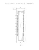
[0006] FIG. 1 depicts a cross sectional view of a sealing system disclosed herein;
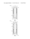
[0007] FIG. 2 depicts a cross sectional view of an alternate embodiment of a sealing system disclosed herein; and
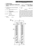
[0008] FIG. 3 depicts a cross sectional view of another alternate embodiment of a sealing system disclosed herein.
DETAILED DESCRIPTION
[0009] A detailed description of one or more embodiments of the disclosed apparatus and method are presented herein by way of exemplification and not limitation with reference to the Figures.
[0010] Referring to FIGS. 1 and 2, embodiments of a sealing system disclosed herein are illustrated at 10. The sealing system 10 includes, a body 14, illustrated in these embodiments as a tubular, a swellable member 18 positioned around the body 14, and a shape memory member 22 also positioned around the body 14. The body 14, the swellable member 18 and the shape memory member 22 of the sealing system 10 are deployable as a subassembly. The sealing system 10 can be positioned proximate a structure 26, such as within a borehole in an earth formation when used in the downhole industry, for example, or in a wellbore in a hydrocarbon recovery operation. The swellable member 18 is swellable upon exposure to environments that can be artificially produced, through intervention, for example, or are naturally occurring in a location wherein the system 10 is to be deployed. The swelling of the swellable member 18 being sufficient to cause sealing of the swellable member 18 to the structure 26. The shape memory member 22 is configured to alter a shape thereof upon exposure to a transition stimulus (e.g., temperature, electromagnetic radiation, electrical current, magnetic field, pH, etc.). The shape memory member 22 is configured to initially have clearance between the system 10 and the structure 26 but to come in contact with the structure 26 due to a dimension 30 thereof increasing upon exposure to the transition stimulus.
[0011] In the embodiments illustrated in the Figures the swellable member 18 and the shape memory member 22 are both positioned in an annular space 34 defined between the body 14 and the structure 26. The swellable member 18 sealably engages with the structure 26 upon swelling thereof. Although the swellable member 18 may be constructed of various materials, polymeric materials have been shown to swell a substantial amount and have the ability to conform to irregular surfaces such as may exist on the structure 26 if the structure 26 is a borehole in an earth formation, for example. Such conformability is advantageous for sealing. The large amount of swelling that may occur however also results in a weakening of the material such that it may be susceptible to extrusion and damage due to forces acting thereon such as in response to a pressure differential across the swellable member 18. Positioning the shape memory member 22 proximate the swellable member 18 allows the shape memory member 22 to serve as a dam to support the swellable member 18 against extrusion. By having the shape memory member 22 span the same dimension (the radial extent of the annular space 34 in these embodiments) as the swellable member 18, there is no gap left between the shape memory member 22 and the structure 26 through which the swellable member 18 is able to extrude. Additionally, compression of the shape memory member 22 between the body 14 and the structure 26 provides stored energy engagement therewith thereby increasing extrusion forces supportable by the shape memory member 22.
[0012] Several materials have been found that exhibit shape memory characteristics, and as such could be employed in the shape memory member 22. Polymeric foam is one such material. Polymeric foam has been found to be able to significantly alter dimensions thereof in response to exposure to specific transition stimulus, and as such is a good candidate for usage in the shape memory member 22. Some such foam, however, have an open cell structure that can permit permeation of fluids therethrough. The combination of the swellable member 18 and the shape memory member 22 of the system 10 disclosed herein together provide benefits that neither can provide alone. The swellable member 18 provides an effective seal to prevent flow of fluid thereby while the shape memory member 22 provides structural support to the swellable member 18 to prevent extrusion and damage thereto that if allowed to occur could allow fluid leakage thereby.
[0013] Referring to FIG. 3, an alternate embodiment of a sealing system disclosed herein is illustrated at 110. The system 110 differs from the system 10 in the number of swellable members 18 and the number of shape memory members 22 employed. Although the illustration shows four of the swellable members 18 and four of the shape memory members 22 used in the system 110 it should be understood that any practical number and alternating variations of the swellable members 18 and the shape memory members 22 could be used. There are a few advantages of employing a plurality of the members 18 and 22. One advantage is that of redundancy. That is, if one of the members 18, 22 were to fail the others can maintain full sealing and supporting functionality of the system 110. Another benefit is an increase in differential pressure that can be maintained over the sealing system 110 over the sealing system 10. Additionally, since some of the swellable members 18 have one of the shape memory members 22 located on both longitudinal sides thereof, bidirectional support is provided to those particular swellable members 18.
[0014] While the invention has been described with reference to an exemplary embodiment or embodiments, it will be understood by those skilled in the art that various changes may be made and equivalents may be substituted for elements thereof without departing from the scope of the invention. In addition, many modifications may be made to adapt a particular situation or material to the teachings of the invention without departing from the essential scope thereof. Therefore, it is intended that the invention not be limited to the particular embodiment disclosed as the best mode contemplated for carrying out this invention, but that the invention will include all embodiments falling within the scope of the claims. Also, in the drawings and the description, there have been disclosed exemplary embodiments of the invention and, although specific terms may have been employed, they are unless otherwise stated used in a generic and descriptive sense only and not for purposes of limitation, the scope of the invention therefore not being so limited. Moreover, the use of the terms first, second, etc. do not denote any order or importance, but rather the terms first, second, etc. are used to distinguish one element from another. Furthermore, the use of the terms a, an, etc. do not denote a limitation of quantity, but rather denote the presence of at least one of the referenced item.
User Contributions:
Comment about this patent or add new information about this topic:
Images included with this patent application:
 |  |
 |
| Similar patent applications: | |
| Date | Title |
|---|---|
| 2013-12-26 | Downhole debris removal tool and methods of using same |
| 2013-12-26 | Long lateral completion system and method |
| 2013-12-19 | Diverter cover assembly and methods of use |
| 2013-12-12 | Jumper tube locking assembly and method |
| 2013-12-26 | Upper mast fixture for positioning tubular and method |
| New patent applications in this class: | |
| Date | Title |
|---|---|
| 2022-05-05 | Controlled deformation and shape recovery of packing elements |
| 2022-05-05 | Packers |
| 2019-05-16 | Flow-through wellbore isolation device |
| 2019-05-16 | Wellbore isolation devices with degradable non-metallic components |
| 2018-01-25 | Wellbore isolation devices and methods of use |
| New patent applications from these inventors: | |
| Date | Title |
|---|---|
| 2017-05-18 | Disintegrable and conformable metallic seal, and method of making the same |
| 2017-01-26 | Surface texturing to increase lateral coefficient of friction |
| 2015-12-17 | Borehole shut-in system with pressure interrogation for non-penetrated borehole barriers |
| 2015-12-10 | Refracturing an already fractured borehole |
| 2015-12-10 | Beaded matrix and method of producing the same |
| Top Inventors for class "Wells" | |
| Rank | Inventor's name |
|---|---|
| 1 | Michael L. Fripp |
| 2 | Jean Marc Lopez |
| 3 | Michael H. Johnson |
| 4 | Jørgen Hallundbaek |
| 5 | Dennis P. Nguyen |