Patent application title: Grouting Cabin Structure of a Grouted Connection in a Foundation of an Offshore Wind Turbine Generator
Inventors:
Wei Li (Hangzhou, CN)
Yongming Zheng (Hangzhou, CN)
Young Zhou (Hangzhou, CN)
Shengxiao Zhao (Hangzhou, CN)
Yingchun Zhuang (Hangzhou, CN)
Caiyun Huan (Hangzhou, CN)
Na Lv (Hangzhou, CN)
Assignees:
Hydrochina Huadong Engineering Corporation
IPC8 Class: AE02B1700FI
USPC Class:
405225
Class name: Marine structure or fabrication thereof with anchoring of structure to marine floor by grouting preformed structure
Publication date: 2013-10-03
Patent application number: 20130259581
Abstract:
A grouting cabin structure of a grouted connection for use in a
foundation of an offshore wind turbine generator is described. The
structure includes a pile, a sleeve which is coaxial with said pile and
installed outside said pile, and a first grouting exhaust port and a
first connection port for a grouting pipe provided at an upper part and a
lower part of said sleeve. An enclosed cabin of a barrel form is arranged
in a gap between said pile and said sleeve, said enclosed cabin is formed
by an internal wall of said cabin and said sleeve, a second connection
port for the grouting pipe and a second grouting exhaust port are
provided at a lower and an upper pat of said enclosed cabin,
respectively; the cabin and pile form a first grouting space and said
cabin and said sleeve forms a second grouting space.Claims:
1. A grouting cabin structure of a grouted connection for use in a
foundation of an offshore wind turbine generator, the structure
comprising: a pile; a sleeve which is coaxial with said pile and
installed outside said pile; and a first grouting exhaust port and a
first connection port for a grouting pipe provided at an upper part and a
lower part of said sleeve, respectively; wherein an enclosed cabin of a
barrel form is arranged in a gap between said pile and said sleeve and is
concentric and coaxial with them; wherein said enclosed cabin is formed
by an internal wall of said cabin and said sleeve; wherein a second
connection port for the grouting pipe and a second grouting exhaust port
are provided at a lower and an upper part of said enclosed cabin,
respectively; and wherein a gap between said internal wall of said cabin
and an external wall of said pile forms a first grouting space and a gap
between said internal wall of said cabin and said sleeve forms a second
grouting space.
2. The structure according to claim 1, wherein the structure comprises a plurality of said enclosed cabins.
3. The structure according to claim 1, wherein a thickness of the internal wall of said cabin is 2 mm˜T/5, wherein T refers to a thickness of a wall of said sleeve.
4. The structure according to claim 2, wherein a thickness of the internal wall of said cabin is 2 mm˜T/5, wherein T refers to a thickness of a wall of said sleeve.
5. The structure according to claim 1, wherein a first set of one or more shear keys are arranged on an external wall of said pile, a second set of one or more shear keys are arranged on an internal wall of said cabin and facing said pile, wherein said first set of shear keys and said second set of shear keys arranged in a staggered way.
6. The structure according to claim 2, wherein a first set of one or more shear keys are arranged on an external wall of said pile, a second set of one or more shear keys are arranged on an internal wall of said cabin and facing said pile, wherein said first set of shear keys and said second set of shear keys arranged in a staggered way.
Description:
TECHNICAL FIELD
[0001] The present disclosure relates to a grouting cabin structure of a grouted connection for use in a foundation of an offshore wind turbine generator. The structure is suitable for use in offshore wind power industry.
BACKGROUND
[0002] At present, structures for foundations of offshore wind turbine generators usually employ grouted connections. For example, for a mono-pile foundation, a tower is connected with a pile via a grouted connection; for a tripod foundation and jacket foundation, a jacket is connected with piles via a grouted connection between pile sleeves and piles.
[0003] In practical implementation, performance of grouted connections can be improved by enhancing the strength of the grouting material and improving grouting techniques, and structural designs of grouted connections also play an important role. The roughness of pipe walls impacts the friction between the pipe and the grout; shear keys may enhance mechanical bond forces. However, all these stress modes are passive. Therefore, it is desired to enhance the bearing capacity of grouted connections by means of active holding actions of pre-stresses.
SUMMARY
[0004] To solve one or more of the above mentioned problems, the present disclosure provides a grouting cabin structure of a grouted connection for use in a foundation of an offshore wind turbine generator (WTG). By arranging an enclosed cabin at a grouted connection section and by means of grouting and pressurized grouting, an active holding force within the grouted connection section can be generated and, as a result, the bearing capacity of the grouted connection section can be enhanced.
[0005] The present disclosure provides a grouting cabin structure of a grouted connection for use in a foundation of an offshore wind turbine generator (WTG), the structure comprising a pile (2), a sleeve (1) which is coaxial with said pile (2) and installed outside said pile (2), a first grouting exhaust (5-1) and a first connection port (7-1) for a grouting pipe provided at an upper part and a lower part of said sleeve (1) respectively. An enclosed cabin of a barrel form is provided in a gap between said pile (2) and said sleeve (1) and is concentric and coaxial with them. Said enclosed cabin is formed by an internal wall (3) of said cabin and said sleeve (1). A second connection port (7-2) for a grouting pipe and a second grouting exhaust port (5-2) are provided at a lower part and an upper part of the enclosed cabin, hence close to a side of said sleeve (1). A gap between the internal wall (3) of the said cabin and an external wall of said pile (2) forms a first grouting space (6) and a gap between said internal wall (3) of said cabin and said sleeve (1) forms a second grouting space (4).
[0006] The grouting cabin structure may comprise a plurality of said enclosed cabins, which may he arranged in intervals.
[0007] In the grouting cabin structure, a thickness of an internal wall (3) of said cabin may be 2 mm˜T/5, wherein T refers to a thickness of a wall of said sleeve (1).
[0008] In the grouting cabin structure, a first set of one or more shear keys (8) may be arranged on an external wall of said pile (2), and a second set of one or more shear keys (3-1) may he arranged on an internal wall (3) of said cabin at a side facing said pile (2). Said first set of shear keys (8) and said second set of shear keys (3-1) may be arranged in a staggered way.
[0009] The grouting cabin structure provided by the present disclosure feature at least the following advantages: By arranging an enclosed cabin in a grouted connection section and by means of grouting and pressurized grouting in said cabin, active holding forces (pre-stresses, including pre-stress due to expansion of grouting materials) can be generated within the grouted connection section between the internal wall of the cabin and the external wall of the pile; as a result, the performance of the grouted connection section can be enhanced.
BRIEF DESCRIPTION OF THE DRAWINGS
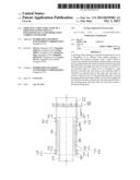
[0010] FIG. 1 shows a grouting cabin structure for use in a mono-pile foundation.
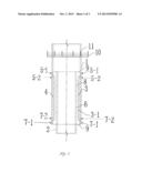
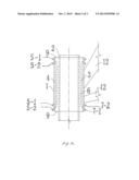
[0011] FIG. 2. shows another grouting cabin structure for use in a tripod jacket foundation.
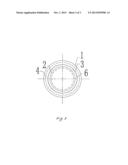
[0012] FIG. 3. is a cross-section view of the grouting cabin structure shown in FIG. 1.
DETAILED DESCRIPTION OF PREFERRED EMBODIMENTS
Embodiment 1
[0013] As shown in FIG. 1 and FIG. 3, the grouting cabin structure comprises a pile (2) and a sleeve (1) which is coaxial with said pile (2) and installed outside said pile (2), a grouting exhaust port (5-1) and a connection port (7-1) for a grouting pipe provided at an upper part and a lower part of said sleeve (1), respectively. An enclosed cabin of a barrel form is provided in a gap between said pile (2) and said sleeve (1) and is concentric and coaxial with them; said enclosed cabin is formed by an internal wall (3) of said cabin, said sleeve (1), and an upper and a lower end plates (9). A second connection port (7-2) for a grouting pipe and a second grouting exhaust port (5-2) are provided for said enclosed cabin and are arranged respectively at a lower and an upper parts of the cabin respectively, thus close to a side of said sleeve (1). A gap between said internal wall (3) of said cabin and an external wall of said pile (2) forms a first grouting space (6) and a gap between said internal wall (3) of said cabin and said sleeve (1) forms a second grouting space (4). A first set of one or more shear keys (8) are arranged on an external wall of said pile (2), and a second set of one or more shear keys (3-1) are arranged on said internal wall (3) of said cabin and facing said pile (2). Said first set of shear keys (8) and said second set of shear keys (3-1) arranged in a staggered way. (Said internal wall (3) of said cabin are preferably thick enough so that said second set of shear keys may be arranged.) Said enclosed cabin and said shear keys operate in coordination.
[0014] Where necessary, partitioned design may be employed for the enclosed cabin based on optimization calculations. That is to say, a plurality of said enclosed cabins may be provided in intervals. A thickness of said internal wall (3) of said cabin is 2 mm˜T/5, wherein T refers to a thickness of a well of said sleeve (1), and the parameters should be selected based on optimization as required in practical design.
[0015] It is advantageous to add expansion agent to grouting materials so as to enhance the effect of pre-stresses due to expansion.
[0016] In this embodiment, said sleeve (1) may be connected to a tower (11) of the wind turbine generator via a flange (10).
[0017] In this embodiment, a connection between said enclosed cabin and said sleeve (1) may be prefabricated in a factory. After said pile (2) is inserted into said sleeve (1), they are concentric and coaxial with each other.
[0018] During construction, the following process may be employed: Firstly, grouting said first grouting space (6) between said internal wall (3) of said cabin and an external wall of said pile (2); then grouting said second grouting space (4) in said cabin; closing the grouting exhaust port when mortar spills out; continuing with grouting to enhance the pressure in said enclosed cabin (by increasing pressure) until the pressure in said enclosed cabin reaches a predefined value. (The expansion effects of grouting materials comprising expansion agents on pre-stresses and the decay of pre-stresses after a still period should be considered. The actual value of the pressure should be determined based on test data or test results.)
[0019] When the pressure in said enclosed cabin reaches the predefined value, stop grouting and close said connection port of the grouting pipe. At this time, said enclosed cabin provides an active holding action (viz. pre-stress) to said first grouting space (6) and said pile (2).
Embodiment 2
[0020] Referring to FIG. 2, a jacket foundation comprises a pile sleeve (1), a support structure (12), a jacket structure (not shown) which is connected to a main column (not shown). Said jacket foundation provides a support for a tower for the wind turbine generator and other components arranged above. This embodiment is also applicable to tripod and multiple-pile jacket foundations. Other components of this embodiment are the same as those of Embodiment 1.
User Contributions:
Comment about this patent or add new information about this topic:
| People who visited this patent also read: | |
| Patent application number | Title |
|---|---|
| 20200364623 | CALCIUM CARBONATE SCALE PREDICTION AND INHIBITION IN HYDROCARBON WELLS USING MACHINE LEARNING |
| 20200364622 | SYSTEMS AND METHODS FOR DATA COLLECTION AND ANALYSIS AT THE EDGE |
| 20200364621 | GRID CARD (OR GEO TAG) |
| 20200364620 | Machine Learning Model Evaluation in Cyber Defense |
| 20200364619 | SYSTEM AND METHOD FOR DIACHRONIC MACHINE LEARNING ARCHITECTURE |
Images included with this patent application:
 |  |
 |  |
| Similar patent applications: | |
| Date | Title |
|---|---|
| 2014-02-20 | Shaft construction in the earth and method thereof |
| 2013-12-05 | Non-welded metal foundation |
| 2014-02-06 | Winch boom and method for trenchless replacement |
| 2014-02-27 | Pile with low noise generation during driving |
| 2013-10-10 | Magnetic wave generator |
| New patent applications in this class: | |
| Date | Title |
|---|---|
| 2017-08-17 | Foundation of an offshore structure |
| 2014-11-06 | Jacket for offshore structure |
| 2014-06-12 | System and method for undersea micropile deployment |
| 2013-11-14 | Wind turbine foundation |
| 2012-09-27 | Method, apparatus and system for attaching an anchor member to a floor of a body of water |
| New patent applications from these inventors: | |
| Date | Title |
|---|---|
| 2022-09-15 | Method, apparatus and device for parallel execution of smart contract, and medium |
| 2022-07-14 | Method and system for active failure recovery of single node improved based on pbft algorithm, computer device and storage medium |
| 2016-03-17 | Integrating operating systems |
| 2015-12-31 | Wind turbine generator foundation with pressure-dispersive high strength pre-stressed anchors |
| 2013-06-13 | Making a payment using a payment plug-in |
| Top Inventors for class "Hydraulic and earth engineering" | |
| Rank | Inventor's name |
|---|---|
| 1 | Joop Roodenburg |
| 2 | Thomas P. Taylor |
| 3 | Michael Tjader |
| 4 | Keith K. Millheim |
| 5 | John G. Oldsen |