Patent application title: ASSEMBLY FOR CONNECTING A BOOT TO A SKI, AND AN ADAPTER TO BE USED IN SAID ASSEMBLY
Inventors:
Even Wøllo (Naersnes, NO)
Thomas Holm (Oslo, NO)
Thomas Holm (Oslo, NO)
Øyvar Svendsen (Oslo, NO)
Aksel Pettersen (Probak, NO)
Assignees:
ROTTEFELLA AS
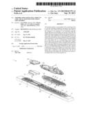
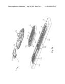
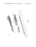
IPC8 Class: AA63C900FI
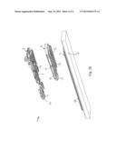
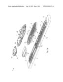
USPC Class:
280611
Class name: Skates shoe attaching means ski fasteners
Publication date: 2013-09-19
Patent application number: 20130241179
Abstract:
The invention relates to an assembly (1) for connecting a boot to a ski
(2), including a binding (3) arranged to be connected to the boot, and a
section (4) of the top surface (5) of the ski (2) arranged to be
connected to an essentially plate-like adapter (6) between the binding
(3) and the section (4), the adapter (6) being arranged to increase the
distance between at least a part of the underside (7) of the binding (3)
and the top surface (5) of the ski (2). A first locking device (9) is
arranged on the underside (7) of the binding (3) for locking the binding
(3) to the adapter (6) via a corresponding second locking device (10) on
the top side (11) of the adapter (6). Furthermore, a third locking device
(13) is arranged on the underside (12) of the adapter (6) for locking the
adapter (6) to the section (4) via a corresponding fourth locking device
(14). The first locking device (9) on the binding (3) corresponds in
addition to the fourth locking device (14) on the section (4) in order to
permit direct connection of the binding (3) to the ski (2) without the
use of the adapter (6). The invention also relates to an adapter (6) for
use in the assembly (1).Claims:
1. An assembly for connecting a boot to a ski, including a binding
arranged to be connected to the boot, and a section of the top surface of
the ski arranged to be connected to an essentially plate-like adapter
between the binding and the section, the adapter being arranged to
increase the distance between at least a part of the underside of the
binding and the top surface of the ski, comprising: a first locking
device arranged on the underside of the binding for locking the binding
to the adapter via a corresponding second locking device on the top side
of the adapter; that a third locking device arranged on the underside of
the adapter for locking the adapter to the section via a corresponding
fourth locking device, the first locking device on the binding
corresponding in addition to the fourth locking device on the section in
order to permit direct connection of the binding to the ski without the
use of the adapter, the adapter including corresponding sliding grooves
and locking catches for slide-guiding to a fastening position via said
sliding grooves, in order to permit locking in the sliding direction by
means of snap engagement via said locking catches.
2. The assembly according to claim 1, wherein the fastening position between the adapter and the section is adjustable in the longitudinal direction of the ski, a plurality of locking notches being provided along the length of the section for locking in a corresponding number of fastening positions.
3. The assembly according to claim 2, wherein the fastening position between the binding and the adapter is fixed and cannot be adjusted.
4. The assembly according to claim 1 further comprising including a separate adapter for connection between the section and a separately arranged heel piece of the binding, the adapter having an essentially identical thickness along its longitudinal direction.
5. The assembly according to claim 1 wherein the adapter has a steadily diminishing thickness or wedge shape along its longitudinal direction, and diminishing from a forward part of the adapter which corresponds to a forward part of the binding, the wedge shape allowing connection of the separately arranged heel piece of the binding directly on the section without the use of adapter.
6. The assembly according to claim 1 wherein on the underside of the adapter there is provided at least one weakened portion extending transverse to the longitudinal direction of the adapter to facilitate the bending motion of the ski in its longitudinal direction.
7. The assembly according to claim 1 wherein on each side of the long side of the adapter there is arranged an edge extending in the longitudinal direction which projects sideways beyond the width of the section, a longitudinal groove being provided in the edge for sliding accommodation of a corresponding longitudinal edge on each of the respective sides of the section.
8. The assembly according to claim 1 wherein a number of weight-saving cut-outs are provided in the adapter, and where X-shaped reinforcing ribs are arranged in the cut-outs.
9. The assembly according to claim 1 wherein the adapter is made of plastic.
10. The assembly according to claim 1 wherein the section is of plastic and is integrally configured with the top surface of the ski.
11. The adapter for use in an assembly as disclosed in claim 1.
Description:
[0001] The present invention relates to an assembly for connecting a boot
to a ski, and more specifically it relates an assembly as disclosed in
the preamble of claim 1. The invention further relates to an adapter for
use in the assembly, as disclosed in the preamble of claim 14.
[0002] Different skiers have different individual preferences as regards the positioning of the binding in relation to the ski, and thus the positioning of the skier's boot and foot during skiing. Such preferences may relate to the height of the skier's boot above ground level, for example, in order to avoid the boot coming into contact with the ground during skating or when turning. Further preferences may be the heel-toe angle where the skier's heel and toe lie at different vertical levels, or the edging angle where the external is and the internal long side of the binding lie at different vertical levels.
[0003] A spacer for use between a cross-country binding and a ski is previously known from EP 2108413 A1, where the cross-country binding is attached to the ski via bolts or screws passed through the ski binding and the spacer. The spacer in EP 2108413 A1 may have a heel-toe angle as can be seen, inter alia, from FIG. 1.
[0004] From WO 2005/113081 A1, which belongs to the Applicant, there is previously known a system for mounting a cross-country or telemark binding directly to a ski without the use of screws or the like, the mounting plate being glued to the ski, where the binding is slide-guided and snapped into place at the desired position on the mounting plate, and where the binding can later easily be removed or adjusted to a different desired position by means of the same slide-guiding and snap-locking principle. The system described in WO 2005/113081 A1 is known as the NIS system, where NIS stands for Nordic Integrated System.
[0005] A problem with the system described in EP 2108413 A1 is that it is very fiddly to remove the spacer, to adjust the position of the spacer and thus the position of the binding on the ski, or to replace the spacer with another spacer with different user properties/configuration. Drilling new holes for a new position on the ski might also impair the strength of the ski and the use properties of the ski might be altered.
[0006] The present invention seeks to remedy the aforementioned or other disadvantages or drawbacks by means of an assembly having the features disclosed in the characterising clause of claims 1 and 14, respectively. An object of the invention is thus to provide an assembly including a binding, an adapter/spacer and a ski, where the user can easily switch between different adapters or use the binding and the ski without the use of an adapter.
[0007] Advantageous embodiments of the invention are set forth in the dependent claims.
[0008] In the following description, non-limiting embodiments of the invention are described with reference to the appended drawings, wherein
[0009] FIGS. 1a and 1b are two perspective views, obliquely from above and obliquely from below respectively, of a first embodiment of the assembly according to the invention, with two planar adapters for the binding and heel piece respectively; and
[0010] FIGS. 2a and 2b are two perspective views, obliquely from above and obliquely from below respectively, of a second embodiment according to the invention, with one wedge-shaped adapter for the binding.
[0011] With reference to the figures, an assembly 1 is shown for connecting a boot to a ski 2, including a binding 3 arranged to be connected to the boot, and a section 4 of the top surface 5 of the ski 2 arranged to be connected to an essentially plate-like adapter 6 between the binding 3 and the section 4, the adapter 6 being arranged to increase the distance between at least a part of the underside 7 of the binding 3 and the top surface 5 of the ski 2.
[0012] A first locking device 9 is arranged on the underside 7 of the binding 3 for locking the binding 3 to the adapter 6 via a corresponding second locking device 10 on the top side 11 of the adapter 6. Furthermore, a third locking device 13 is arranged on the underside 12 of the adapter 6 for locking the adapter 6 to the section 4 via a corresponding fourth locking device 14. The first locking device 9 on the binding 3 corresponds in addition to the fourth locking device 14 on the section 4 in order to permit direct connection of the binding 3 to the ski 2 without the use of the adapter 6.
[0013] The locking devices 9, 10, 13, 14 advantageously include corresponding sliding grooves and locking catches for slide-guiding to a fastening position via said sliding groove, whereafter locking in the sliding direction takes place by snap engagement via said locking catches.
[0014] The fastening position between the adapter 6 and the section 4 is advantageously adjustable in the longitudinal direction of the ski 2, a plurality of locking notches being provided along the length of the section 4 for locking in a corresponding number of fastening positions. However, the fastening position between the binding 3 and the adapter 6 is advantageously fixed and cannot be adjusted.
[0015] In the embodiment shown in FIG. 1, the assembly 1 advantageously includes a separate adapter 15 for connection between the section 4 and a separately arranged heel piece 16 of the binding 3, the adapter 6 having an essentially identical thickness along its longitudinal direction.
[0016] In the embodiment shown in FIGS. 2a and 2b, the adapter 6 advantageously has a steadily diminishing thickness or wedge shape along its longitudinal direction (toe-heel angle), and diminishing from a forward part of the adapter 6 which corresponds to a forward part of the binding 3, the wedge shape allowing connection of the separately arranged heel piece 16 of the binding directly on the section 4 without the use of adapter 15.
[0017] On the underside 12 of the adapter 6 there is advantageously provided at least one weakened portion 17, 18 extending transverse to the longitudinal direction of the adapter 6 to facilitate the bending motion of the ski 2 in its longitudinal direction.
[0018] On each side of the long side of the adapter 6 there is advantageously arranged an edge 19 extending in the longitudinal direction which projects sideways beyond the width of the section 4, a longitudinal groove being provided in the edge 19 for sliding accommodation of a corresponding longitudinal edge 20 on each of the respective sides of the section 4.
[0019] Weight-saving cut-outs are advantageously provided in the adapter 6, where X-shaped reinforcing ribs 21 are arranged in the cut-outs. Furthermore, the adapter 6 is advantageously made of plastic.
[0020] The section 4 is advantageously integrally configured with the ski 2, for example, glued to the top surface of the ski, and of the NIS type as described in WO 2005/113081 A1, belonging to the Applicant, where the different fastening and engaging surfaces between the binding 3 and the section 4 are described in detail.
[0021] To release the locking of the catches, there is advantageously provided a suitable, separate (non-illustrated) tool with an end for insertion into a depression or a hole 22 arranged in a top surface of each respective locking catch, the locking catch being flipped up from its locking engagement by tilting the tool. Alternatively, an ordinary, suitable screwdriver with a flat head can be used.
[0022] The present invention is not limited to the embodiments illustrated and described here, but can be varied within the scope of the attached claims.
User Contributions:
Comment about this patent or add new information about this topic:
| People who visited this patent also read: | |
| Patent application number | Title |
|---|---|
| 20140090757 | EMULSION EXPLOSIVE SENSITISING |
| 20140090756 | COMPOSITIONS HAVING ALUMINUM PARTICLES DISPERSED IN A CONTINUOUS PHASE |
| 20140090755 | ABRASION RESISTANT STEEL PLATE OR STEEL SHEET EXCELLENT IN RESISTANCE TO STRESS CORROSION CRACKING AND METHOD FOR MANUFACTURING THE SAME |
| 20140090754 | Multimedia Quench System and Process |
| 20140090753 | METHOD FOR SOLUTION HEAT TREATED ALLOY COMPONENTS |
Images included with this patent application:
 |  |
 |  |
 |
| Similar patent applications: | |
| Date | Title |
|---|---|
| 2013-11-07 | Support of an axle transmission in the rear region of a passenger vehicle |
| 2013-11-07 | Container for receiving and carrying elongate objects |
| 2013-10-31 | Skate suspension system and method of assembly |
| 2013-11-07 | Seat tube assembly for a bicycle or the like |
| 2013-02-14 | Ice hockey runner-blade assembly |
| New patent applications in this class: | |
| Date | Title |
|---|---|
| 2016-03-31 | Heel-piece for binding a boot on a gliding board |
| 2015-04-16 | Ski boot frame |
| 2015-02-12 | Method for providing components made of composite material for a snowboard binding |
| 2015-01-15 | Splitboard binding apparatus |
| 2014-07-31 | Boot binding system with foot latch pedal |
| New patent applications from these inventors: | |
| Date | Title |
|---|---|
| 2015-11-19 | Ski binding |
| 2015-10-01 | Sole for ski boot |
| Top Inventors for class "Land vehicles" | |
| Rank | Inventor's name |
|---|---|
| 1 | Osamu Fukawatase |
| 2 | Christopher P. D'Aluisio |
| 3 | Richard W. Mccoy |
| 4 | Jun Yeol Choi |
| 5 | Yusuke Fujiwara |