Patent application title: Central Multi-level Unrestricted Air Flow System
Inventors:
William J. Warren (Addison, TX, US)
IPC8 Class: AF24H900FI
USPC Class:
454284
Class name: Ventilation having inlet airway including specific air distributor (e.g., register, etc.)
Publication date: 2013-08-29
Patent application number: 20130225062
Abstract:
A heater device to provide heated fluid at predetermined levels may
include a heat generating housing to generate the heated fluid and a heat
distribution housing to receive the heated fluid and to distribute the
heated fluid at the predetermined levels. The heat distribution housing
may include graduated vents to distribute the heated fluid. The vents may
be vertically adjustable. The vents may be horizontally adjustable. The
vents may be connected heat generation housing with a flexible tube. The
vents may be directly connected to a heat generating device. The heat
generating housing may be a common heat generating housing to at least
two heat distribution housings.Claims:
1) A heater device to provide heated fluid at predetermined levels,
comprising: a single central heat generating housing to generate the
heated fluid; a plurality of central heat distribution housing to receive
the heated fluid from a single central heat generating housing and to
distribute the heated fluid at the predetermined levels; wherein the
plurality of central heat distribution housings includes graduated vents
to distribute the heated fluid.
2) A heater device to provide heated fluid at predetermined levels as in claim 1, wherein the vents are vertically adjustable.
3) A heater device to provide heated fluid at predetermined levels as in claim 1, wherein the vents are horizontally adjustable.
4) A heater device to provide heated fluid at predetermined levels as in claim 1, wherein the vents are connected to the single central heat generation housing with a flexible tube.
5) A heater device to provide heated fluid at predetermined levels as in claim 1, wherein the vents are directly connected to the single central heat generating device.
6) A heater device to provide heated fluid at predetermined levels as in claim 1, wherein the single central heat generating housing is a common heat generating housing to at least two heat distribution housings.
Description:
RELATED APPLICATIONS
[0001] The present application is a continuation in part (CIP) of the parent application with a Ser. No. 13/405,266 which was filed on Feb. 25, 2012.
FIELD OF THE INVENTION
[0002] The present invention relates to heating devices and more particularly to a heating device having a heat generating housing and a heat distribution housing.
BACKGROUND
[0003] Heating devices are known which generally includes a heating element to heat a room or other area with little or no direction. However, these devices may be wasteful because the object of the heating device is to keep people warm. It is not necessary to heat areas where there are no human beings presently located. What is required is a heating device which can provide directional heat to the areas where people are situated.
SUMMARY
[0004] A heater device to provide heated fluid at predetermined levels may include a single central heat generating housing to generate the heated fluid and a plurality of central heat distribution housing to receive the heated fluid from a single central heat generating housing and to distribute the heated fluid at the predetermined levels.
[0005] The plurality of central heat distribution housings may include graduated vents to distribute the heated fluid.
[0006] The vents may be vertically adjustable.
[0007] The vents may be horizontally adjustable.
[0008] The vents may be connected to the single central heat generation housing with a flexible tube.
[0009] The vents may be directly connected to the single central heat generating device.
[0010] The single central heat generating housing may be a common heat generating housing to at least two heat distribution housings.
BRIEF DESCRIPTION OF THE DRAWINGS
[0011] The invention may be understood by reference to the following description taken in conjunction with the accompanying drawings, in which, like reference numerals identify like elements, and in which:
[0012] FIG. 1 illustrates an exploded view of the heater device of the present invention;
[0013] FIG. 2 illustrates a side view of the heater device of the present invention;
[0014] FIG. 3 illustrates a perspective view of the flexible tube and vent of the present invention;
[0015] FIG. 4 illustrates a front view of the heater device of the present invention;
[0016] FIG. 5 illustrates a partial view of the heat generating device of the present invention;
[0017] FIG. 6 illustrates a side view of the heat generating device of the present invention;
[0018] FIG. 7 illustrates a side view of the flexible tube and vent of the present invention;
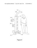
[0019] FIG. 8 illustrates another heater device of the present invention;
[0020] FIG. 9 illustrates a back view of the heater device of the present invention;
[0021] FIG. 10 illustrates a perspective view of the output tube of the present invention;
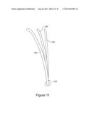
[0022] FIG. 11 illustrates a back perspective view of the output tube of the present invention;
[0023] FIG. 12 illustrates a side perspective view of the output tube of the present invention;
[0024] FIG. 13 illustrates a front view of a vent housing of the present invention;
[0025] FIG. 14 illustrates a perspective view of the graduated vent of the present invention;
[0026] FIG. 15 illustrates a back perspective view of the graduated vent of the present invention;
[0027] FIG. 16 illustrates a perspective view of the vent of the present invention;
[0028] FIG. 17 illustrates a side perspective view of the vent of the present invention;
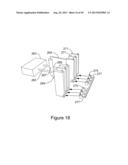
[0029] FIG. 18 illustrates a side perspective view of the vent of the present invention;
[0030] FIG. 19 illustrates a back perspective view of the vent of the present invention;
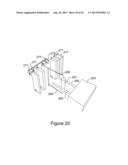
[0031] FIG. 20 illustrates a top perspective view of the vent of the present invention;
[0032] FIG. 21 illustrates a top perspective view of the vent of the present invention;
[0033] FIG. 22 illustrates a side perspective view of another vent of the present invention;
[0034] FIG. 23 illustrates a side view of the vent of the present invention;
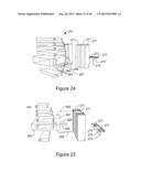
[0035] FIG. 24 illustrates a back view of the vent of the present invention;
[0036] FIG. 25 illustrates a perspective view of another heater device of the present invention;
[0037] FIG. 26 illustrates a front view of the heater device of the present invention;
[0038] FIG. 27 illustrates a side view of the heater device of the present invention;
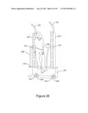
[0039] FIG. 28 illustrates an opposing side view of the heater device of the present invention
[0040] FIG. 29 illustrates another heater device of the present invention;
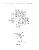
[0041] FIG. 30 illustrates a portion of the heater device of the present invention;
[0042] FIG. 31 illustrates a another inspected view of the heater device of the present invention;
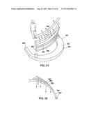
[0043] FIG. 32 illustrates another perspective view of the portion of the heater device of the present invention;
[0044] FIG. 33 illustrates another perspective view of the heater device of the present invention;
[0045] FIG. 34 illustrates another perspective view of the portion of the heater device of the present invention;
[0046] FIG. 35 illustrates a perspective view of the heater device of the present invention;
[0047] FIG. 36 illustrates another perspective view of the heater device of the present invention;
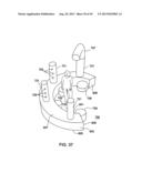
[0048] FIG. 37 illustrates another perspective view of the heater device of the present invention;
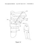
[0049] FIG. 38 illustrates another perspective view of the heater device of the present invention;
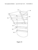
[0050] FIG. 39 illustrates another perspective view of the heater device of the present invention;
[0051] FIG. 40 illustrates another perspective view of the heater device of the present invention;
[0052] FIG. 41 illustrates a perspective view of a portion of the heater device of the present invention;
[0053] FIG. 42 illustrates a perspective view of another portion of the heater device of the present invention;
[0054] FIG. 43 illustrates a ceramic heater of the present invention;
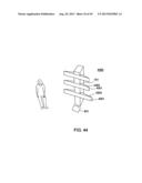
[0055] FIG. 44 illustrates another heater device of the present invention;
[0056] FIG. 45 illustrates a back perspective view of another heater device of the present invention;
[0057] FIG. 46 illustrates another back perspective view of the heater device of the present invention;
[0058] FIG. 47 illustrates a front perspective view of the heater device of the present invention;
[0059] FIG. 48 illustrates a perspective view of multiple heater devices of the present invention;
[0060] FIG. 49 illustrates a perspective view of another configuration of multiple heater devices of the present invention;
[0061] FIG. 50 illustrates a perspective view of another configuration of multiple heater devices of the present invention;
[0062] FIG. 51 illustrates a back perspective view of the heater device of the present invention;
[0063] FIG. 52 illustrates a front perspective view of the heater device of the present invention;
[0064] FIG. 53 illustrates a front perspective view of housing for the heater device of the present invention.
DETAILED DESCRIPTION
[0065] FIG. 1 illustrates an exploded view of the personal heater device 100 of the present invention, and the personal heater device 100 may include a heat generation housing 101 which may include a back wall 103 which may be connected to a top wall 107, a pair of opposing side walls 109, and a bottom wall 105 and which may include a top wall 107 which may be connected to the back wall 103, the opposing side walls 109, and the front wall 111 and may include a pair of opposing side walls 109 which may be connected to the back wall 103, the top wall 107, the front wall 111 and the bottom wall 105 and may include the bottom wall 105 which may be connected to the sidewall 109, the back wall 103 and the front wall 111 and may include the front wall 111 which may be connected to the sidewall 109 the bottom wall 105 and the top wall 107. The heat generation housing 101 maybe formed from plastic, metal, wood or other appropriate material and may include a cavity 113 which may be defined by the side wall 109, the bottom wall 105 the top wall 107 and the front wall 111. The heat generating housing 101 may be insulated, and the turbine 147 may be computer-controlled in order to adjust the amount of heat being output to the vent 141 and the tube 151.
[0066] In addition, the heater device 100 includes an output tube 151 which is connected to the top distribution wall 127 to output heated fluid from the end of the output tube 151 such as heated air to provide heat for the head including the face and hair of the user.
[0067] The personal heater device 100 may include a heat distribution housing 121 which may be mounted on the heat generation housing 101 which may include a back distribution wall 123 which may be connected to a top distribution wall 127, and a pair of opposing side distribution walls 129 and which may include a top distribution wall 127 which may be connected to the back distribution wall 123, the opposing side distribution walls 129, and the front distribution wall 129 and may include a pair of opposing side distribution walls 129 which may be connected to the back distribution wall 123, the top distribution wall 127, and the front distribution wall 129 and the bottom wall 105 and may include the bottom wall 105 which may be connected to the side distribution wall 129, the back distribution wall 123 and the front distribution wall 129 and may include the front distribution wall 129 which may be connected to the side distribution wall 129, and the top distribution wall 127. The heat distribution housing 101 maybe formed from plastic, metal, wood or other appropriate material and may include a distribution cavity 133 which may be defined by the side wall 109, the bottom wall 105 the top distribution wall 127 and the front distribution wall 129. The heating device 100 may include a ground fault indicator (GFI) switch to disconnect the heating device 100 from electricity if a ground fault is detected.
[0068] The heating device 100 may be powered either totally from a battery or maybe powered with a battery backup or may be switchable between a battery and electric power supplied from a utility such as household power. The heating device 100 may be totally battery-powered.
[0069] The front distribution wall 131 may include multiple graduated vents 141 positioned within the front distribution wall 131. Each of the graduated vents 141 may be adjustable in order to adjust the amount of heated airflow
[0070] The heat generating housing 101 may include multiple heat generating devices 143 which may include resistance wiring 145 to generate heat from electrical current such as household current or a battery and a turbine 147 which may move the generated heat and may be connected to a flexible tube which may be dedicated and connected to the turbine 147. The turbine 147 may include multiple for example 2 axial turbines connected in series. For example, the turbine 147a may be dedicated and connected to flexible tube 149a, and the turbine 147b may be dedicated and connected to the flexible tube 149b.
[0071] The turbine 147a may be vertically stacked with respect to the turbine 147b.
[0072] The turbine 147 may be directly connected to the flexible tube 149 which may be directly connected to the vent 141. Alternatively, the turbine 147 may be indirectly connected to the flexible tube 149.
[0073] The turbine 147 may be controlled by a photo electric on off switch.
[0074] The flexible tube 149a conducts the heated fluid which may be heated air to the graduated vent 141a and the flexible tube 149b conducts the heated fluid which may be heated air to the graduated vent 141b. In a similar fashion, the remaining graduated vents 141 are connected to a flexible tube 149 which is in turn connected to a dedicated turbine 147.
[0075] FIG. 2 illustrates a side view of the heater device 100 and illustrates the flexible tube 149 which may extend from the top wall 107 to the side distribution wall 129, the output tube 151 which may extend from the top distribution wall 127 and the heat generating device 143 which may be connected to the flexible tube 149.
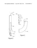
[0076] FIG. 3 illustrates a perspective view of the output tube 151 and illustrates that the output tube 151 may include a slot 153 which may cooperate with a grill 155 having graduated vents.
[0077] FIG. 4 illustrates a perspective view of the heater device 100 and illustrates that the heat generating housing 101 may include multiple heat generating devices 143 which may include resistance wiring 145 to generate heat from electrical current such as household current and a turbine 147 which may move the generated heat and may be connected to a flexible tube 149 which may be dedicated and connected to the turbine 147. For example, the turbine 147a of the heat generating device 143a may be dedicated and connected to flexible tube 149a which may be connected to the graduated vent 141a, and the turbine 147b of the heat generating device 143b may be dedicated and connected to the flexible tube 149b which may be connected to the graduated vent 141b. The flexible tube 149a conducts the heated fluid which may be heated air to the graduated vent 141a and the flexible tube 149b conducts the heated fluid which may be heated air to the graduated vent 141b. In a similar fashion, the remaining graduated vents 141 are connected to a flexible tube 149 which is in turn connected to a dedicated turbine 147.
[0078] FIG. 5 illustrates the heating housing 150 which may include a heater back wall 151 which may be connected to a heater bottom wall 153, a heater top wall 159 and a pair of opposing heater side walls 157 and may include a heater front wall 155 which may be connected to the heater back wall 151, the heater bottom wall 153 and the pair of opposing side walls 157. The heater housing may include a heater top wall 159 which may be connected to the heater back wall 151, the heater front wall 155 and the heater side wall 157. Additionally, the heater top wall may be connected to the flexible tube 149 to conduct the heat to the heater device 100 and the heater housing 150 may include a bottom wall 153 which may be connected to the heater back wall 151, the heater front wall 155 and the heater side walls 157 and which may be connected to pad feet 161 to connect to the support surface such as a floor.
[0079] The resistance wiring 145 may extend through the heater back wall 151 in order to connect to household current or other source of electricity power. The resistance wiring 145 may be connected to a photo switch in order to detect if a user is in front of the heater housing. If the user is not in front of the heater housing, the resistance wiring 145 is disconnected. In a similar fashion, the resistance wiring 145 may be connected to a switch which will disconnect the resistance wiring if the heater housing has been knocked over. Furthermore, the resistance wiring 145 may be connected to a surge protected circuit to protect the resistance wiring 145 from a surge of either current or voltage. The turbine 147 may be positioned on the heater bottom wall 153 and a aperture (not shown) may extend through the heater bottom wall 153 in order to supply fluid such as air to the turbine 147. The turbine 147 may be a fan, an axial fan, a radial fan, a compression fan, a non-compression fan, brush fan, jet engine or other appropriate type of fan.
[0080] FIG. 6 illustrates a side perspective view of the heating housing 150 and illustrates the heating housing 150 which may include a heater back wall 151 which may be connected to a heater bottom wall 153, a heater top wall 159 (not shown) and a pair of opposing heater side walls 157 and may include a heater front wall 155 (not shown) which may be connected to the heater back wall 151, the heater bottom wall 153 and the pair of opposing side walls 157. The heater housing may include a heater top wall 159 (not shown) which may be connected to the heater back wall 151, the heater front wall 155 and the heater side wall 157. Additionally, the heater top wall may be connected to the flexible tube 149 (not shown). To conduct the heat to the heater device 100 and the heater housing 150 may include a bottom wall 153 which may be connected to the heater back wall 151, the heater front wall 155 and the heater side walls 157 and which may be connected to pad feet 161 to connect to the support surface such as a floor.
[0081] The resistance wiring 145 may extend through the heater back wall 151 in order to connect to household current or other source of electricity power. The turbine 147 may be positioned on the heater bottom wall 153 and an aperture (not shown) may extend through the heater bottom wall 153 in order to supply fluid such as air to the turbine 147. The turbine 147 may be a fan, an axial fan, a radial fan, a compression fan, a non-compression fan, brush fan, jet engine or other appropriate type of fan.
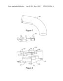
[0082] FIG. 7 illustrates a side perspective view of the output tube 151 which may be curved in order to more easily directly to the user. The output to 151 may include a graduated vent 141.
[0083] FIG. 8 illustrates a perspective view of the heater device 100 of the present invention, and the personal heater device 100 may include a heat distribution housing 121 which may be mounted on the heat generation housing 101. The heat generation housing 101 may include heater housing 150, and the heater housing 150 may be directly mounted on the distribution housing 121 in order to eliminate the flexible tube 149.
[0084] FIG. 9 illustrates a back perspective view of the heater device 100 of the present invention, and the personal heater device 100 may include a heat distribution housing 121 which may be mounted on the heat generation housing 101. The heat generation housing 101 may include heater housing 150 and the heater housing 150 may be directly mounted on the distribution housing 121 in order to eliminate the flexible tube 149.
[0085] FIG. 10 illustrates a perspective view of the output tube 152 which may include multiple output tubes 154 which may extend from the output tube 152. This aspect facilitates an uninterrupted air flow at certain stages going up the vent and therefore produces more down flow.
[0086] FIG. 11 illustrates a back perspective view of the output tube 152 which may include multiple output tubes 154 which may extend from the output tube 152.
[0087] FIG. 12 illustrates a side perspective view of the output tube 152 which may include multiple output tubes 154 which may extend from the output tube 152.
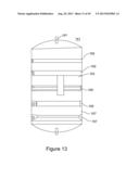
[0088] FIG. 13 illustrates a graduated vent 141 to move the direction of the fluid flow both vertically and horizontally (left to right or up and down) by rotating the graduated vent 141 on the pivot shaft 161 which cooperates with an aperture in the heating device 100 to move the direction of the fluid flow horizontally (left to right or vice versa). The pivot shafts 161 may be mounted on the top and bottom of a vent housing 167 which may be in the shape of a truncated cylinder. The graduated vent 141 may include a control arm 163 to move the direction of the fluid flow vertically (up and down) by moving the control arm 163 vertically. FIG. 13 additionally illustrates that the graduated vent 141 may include multiple fluid guides 165 positioned within the vent housing 167.
[0089] FIG. 14 illustrates a perspective side view of the graduated vent 141 and illustrates the control arm 163 and the fluid guides 165 of varying lengths and a pair of opposing connecting arms 169 to connect the fluid guides 165 and to raise and lower the fluid guides 165 in response to the up and down movement of the control arm 163.
[0090] FIG. 15 illustrates a perspective back view of the graduated vent 141 and illustrates the control arm 163 and the fluid guides 165 of varying lengths and a pair of opposing connecting arms 169 to connect the fluid guides 165 and to raise and lower the fluid guides 165 in response to the up and down movement of the control arm 163.
[0091] FIG. 16 illustrates another graduated vent 241 which may include a control arm 263 to control the fluid guides 271 to direct the fluid (air) vertically (side to side) and which may be connected to a pair of opposing side control arms 265 which may move the control cylinder 267 from side to side in response to movement of the control arm 263. The control cylinder 267 may be connected to connecting arms 269 which may be connected to a single fluid guide 271 which may be one of multiple fluid guides 271 which may be pivotably connected so that when the single fluid guide 271 is pivoted by the master control arm 263 so that the remaining fluid guides 271 pivot.
[0092] The fluid guides 271 may include a slot 272 to pivot a cylinder 275 which rotates between disks 277 which may be connected to a guide connector arm 273 which may traverse the multiple fluid guides 271 and which may be connected to the vent housing (not shown).
[0093] FIG. 18 illustrates a back view and illustrates another graduated vent 241 which may include a control arm 263 to control the fluid guides 271 to direct the fluid (air) vertically (side to side) and which may be connected to a pair of opposing side control arms 265 which may move the control cylinder 267 from side to side in response to movement of the control arm 263. The control cylinder 267 may be connected to connecting arms 269 which may be connected to a single fluid guide 271 which may be one of multiple fluid guides 271 which may be pivotably connected so that when the single fluid guide 271 is pivoted by the master control arm 263 so that the remaining fluid guides 271 pivot.
[0094] The fluid guides 271 may include a slot 272 to pivot a cylinder 275 which rotates between disks 277 which may be connected to a guide connector arm 273 which may traverse the multiple fluid guides 271 and which may be connected to the vent housing (not shown).
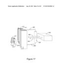
[0095] FIG. 17 illustrates a side view and illustrates another graduated vent 241 which may include a control arm 263 to control the fluid guides 271 to direct the fluid (air) vertically (side to side) and which may be connected to a pair of opposing side control arms 265 which may move the control cylinder 267 from side to side in response to movement of the control arm 263. The control cylinder 267 may be connected to connecting arms 269 which may be connected to a single fluid guide 271 which may be one of multiple fluid guides 271 which may be pivotably connected so that when the single fluid guide 271 is pivoted by the master control arm 263 so that the remaining fluid guides 271 pivot.
[0096] The fluid guides 271 may include a slot 272 to pivot a cylinder 275 which rotates between disks 277 which may be connected to a guide connector arm 273 which may traverse the multiple fluid guides 271 and which may be connected to the vent housing (not shown). The fluid guides 271 may vary in length and width and may be graduated.
[0097] FIG. 19 illustrates a side view and illustrates another graduated vent 241 which may include a control arm 263 to control the fluid guides 271 to direct the fluid (air) vertically (side to side) and which may be connected to a pair of opposing side control arms 265 which may move the control cylinder 267 from side to side in response to movement of the control arm 263. The control cylinder 267 may be connected to connecting arms 269 which may be connected to a single fluid guide 271 which may be one of multiple fluid guides 271 which may be pivotably connected so that when the single fluid guide 271 is pivoted by the master control arm 263 so that the remaining fluid guides 271 pivot.
[0098] The fluid guides 271 may include a slot 272 to pivot a cylinder 275 which rotates between disks 277 which may be connected to a guide connector arm 273 which may traverse the multiple fluid guides 271 and which may be connected to the vent housing (not shown). The fluid guides 271 may vary in length and width and may be graduated.
[0099] FIG. 19 illustrates a back view and illustrates another graduated vent 241 which may include a control arm 263 to control the fluid guides 271 to direct the fluid (air) vertically (side to side) and which may be connected to a pair of opposing side control arms 265 which may move the control cylinder 267 from side to side in response to movement of the control arm 263. The control cylinder 267 may be connected to connecting arms 269 which may be connected to a single fluid guide 271 which may be one of multiple fluid guides 271 which may be pivotably connected so that when the single fluid guide 271 is pivoted by the master control arm 263 so that the remaining fluid guides 271 pivot.
[0100] The fluid guides 271 may include a slot 272 to pivot a cylinder 275 which rotates between disks 277 which may be connected to a guide connector arm 273 which may traverse the multiple fluid guides 271 and which may be connected to the vent housing (not shown). The fluid guides 271 may vary in length and width and may be graduated.
[0101] FIG. 20 illustrates a top view and illustrates another graduated vent 241 which may include a control arm 263 to control the fluid guides 271 to direct the fluid (air) vertically (side to side) and which may be connected to a pair of opposing side control arms 265 which may move the control cylinder 267 from side to side in response to movement of the control arm 263. The control cylinder 267 may be connected to connecting arms 269 which may be connected to a single fluid guide 271 which may be one of multiple fluid guides 271 which may be pivotably connected so that when the single fluid guide 271 is pivoted by the master control arm 263 so that the remaining fluid guides 271 pivot.
[0102] The fluid guides 271 may include a slot 272 to pivot a cylinder 275 which rotates between disks 277 which may be connected to a guide connector arm 273 which may traverse the multiple fluid guides 271 and which may be connected to the vent housing (not shown). The fluid guides 271 may vary in length and width and may be graduated.
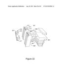
[0103] FIG. 22 illustrates a side view and illustrates another graduated vent 341 which may include a control arm 363 to control the fluid guides 271 to direct the fluid (air) vertically (side to side) and which may be connected to a pair of opposing side control arms 265 which may move the control cylinder 267 from side to side in response to movement of the control arm 263. The control cylinder 267 may be connected to connecting arms 269 which may be connected to a single fluid guide 271 which may be one of multiple fluid guides 271 which may be pivotably connected so that when the single fluid guide 271 is pivoted by the master control arm 263 so that the remaining fluid guides 271 pivot.
[0104] The fluid guides 271 may include a slot 272 to pivot a cylinder 275 which rotates between disks 277 which may be connected to a guide connector arm 273 which may traverse the multiple fluid guides 271 and which may be connected to the vent housing (not shown). The fluid guides 271 may vary in length and width and may be graduated.
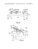
[0105] The control arm 363 additionally controls horizontal fluid guides 365 which may pivot horizontally (up and down) to direct the fluid which may be air up and down. The control arm 363 may direct the fluid both up and down and from side to side in order to provide flexibility in the direction of the fluid. The horizontal fluid guides includes pivot shaft 361 which may cooperate with the housing (not shown) and may include a curved connection arm 369 to connect the horizontal fluid guides 365 and the control arm 363 to allow the horizontal fluid guides to visit upwards and downwards in response to movement of the control arm 363.
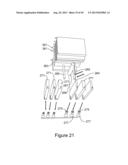
[0106] FIG. 21 illustrates a top view and illustrates another graduated vent 341 which may include a control arm 363 to control the fluid guides 271 to direct the fluid (air) vertically (side to side) and which may be connected to a pair of opposing side control arms 265 which may move the control cylinder 267 from side to side in response to movement of the control arm 263. The control cylinder 267 may be connected to connecting arms 269 which may be connected to a single fluid guide 271 which may be one of multiple fluid guides 271 which may be pivotably connected so that when the single fluid guide 271 is pivoted by the master control arm 263 so that the remaining fluid guides 271 pivot.
[0107] The fluid guides 271 may include a slot 272 to pivot a cylinder 275 which rotates between disks 277 which may be connected to a guide connector arm 273 which may traverse the multiple fluid guides 271 and which may be connected to the vent housing (not shown). The fluid guides 271 may vary in length and width and may be graduated.
[0108] The control arm 363 additionally controls horizontal fluid guides 365 which may pivot horizontally (up and down) to direct the fluid which may be air up and down. The control arm 363 may direct the fluid both up and down and from side to side in order to provide flexibility in the direction of the fluid. The horizontal fluid guides includes pivot shaft 361 which may cooperate with the housing (not shown) and may include a curved connection arm 369 to connect the horizontal fluid guides 365 and the control arm 363 to allow the horizontal fluid guides to visit upwards and downwards in response to movement of the control arm 363.
[0109] FIG. 23 illustrates a side view and illustrates another graduated vent 341 which may include a control arm 363 to control the fluid guides 271 to direct the fluid (air) vertically (side to side) and which may be connected to a pair of opposing side control arms 265 which may move the control cylinder 267 from side to side in response to movement of the control arm 263. The control cylinder 267 may be connected to connecting arms 269 which may be connected to a single fluid guide 271 which may be one of multiple fluid guides 271 which may be pivotably connected so that when the single fluid guide 271 is pivoted by the master control arm 263 so that the remaining fluid guides 271 pivot.
[0110] The fluid guides 271 may include a slot 272 to pivot a cylinder 275 which rotates between disks 277 which may be connected to a guide connector arm 273 which may traverse the multiple fluid guides 271 and which may be connected to the vent housing (not shown). The fluid guides 271 may vary in length and width and may be graduated.
[0111] The control arm 363 additionally controls horizontal fluid guides 365 which may pivot horizontally (up and down) to direct the fluid which may be air up and down. The control arm 363 may direct the fluid both up and down and from side to side in order to provide flexibility in the direction of the fluid. The horizontal fluid guides includes pivot shaft 361 which may cooperate with the housing (not shown) and may include a curved connection arm 369 to connect the horizontal fluid guides 365 and the control arm 363 to allow the horizontal fluid guides to visit upwards and downwards in response to movement of the control arm 363.
[0112] FIG. 24 illustrates a front view and illustrates another graduated vent 341 which may include a control arm 363 to control the fluid guides 271 to direct the fluid (air) vertically (side to side) and which may be connected to a pair of opposing side control arms 265 which may move the control cylinder 267 from side to side in response to movement of the control arm 263. The control cylinder 267 may be connected to connecting arms 269 which may be connected to a single fluid guide 271 which may be one of multiple fluid guides 271 which may be pivotably connected so that when the single fluid guide 271 is pivoted by the master control arm 263 so that the remaining fluid guides 271 pivot.
[0113] The fluid guides 271 may include a slot 272 to pivot a cylinder 275 which rotates between disks 277 which may be connected to a guide connector arm 273 which may traverse the multiple fluid guides 271 and which may be connected to the vent housing (not shown). The fluid guides 271 may vary in length and width and may be graduated.
[0114] The control arm 363 additionally controls horizontal fluid guides 365 which may pivot horizontally (up and down) to direct the fluid which may be air up and down. The control arm 363 may direct the fluid both up and down and from side to side in order to provide flexibility in the direction of the fluid. The horizontal fluid guides includes pivot shaft 361 which may cooperate with the housing (not shown) and may include a curved connection arm 369 to connect the horizontal fluid guides 365 and the control arm 363 to allow the horizontal fluid guides to visit upwards and downwards in response to movement of the control arm 363.
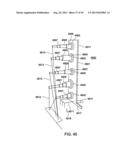
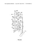
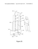
[0115] FIG. 25 illustrates multiple heat distribution housing 321 being connected to a common heat generating housing 101 and illustrates resistive wiring 145 and a turbine 147 for each of the heat distribution housing 321. Each heat distribution housing includes a vent output tube 151, graduated vent 141 and at least one flexible tube 149.
[0116] FIG. 26 illustrates multiple heat distribution housing 321 being connected to a common heat generating housing 101 and illustrates resistive wiring 145 and a turbine 147 for each of the heat distribution housing 321. Each heat distribution housing includes a vent output tube 151, graduated vent 141 and at least one flexible tube 149.
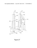
[0117] FIG. 27 illustrates multiple heat distribution housing 321 being connected to a common heat generating housing 101 and illustrates resistive wiring 145 and a turbine 147 for each of the heat distribution housing 321. Each heat distribution housing includes a vent output tube 151, graduated vent 141 and at least one flexible tube 149.
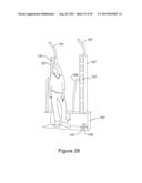
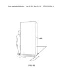
[0118] FIG. 28 illustrates multiple heat distribution housing 321 being connected to a common heat generating housing 101 and illustrates resistive wiring 145 and a turbine 147 for each of the heat distribution housing 321. Each heat distribution housing includes a vent output tube 151, graduated vent 141 and at least one flexible tube 149.
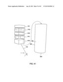
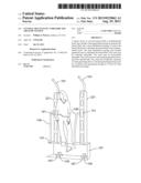
[0119] FIG. 29 illustrates an exploded view of the central heater device 500 of the present invention, and the central heater device 500 may include a central heat generation housing 501 which may include a inward curved back wall 503 (concavely curved) which may be connected to a curved top wall 507, a pair of opposing side walls 509, and a curved bottom wall 505 and which may include a curved top wall 507 which may be connected to the back wall 503, the opposing side walls 509, and the inward curved front wall 511 (concavely curved) and may include a pair of opposing side walls 509 which may be connected to the back wall 503, the top wall 507, the front wall 511 and the bottom wall 505 and may include the bottom wall 505 which may be connected to the sidewall 509, the back wall 503 and the front wall 511 and may include the front wall 511 which may be connected to the sidewall 509 the bottom wall 505 and the top wall 507. The central heat generation housing 501 maybe formed from plastic, metal, wood or other appropriate material and may include a cavity 513 which may be defined by the side wall 509, the bottom wall 505 the top wall 507 and the front wall 511. The central heat generating housing 501 may be insulated, and the turbine/motor 729 may be computer-controlled in order to adjust the amount of heat being output.
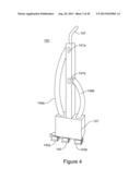
[0120] In addition, the heater device 500 includes an output tube 551 which is connected to the curved top wall 507 to output heated fluid from the end of the output tube 551 such as heated air to provide heat for the head including the face and hair of the user. The output tube 551 may be curved to correspond to the curve of the curved top wall 507 and may be supported at each end of the output tube 551, and the a first portion 553 of the output tube 551 may extend over the curved top wall 507 and a second portion 555 of the output tube 551 may extend upwards and then a third portion 557 of the output tube 551 reverse and extend over the first portion 553 of the output tube 551. This pattern may be repeated any number of times in order to provide additional coverage for the user.
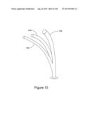
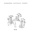
[0121] FIG. 30 illustrates a perspective view of a alternate tube design, and more particularly, FIG. 30 illustrates a central tube 561 which may be connected to the top wall 507 and which may feed a multitude of secondary tubes 563 which may extend upwards and side wards from the central tube 561 which may connect to the top wall 507.
[0122] FIG. 31 illustrates an exploded back view of the central heater device 500 of the present invention, and the central heater device 500 may include a central heat generation housing 501 which may include a inward curved back wall 503 (concavely curved) which may be connected to a curved top wall 507, a pair of opposing side walls 509, and a curved bottom wall 505 and which may include a curved top wall 507 which may be connected to the back wall 503, the opposing side walls 509, and the inward curved front wall 511 (concavely curved) and may include a pair of opposing side walls 509 which may be connected to the back wall 503, the top wall 507, the front wall 511 and the bottom wall 505 and may include the bottom wall 505 which may be connected to the sidewall 509, the back wall 503 and the front wall 511 and may include the front wall 511 which may be connected to the sidewall 509 the bottom wall 505 and the top wall 507. The central heat generation housing 501 maybe formed from plastic, metal, wood or other appropriate material and may include a cavity 513 which may be defined by the side wall 509, the bottom wall 505 the top wall 507 and the front wall 511. The central heat generating housing 501 may be insulated, and the turbine/motor 729 may be computer-controlled in order to adjust the amount of heat being generated.
[0123] In addition, the heater device 500 includes an output tube 551 which is connected to the curved top wall 507 to output heated fluid from the end of the output tube 551 such as heated air to provide heat for the head including the face and hair of the user. The output tube 551 may be curved to correspond to the curve of the curved top wall 507 and may be supported at each end of the output tube 551, and the a first portion 553 of the output tube 551 may extend over the curved top wall 507 and a second portion 555 of the output tube 551 may extend upwards and then a third portion 557 of the output tube 551 reverse and extend over the first portion 553 of the output tube 551. This pattern may be repeated any number of times in order to provide additional coverage for the user.
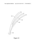
[0124] FIG. 32 illustrates a alternate tube design, and more particularly, FIG. 32 illustrates a central tube 561 which may feed a multitude of secondary tubes 563 which may extend upwards and side wards from the central tube 561.
[0125] FIG. 33 illustrates a perspective side view of the central heater device 500.
[0126] FIG. 34 illustrates a alternate tube design, and more particularly, FIG. 34 illustrates a central tube 561 which may feed a multitude of secondary tubes 563 which may extend upwards and side wards from the central tube 561.
[0127] FIG. 35 illustrates an perspective front view of the central heater device 600 of the present invention, and the central heater device 600 may include a central heat generation housing 601 which may include an inward curved back wall 603 (concavely curved) which may be connected to a curved top wall 607, a pair of opposing side walls 609, and a curved bottom wall 605 and which may include a curved top wall 607 which may be connected to the back wall 603, the opposing side walls 609, and the inward curved front wall 611 (concavely curved) and may include a pair of opposing side walls 609 which may be connected to the back wall 603, the top wall 607, the front wall 611 and the bottom wall 605 and may include the bottom wall 605 which may be connected to the sidewall 609, the back wall 603 and the front wall 611 and may include the front wall 611 which may be connected to the sidewall 609 the bottom wall 609 and the top wall 607. The central heat generation housing 601 maybe formed from plastic, metal, wood or other appropriate material and may include a cavity 613 which may be defined by the side wall 609, the bottom wall 605 the top wall 607 and the front wall 611. The central heat generating housing 601 may be insulated, and the turbine/motor 729 may be computer-controlled in order to adjust the amount of heat being output to the heat distribution housing 621. The internal surfaces of the central heat generating housing 601 may be coated with insulation in order to reduce the noise from the fan.
[0128] The central heater device 600 may include a multitude of heat distribution housings 621 which may be mounted on the central heat generation housing 601 and may extend upwards from the top surface 607, and the heat distribution housing 621 may include a back distribution wall 623 which may be connected to a top distribution wall 627, and a pair of opposing side distribution walls 629 and may include a top distribution wall 627 which may be connected to the back distribution wall 623, the opposing side distribution walls 629, and the front distribution wall 629 and may include a pair of opposing side distribution walls 629 which may be connected to the back distribution wall 623, the top distribution wall 627, and the front distribution wall 629 and may include the top wall 607 which may be connected to the side distribution wall 623, the back distribution wall 623 and the front distribution wall 629 and may include the front distribution wall 629 which may be connected to the side distribution wall 623, and the top distribution wall 627. The heat distribution housing 601 may be formed from plastic, metal, wood or other appropriate material and may include a distribution cavity 633 which may be defined by the side distribution wall 623, the top distribution wall 627 and the front distribution wall 629. The heating device 100 may include a ground fault indicator (GFI) switch to disconnect the heating device 601 from electricity if a ground fault is detected. A single output tube 631 may extend out of the top distribution wall 627 and may output heat for the user.
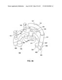
[0129] FIG. 36 illustrates an perspective front view of the central heater device 700 of the present invention, and the central heater device 700 may include a central heat generation housing 601 which may include an inward curved back wall 603 (concavely curved) which may be connected to a curved top wall 607, a pair of opposing side walls 609, and a curved bottom wall 605 and which may include a curved top wall 607 which may be connected to the back wall 603, the opposing side walls 609, and the inward curved front wall 611 (concavely curved) and may include a pair of opposing side walls 609 which may be connected to the back wall 603, the top wall 607, the front wall 611 and the bottom wall 605 and may include the bottom wall 605 which may be connected to the sidewall 609, the back wall 603 and the front wall 611 and may include the front wall 611 which may be connected to the sidewall 609 the bottom wall 609 and the top wall 607.
[0130] The central heat generation housing 601 maybe formed from plastic, metal, wood or other appropriate material and may include a cavity 613 which may be defined by the side wall 609, the bottom wall 605 the top wall 607 and the front wall 611. The central heat generating housing 601 may be insulated, and the turbine/motor 729 may be computer-controlled in order to adjust the amount of heat being output to the multitude of heat distribution housings 721.
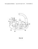
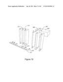
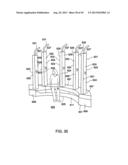
[0131] The heat distribution housings 721 may be cylinders which extend from the top wall 607 and the heat distribution housing 721 may include heat vents 725 which extend through the wall of the cylinder and may be used to allow heat to escape the heat distribution housing 721 and may include a top heat distribution tube 727 which may be directed inwards to distribute heat.
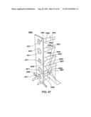
[0132] FIG. 37 illustrates an perspective side view of the central heater device 700 of the present invention, and the central heater device 700 may include a central heat generation housing 601 which may include an inward curved back wall 603 (concavely curved) which may be connected to a curved top wall 607, a pair of opposing side walls 609, and a curved bottom wall 605 and which may include a curved top wall 607 which may be connected to the back wall 603, the opposing side walls 609, and the inward curved front wall 611 (concavely curved) and may include a pair of opposing side walls 609 which may be connected to the back wall 603, the top wall 607, the front wall 611 and the bottom wall 605 and may include the bottom wall 605 which may be connected to the sidewall 609, the back wall 603 and the front wall 611 and may include the front wall 611 which may be connected to the sidewall 609 the bottom wall 609 and the top wall 607. The central heat generation housing 601 maybe formed from plastic, metal, wood or other appropriate material and may include a cavity 613 which may be defined by the side wall 609, the bottom wall 605 the top wall 607 and the front wall 611. The central heat generating housing 601 may be insulated.
[0133] The heat distribution housings 721 may be cylinders which extend from the top wall 607 and the heat distribution housing 721 may include heat vents 725 which extend through the wall of the cylinder and may be used to allow heat to escape the heat distribution housing 721 and may include a top heat distribution tube 727 which may be directed inwards to distribute heat.
[0134] FIG. 37 illustrates central motors/turbines 729 which may be positioned within the cavity 613 and may be in communication with the heat distribution housing 721 in order to move the heated fluid which may be air from the heat source (not shown) to the heat distribution housing 721.
[0135] FIG. 38 illustrates an perspective bottom view of the central heater device 700 of the present invention, and the central heater device 700 may include a central heat generation housing 601 which may include an inward curved back wall 603 (concavely curved) which may be connected to a curved top wall 607, a pair of opposing side walls 609, and a curved bottom wall 605 and which may include a curved top wall 607 which may be connected to the back wall 603, the opposing side walls 609, and the inward curved front wall 611 (concavely curved) and may include a pair of opposing side walls 609 which may be connected to the back wall 603, the top wall 607, the front wall 611 and the bottom wall 605 and may include the bottom wall 605 which may be connected to the sidewall 609, the back wall 603 and the front wall 611 and may include the front wall 611 which may be connected to the sidewall 609 the bottom wall 609 and the top wall 607. The central heat generation housing 601 maybe formed from plastic, metal, wood or other appropriate material and may include a cavity 613 which may be defined by the side wall 609, the bottom wall 605 the top wall 607 and the front wall 611. The central heat generating housing 601 may be insulated, and the turbine/motor 729 may be computer-controlled in order to adjust the amount of heat being output to the multitude of heat distribution housings 721.
[0136] The heat distribution housings 721 may be cylinders which extend from the top wall 607 and the heat distribution housing 721 may include heat vents 725 which extend through the wall of the cylinder and may be used to allow heat to escape the heat distribution housing 721 and may include a top heat distribution tube 727 which may be directed inwards to distribute heat.
[0137] FIG. 39 illustrates an perspective view of the central heater device 800 of the present invention, and the central heater device 800 may include a central heat generation housing 601 which may include an inward curved back wall 603 (concavely curved) which may be connected to a curved top wall 607, a pair of opposing side walls 609, and a curved bottom wall 605 and which may include a curved top wall 607 which may be connected to the back wall 603, the opposing side walls 609, and the inward curved front wall 611 (concavely curved) and may include a pair of opposing side walls 609 which may be connected to the back wall 603, the top wall 607, the front wall 611 and the bottom wall 605 and may include the bottom wall 605 which may be connected to the sidewall 609, the back wall 603 and the front wall 611 and may include the front wall 611 which may be connected to the sidewall 609 the bottom wall 609 and the top wall 607. The central heat generation housing 601 maybe formed from plastic, metal, wood or other appropriate material and may include a cavity 613 which may be defined by the side wall 609, the bottom wall 605 the top wall 607 and the front wall 611. The central heat generating housing 601 may be insulated, and the turbine/motor 729 may be computer-controlled in order to adjust the amount of heat being output to the multitude of heat distribution housings 721.
[0138] FIG. 39 illustrates a alternate tube design, and more particularly, FIG. 39 illustrates a central tube 561 which may feed a multitude of secondary tubes 563 which may extend upwards and side wards from the central tube 561 which may be connected to the top wall 607.
[0139] FIG. 40 illustrates an perspective view of the central heater device 800 of the present invention, and the central heater device 800 may include a central heat generation housing 601 which may include an inward curved back wall 603 (concavely curved) which may be connected to a curved top wall 607, a pair of opposing side walls 609, and a curved bottom wall 605 and which may include a curved top wall 607 which may be connected to the back wall 603, the opposing side walls 609, and the inward curved front wall 611 (concavely curved) and may include a pair of opposing side walls 609 which may be connected to the back wall 603, the top wall 607, the front wall 611 and the bottom wall 605 and may include the bottom wall 605 which may be connected to the sidewall 609, the back wall 603 and the front wall 611 and may include the front wall 611 which may be connected to the sidewall 609 the bottom wall 609 and the top wall 607. The central heat generation housing 601 maybe formed from plastic, metal, wood or other appropriate material and may include a cavity 613 which may be defined by the side wall 609, the bottom wall 605 the top wall 607 and the front wall 611. The central heat generating housing 601 may be insulated, and the turbine/motor 729 may be computer-controlled in order to adjust the amount of heat being output to the vent 141 and the multitude of heat distribution housings 721.
[0140] FIG. 40 illustrates a alternate tube design, and more particularly, FIG. 40 illustrates a central tube 561 which may feed a multitude of secondary tubes 563 which may extend upwards and side wards from the central tube 561 which may be connected to the top wall 607.
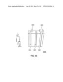
[0141] FIG. 41 illustrates a heating housing cylinder 900 which may be a hollow heating device and which may be a rectangle or other appropriate shape. The heating housing cylinder 900 may include a substantially rigid wall 902 which may define a cavity 904 which may be formed from metal, plastic or other appropriate material and may include a heat generating device 143, a first turbine 147a, a second turbine 147b, a third turbine 147c and a fourth turbine 147d which may be stacked with the heat generating device 143 and may be positioned within the cavity 904. Each of the turbines 147 may be a axial turbine, a radial turbine, a turbine fan or any propulsion device or any combination. FIG. 41 additionally illustrates a power cord 149 to power the heat generating device 143 and/or the turbine 147. Heating wires may be embedded in the ceramic plates, and the plates may be aluminum AL baffles or maybe Eistein heater.
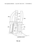
[0142] FIG. 42 illustrates a portion of the personal heater device 100 or a portion of the central heater device 600 and illustrates that the heating cylinder 900 may be directly connected to the flexible tube 149 and may be directly connected to the heat distribution housing 101. The heating cylinder 900 may be connected to a power source with Ni Crone wires, ceramic wires or maybe a Eistein heater. The heating cylinder 900 may be a rigid or flexible cylinder.
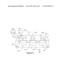
[0143] FIG. 43 illustrates a ceramic heating device 4300 which may include heat distribution grooves 4301 in order to increase the surface area of the ceramic heating device 4303 and may include aluminum wires 4303 to connect to a power supply.
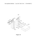
[0144] FIG. 44 illustrates another personal heating device 4300 which may include a heat distribution housing 101 which may be connected to the central heating housing 601. The heat distribution housing 601 may be coupled to the horizontal vents 4301 which may extend substantially horizontally and may include apertures 4303 to distribute the heat from the central heating housing 601.
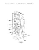
[0145] FIGS. 45-53 illustrates a heater device 4500 in accordance with the teachings of the present invention.
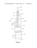
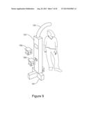
[0146] FIG. 45 illustrates a mounting wall 4501 which may include a mounting sleeve 4503 to mount the heat generating housing 4505 which may include turbine 4507 which may include a multitude of axial turbines to generate an airflow in order to propel the fluid which may be air into the room and a heat generating device 4509 which may be connected to the turbine 107 to generate heat which is transferred to the fluid to be propelled into the room and which may be connected to the mounting sleeve 4503 which may be connected to a fluid vent 4511 which may be circular, oval or other appropriate shape and may rotate in order to change the direction of the fluid flow (airflow).
[0147] The heat generating housing 4505 may be connected to wires 4513 which may be connected to a power bus 4515. Additionally, the mounting wall 4501 may include feet 4517 which may extend from the mounting wall 4501 in order to support the mounting wall 4501 on the supporting surface 4519
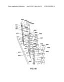
[0148] FIG. 46 illustrates a mounting wall 4501 which may include a mounting sleeve 4503 to mount the heat generating housing 4505 which may include turbine 4507 which may include a multitude of axial turbines to generate an airflow in order to propel the fluid which may be air into the room and a heat generating device 4509 which may be connected to the turbine 107 to generate heat which is transferred to the fluid to be propelled into the room and which may be connected to the mounting sleeve 4503 which may be connected to a fluid vent 4511 which may be circular, oval or other appropriate shape and may rotate in order to change the direction of the fluid flow (airflow).
[0149] The heat generating housing 4505 may be connected to wires 4513 which may be connected to a power bus 4515. Additionally, the mounting wall 4501 may include feet 4517 which may extend from the mounting wall 4501 in order to support the mounting wall 4501 on the supporting surface 4519.
[0150] FIG. 47 illustrates a mounting wall 4501 which may include a mounting sleeve 4503 to mount the heat generating housing 4505 which may include turbine 4507 which may include a multitude of axial turbines to generate an airflow in order to propel the fluid which may be air into the room and a heat generating device 4509 which may be connected to the turbine 107 to generate heat which is transferred to the fluid to be propelled into the room and which may be connected to the mounting sleeve 4503 which may be connected to a fluid vent 4511 which may be circular, oval or other appropriate shape and may rotate in order to change the direction of the fluid flow (airflow).
[0151] The heat generating housing 4505 may be connected to wires 4513 which may be connected to a power bus 4515. Additionally, the mounting wall 4501 may include feet 4517 which may extend from the mounting wall 4501 in order to support the mounting wall 4501 on the supporting surface 4519.
[0152] FIG. 47 additionally illustrates a photocell 4551 to detect an object such as a user of the heating device 4500.
[0153] FIG. 48 illustrates a multitude of the heating devices 4500 including a mounting wall 4501 which may include a mounting sleeve 4503 to mount the heat generating housing 4505 which may include turbine 4507 which may include a multitude of axial turbines to generate an airflow in order to propel the fluid which may be air into the room and a heat generating device 4509 which may be connected to the turbine 107 to generate heat which is transferred to the fluid to be propelled into the room and which may be connected to the mounting sleeve 4503 which may be connected to a fluid vent 4511 which may be circular, oval or other appropriate shape and may rotate in order to change the direction of the fluid flow (airflow).
[0154] The heat generating housing 4505 may be connected to wires 4513 which may be connected to a power bus 4515. Additionally, the mounting wall 4501 may include feet 4517 which may extend from the mounting wall 4501 in order to support the mounting wall 4501 on the supporting surface 4519.
[0155] FIG. 48 illustrates that the heater devices 4500 are substantially aligned and adjacent to another heating device 4500.
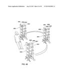
[0156] FIG. 49 illustrates that the heater devices 4500 are positioned in substantially a semi circle.
[0157] FIG. 50 illustrates a front perspective view of the heater devices 4500 being positioned substantially in a semi circle.
[0158] FIG. 51 illustrates a back perspective view of the heater device 4500 and illustrates a wire 4513 to connect to the power bus 4515.
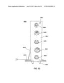
[0159] FIG. 52 illustrates a front view of the heater device 4500.
[0160] FIG. 53 illustrates a cover 45534 the heater device 4500.
[0161] While the invention is susceptible to various modifications and alternative forms, specific embodiments thereof have been shown by way of example in the drawings and are herein described in detail. It should be understood, however, that the description herein of specific embodiments is not intended to limit the invention to the particular forms disclosed.
User Contributions:
Comment about this patent or add new information about this topic:
Images included with this patent application:
 |  |
 |  |
 |  |
 |  |
 |  |
 |  |
 |  |
 |  |
 |  |
 |  |
 |  |
 |  |
 |  |
 |  |
 |  |
 |  |
 |  |
 |  |
 |  |
 |  |
 |  |
 |  |
 |  |
| Similar patent applications: | |
| Date | Title |
|---|---|
| 2014-07-24 | Controller configured to receive blower volumes for different operating modes per zones, an hvac system including the controller and a method of operating the controller |
| 2014-07-24 | Equipment rack and associated ventilation system |
| 2014-07-24 | Air flow extension system for air flow registers |
| 2014-07-24 | Automated fresh air cooling system |
| 2013-05-09 | Directed server rack air flow |
| New patent applications in this class: | |
| Date | Title |
|---|---|
| 2016-06-30 | Air discharge device and air conditioner having the same |
| 2015-10-22 | Air-conditioning unit |
| 2015-05-28 | Universal inlet duct system for side air intake equipment |
| 2015-05-21 | Decorative air conduit |
| 2015-05-21 | Air conditioning units |
| New patent applications from these inventors: | |
| Date | Title |
|---|---|
| 2013-11-28 | Exercise device |
| 2013-08-29 | Multi level unrestricted air flow system |
| 2013-07-04 | Fluid resistance device |
| Top Inventors for class "Ventilation" | |
| Rank | Inventor's name |
|---|---|
| 1 | Dariusz Krakowski |
| 2 | Paul Bryan Hoke |
| 3 | Alan L. Browne |
| 4 | Darrell Horner |
| 5 | Gregory S. Daniels |