Patent application title: Method for Replacing Weapon Rear Sight with Optics
Inventors:
Shanyao Lee (Irvine, CA, US)
Shanyao Lee (Irvine, CA, US)
IPC8 Class: AF41C2700FI
USPC Class:
42 90
Class name: Firearms implements
Publication date: 2013-08-29
Patent application number: 20130219766
Abstract:
A method and apparatus providing for the replacement of the original rear
sight of a rifle by a mounted sight, rail, or sight base, such that said
replacement is adjustable and does not interfere with the regular
function or disassembly of the rifle, especially with SKS, AK, PKM, and
other related tangent sight systems.Claims:
1. An accessory mount base for rifles comprising: A receptacle for
mounted accessories; A means for attaching said receptacle to said rifle
whereby said receptacle replaces the original rear sight of the rifle;
2. The accessory mount base from claim 1 wherein said accessory mount base further comprises a means to attach accessories to said accessory mount base;
3. The means to attach accessories from claim 2 wherein said means involves the use of a rail system.
4. The means to attach accessories from claim 2 wherein said means involves the use of an accessory plate.
5. The accessory mount base from claim 1 wherein the position of said accessory mount base can be adjusted;
6. The accessory mount base from claim 5 wherein the position of said accessory mount base can be adjusted by varying the position of a screw;
7. The screw from claim 6 wherein said screw utilizes threading to maintain the integration of two or more parts.
8. The mounted accessories from claim 1 wherein the position of said mounted accessories can be adjusted.
9. The mounted accessories from claim 1 wherein said accessory is positioned such that it is level with the line of sight of the rifle.
10. An accessory for rifles wherein said accessory attaches to said rifle by replacing the original rear sight of said rifle.
11. The accessory from claim 10 wherein said the position of said accessory can be adjusted.
12. The accessory from claim 10 wherein said accessory is positioned such that it is level with the line of sight of the rifle.
Description:
FIELD OF THE INVENTION
[0001] The application relates to a method and apparatus for replacing the original rear sight of an SKS, AK, PKM, or other related tangent sight system with another sighting system.
BACKGROUND OF THE INVENTION
[0002] 1. Prior Art
[0003] Presently, AK type rifles have been extremely popular amongst recreational shooters, hunters, militaries, security personnel, and other shooters. The popularity of such rifles is largely due to their durability, low production cost, and ease of use. However, when these rifles were originally designed, mounted sights were rarely, if ever, used. As the use of mounted optics has become more popular, different methods for mounting said optics on SKS, AK, PKM, and other related tangent sight system weapons have been employed. One popular method involves installing a side rail mount on the weapon such that the sight is attached at the side of the rifle and contorted to aid sight at the top portion of the rifle. Adversely, installing a side rail mount in this way is complicated and makes disassembling the weapon much more difficult after installation. Also, attaching the sight at this point exposes the sight to much of the kick from the weapon's firing; as such accuracy is marginal at best. Another popular method is to mount sights on the front end gas tube directly or indirectly on the same. Adversely, mounting sights in this way places the sight so far away from the shooter's eye as to make the sight difficult to operate effectively.
[0004] U.S. patent application Ser. No. 10/790,408 provides a method and apparatus for mounting rifle scopes by replacing the original rear sight of the weapon with a sight base to which various scopes may be mounted. According to this invention, the sight base and corresponding mounted scopes are unable to maintain or adjust position relative to the lateral ends of the rifle because the left/right position is maintained by the friction between certain rolling pins and corresponding holes, and is therefore unpredictable and hard for the user to control. Additionally, the position of the screws on the top of said sight base corresponds to depressions in the rear battle sight mount which forms the base of the original rear sight. This correspondence is not ideal because it requires the use of longer, less accurate screws to maintain height, one of the most important elements of sighting a weapon.
[0005] There exists a need for a method and apparatus for mounting sights onto SKS, AK, PKM, and other related tangent sight system rifles such that said method and apparatus provides for effective mounting of said sights without permanently altering the rifle that allows for a flexible, adjustable mount of the sight.
[0006] 2. Objects and Advantages
[0007] Accordingly, several objects and advantages of this invention are:
(a) to provide for the stable and effective attachment of weapon sights to the rifle; (b) to provide for the possible addition of a rail system or other mounting base that allows for attachment of various accessories; (c) to provide for stable and effective attachment of various accessories; (d) to provide for flexible adjustment of the weapon sights; (e) to provide sights at a height that allows the weapon to be used as naturally as if the shooter were looking through the original iron sight;
[0008] Further objects and advantages of this invention will become apparent from a consideration of the drawings and ensuing description.
SUMMARY OF THE INVENTION
[0009] The following summary is provided to facilitate an understanding of some of the innovative features unique to the embodiments and is not intended to be a full description. A full appreciation of the various aspects of the embodiments can be gained by taking the entire specification, claims, drawings, and abstract as a whole.
[0010] In accordance with the present invention a method and apparatus for providing for the adjustable attachment of a sight base replacing the original rear sight of SKS, AK, PKM, or other rifle.
BRIEF DESCRIPTION OF DRAWINGS
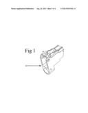
[0011] FIG. 1 is a close-up, isolated view of the rear battle sight mount, according to certain embodiments of the prior art.
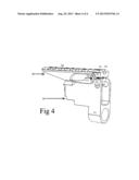
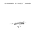
[0012] FIG. 2 is a close-up, isolated view of the accessory mount rail system, according to certain embodiments of the present invention.
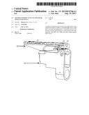
[0013] FIG. 3 is a disassembled view of the rear battle sight mount and accessory mount rail system and their corresponding integrating units, according to certain embodiments of the present invention.
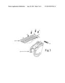
[0014] FIG. 4 is a perspective view of the assembled rear battle sight mount and accessory mount rail system together, according to certain embodiments of the present invention.
[0015] So that the manner in which the above recited features, advantages and objects of the present invention are attained and can be understood in detail, a more particular description of the invention, briefly summarized above, may be had by reference to the preferred embodiment thereof which is illustrated in the appended drawings, which drawings are incorporated as a part hereof.
[0016] It is to be noted however, that the appended drawings illustrate only a typical embodiment of this invention and are therefore not to be considered limiting of its scope, for the invention may admit to other equally effective embodiments.
DETAILED DESCRIPTION
FIGS. 1-4
[0017] With reference now to the drawings, the preferred embodiment of the alternative accessory mount according to the present invention is herein described. As can be seen in FIG. 1, rear battle sight mount 10 is attached to the rifle at attachment of rear battle sight mount to rifle 11. According to certain embodiments, rear battle sight mount 10 further comprises integration holes for side screw 12.
[0018] According to certain embodiments, as shown in FIG. 2, in the present invention, accessory mount base 20 is attached atop rear battle sight mount 10. Accessory mount base 20 further comprises integration holes for side screw 21 and accessory mount receiver 22.
[0019] According to certain embodiments, as shown in FIG. 3, in the present invention, side screw 40 is engaged through integration holes for side screw 12 and integration holes for side screw 21, thus coupling rear battle sight mount 10 and accessory mount base 20. Nut 41 engages the end of side screw 40 such as to maintain the strength and stability of the integration of rear battle sight mount 10 to accessory mount base 20. Furthermore, according to certain embodiments, front screws 31 engage integration holes for front screws 23 such that front screws 31 push against rear battle sight mount 10, further stabilizing the position of rear battle sight mount 10. Back screw 32, engages accessory mount base 20, further stabilizing the position of rear battle sight mount 10.
[0020] According to certain embodiments, as can be seen in FIG. 4, in the present invention, when front screws 23 have engaged integration holes for front screws 23, when side screw 40 has engaged rear battle sight mount 10, accessory mount base 20, and nut 41, and when back screw 32 engages accessory mount base 20, accessory mount base 20 sits atop rear battle sight mount 10.
[0021] The foregoing description of the invention has been presented for purposes of illustration and description. It is not intended to be exhaustive or to limit the invention to the precise form disclosed, and other modifications and variations may be possible in light of the above teachings. The embodiment was chosen and described in order to best explain the principles of the invention and its practical application to thereby enable others skilled in the art to best utilize the invention in various embodiments and various modifications as are suited to the particular use contemplated. It is intended that the appended claims be construed to include other alternative embodiments of the invention except insofar as limited by the prior art.
[0022] The invention may be embodied in other forms without departing from the spirit or essential characteristics thereof. The present embodiments are therefore to be considered as illustrative and not restrictive, the scope of the invention being indicated by the appended claims rather than by the foregoing description, and all changes that come within the meaning and range of equivalency of the claims are therefore intended to be embraced therein.
OPERATION
FIG. 3
[0023] As shown in FIG. 3, according to the present invention, in the preferred embodiment, rear battle sight mount 10 attaches the rifle (not shown), by at attachment of rear battle sight mount to rifle 11 such that rear battle sight mount 10 is stable on the rifle (not shown). Side screw 40 and nut 41 engage rear battle sight mount 10 and accessory mount base 20. Through varying the engagement of side screw 40 and nut 41 relative to rear battle sight mount 10 and accessory mount base 20, side screw 40 provides for adjustment of the leftright position of the accessory mount base 20 relative to rear battle sight mount 10. According to certain embodiments, front screws 31 engage integration holes for front screws 23, whereby front screws 31 push against rear battle sight mount 10, such that the angle of the line of sight relative to a line parallel to the barrel of the rifle can be adjusted. Additionally, engaging front screws 31 with integration holes for front screws 23 allows for increased stability of the positioning of the accessory mount base 20 during regular use of the rifle. According to certain embodiments, back screw 32 engages accessory mount base 20 and back screw 32 pushes against the top of rear battle sight mount 10 so as to increase the stability of accessory mount base 20 during regular use of the weapon.
[0024] According to certain embodiments, accessory mounts such as optical sights and laser sights (not shown) are attached to the top of accessory mount base 20.
CONCLUSION, RAMIFICATIONS, AND SCOPE
[0025] Thus, the reader will see that the method and apparatus will provide for the replacement of the original rear sight of the weapon with mounted sight, rail, or sight base.
[0026] While the above description contains many specifications, these should not be construed as limitations of the scope of the invention, but rather as an exemplification of a preferred embodiment of the invention. Many other variations and embodiments are possible.
[0027] Accordingly, the scope of the invention should be determined not by the embodiment illustrated, but by the appended claims and their legal equivalents.
User Contributions:
Comment about this patent or add new information about this topic:
| People who visited this patent also read: | |
| Patent application number | Title |
|---|---|
| 20170116371 | NEURAL NETWORK FOR PROCESSING APTAMER DATA |
| 20170116370 | DNA Alignment using a Hierarchical Inverted Index Table |
| 20170116369 | METHOD FOR DESIGNING OVERALL STOICHIOMETRIC CONVERSIONS AND INTERVENING METABOLIC REACTIONS |
| 20170116368 | OPTICAL RULE CHECKING FOR DETECTING AT RISK STRUCTURES FOR OVERLAY ISSUES |
| 20170116367 | ELECTROMIGRATION-AWARE INTEGRATED CIRCUIT DESIGN METHODS AND SYSTEMS |
Images included with this patent application:
 |  |
 |  |
 |
| Similar patent applications: | |
| Date | Title |
|---|---|
| 2012-05-31 | Tracking weapon health and maintenance |
| 2013-09-12 | Actuation device for adjusting or setting a parameter of an optical device including a telescopic sight |
| 2013-03-14 | Cooling of weapons with graphite foam |
| 2012-06-21 | Weapon sight light emission system |
| 2013-08-22 | Folding stock adaptor for military-style assault rifles and a method for its use |
| New patent applications in this class: | |
| Date | Title |
|---|---|
| 2022-05-05 | Configurable cable holder for firearms |
| 2019-05-16 | Universal gun rail mount for accessories |
| 2018-01-25 | Movable firearm accessory support assembly |
| 2016-12-29 | Rear sight block for ak-type rifles |
| 2016-09-01 | Mounting assembly |
| New patent applications from these inventors: | |
| Date | Title |
|---|---|
| 2015-09-10 | Precision hop-up mechanism |
| 2014-10-30 | Light intensified fiber optic sight |
| 2014-03-27 | Heat sink rail system |
| 2014-01-30 | Glock buffer |
| 2013-12-12 | Pistol belt clip |
| Top Inventors for class "Firearms" | |
| Rank | Inventor's name |
|---|---|
| 1 | Michael T. Mayberry |
| 2 | Mark C. Laney |
| 3 | Stephen P. Troy |
| 4 | Russell A. Potterfield |
| 5 | Dennis Cauley |