Patent application title: FURNITURE UNIT TO SIT-ON
Inventors:
Tadeusz Mazur (Michalowice, PL)
Assignees:
TADEUSZ MAZUR CENTRUM REHABILITACJI
IPC8 Class: AA47C318FI
USPC Class:
297135
Class name: Chairs and seats with table, desk, or easel
Publication date: 2013-08-22
Patent application number: 20130214566
Abstract:
A Furniture Unit to sit-on that comprises a frame, a seat, and a backrest
where the seat is secured to the frame or to the base of the backrest
frame using a ball joint, whereas the backrest frame is adjustable and
equipped with at least one rest element wherein the bearing of the ball
joint (A1) is secured to the seat (1), and the ball of the ball joint
(A2) is secured to the main frame (2) or to the base of the backrest
frame (3); the diameter of the ball joint (A) is smaller than 15 cm.Claims:
1. A Furniture Unit to sit-on, comprising: a frame, a seat, and a
backrest wherein the seat is secured to the frame or to a base of a
backrest frame using a ball joint having a diameter that is smaller than
15 cm, and wherein the backrest is equipped with at least one rest
element embedded in the backrest frame using a ball joint.
2. The Furniture Unit to sit-on as set forth in claim 1, wherein the backrest frame is equipped with three independent movable rest elements, and wherein a middle rest is embedded in the backrest frame using a ball joint.
3. The Furniture Unit to sit-on as set forth in claim 2, wherein each of an upper rest and a lower rest included in the movable rest elements consists of two elements situated parallel to each other and symmetrically towards the vertical axis of the backrest frame, and each of the upper rest and the lower rest element is fixed independently to the backrest frame.
4. The Furniture Unit to sit-on as set forth in claim 1, wherein the Furniture Unit is equipped with a footrest with two movable props for feet, connected with a footrest frame by a flexible joint using a crank mechanism.
5. The Furniture Unit to sit-on as set forth in claim 1, wherein a prop for the raised upper extremities is secured to the backrest frame.
6. The Furniture Unit to sit-on as set forth in claim 1, wherein armrests are fixed to the base of the backrest frame.
7. The Furniture Unit to sit-on as set forth in claim 1, wherein a top or a working surface for a PC keyboard is secured to the base of the backrest frame, and wherein the top or working surface is equipped with a fixing jib.
8. The Furniture Unit to sit-on as set forth in claim 2, wherein the Furniture Unit is equipped with a footrest with two movable props for feet, connected with the footrest frame by a flexible joint using a crank mechanism.
9. The Furniture Unit to sit-on as set forth in claim 3, wherein the Furniture Unit is equipped with a footrest with two movable props for feet, connected with the footrest frame by a flexible joint using a crank mechanism.
10. The Furniture Unit to sit-on as set forth in claim 2, wherein a prop for the raised upper extremities is secured to the backrest frame.
11. The Furniture Unit to sit-on as set forth in claim 3, wherein a prop for the raised upper extremities is secured to the backrest frame.
12. The Furniture Unit to sit-on as set forth in claim 4, wherein a prop for the raised upper extremities is secured to the backrest frame.
13. The Furniture Unit to sit-on as set forth in claim 2, wherein armrests are fixed to the base of the adjustable backrest frame.
14. The Furniture Unit to sit-on as set forth in claim 3, wherein armrests are fixed to the base of the adjustable backrest frame.
15. The Furniture Unit to sit-on as set forth in, claim 4, wherein armrests are fixed to the base of the adjustable backrest frame.
16. The Furniture Unit to sit-on as set forth in claim 5, wherein armrests are fixed to the base of the adjustable backrest frame.
17. The Furniture Unit to sit-on as set forth in claim 2, wherein a top or a working surface for a PC keyboard is secured to the base of the backrest frame, and wherein the top or working surface is equipped with a fixing jib.
18. The Furniture Unit to sit-on as set forth in claim 3, wherein a top or a working surface for a PC keyboard is secured to the base of the backrest frame, and wherein the top or working surface is equipped with a fixing jib.
19. The Furniture Unit to sit-on as set forth in claim 4, wherein a top or a working surface for a PC keyboard is secured to the base of the backrest frame, wherein the top or working surface is equipped with a fixing jib.
20. The Furniture Unit to sit-on as set forth in claim 5, wherein a top or a working surface for the PC keyboard is secured to the base of the backrest frame, and wherein the top or working surface is equipped with a fixing jib.
21. The Furniture Unit to sit-on as set forth in claim 6, wherein a top or a working surface for the PC keyboard is secured to the base of the backrest frame, and the top or working surface is equipped with the fixing jib.
Description:
[0001] The present Invention provides a furniture unit to sit on it; it is
designed for application when resting or performing office work.
[0002] One of the known solutions of such furniture units to sit-on is disclosed in the international invention description under the Patent No. WO 95/16374. It is a chair with a seat fixed to the frame in a manner permitting the frame to move in all directions. For this purpose, the seat is mounted to the frame using a spiral spring, a ball joint, or any other adequate mechanism. Such a seat is reposed on a ball-shaped head having a relatively large radius and placed within the concave bottom plane of a cylinder encompassing the entire head. The cylinder height determines the inclination angle; additionally, this angle may be properly adjusted using a screw mechanism or through the diameter of a hole in the cylinder lid. Such a chair allows for the increased mobility of the upper body part of a person working in a sitting position; it also enables the improvement of the chair's user posture. Moreover, the stimulation of the nerve at the end of the spinal column enhances the physical state.
[0003] Another known chair solution is disclosed in the invention description under the Patent No. WO 2009157148. The solution cited comprises a rocking chair equipped with a seat with a lower convex part forming a spherical surface with its central point set above the seat. The rotating rollers contacting the lower convex surface allow for the convex part to move along the spherical surface and the chair supporting part.
[0004] The hitherto used furniture units designed for sitting on allow that the following movements of the sitting person's body are possible: leaning, vibrations, rocking or driving, but the individual body parts move toward each other only accidentally.
[0005] The objective of the Invention is, on the one hand, to ensure, while sitting, the stabilization of specific body axes. On the other hand, the objective is to concurrently ensure a motion around those axes in order to enable the controlled rotational movements of torso since they determine the frequent and easy changing of the workload of articular surfaces and capsules, ligaments, and muscles.
[0006] According to the present Invention, the furniture unit to sit-on comprises a main frame, a seat, and a backrest frame. Using a ball joint, the seat is mounted either to the main frame or to the adjustable base of the backrest frame equipped with at least one backrest. The furniture unit to sit-on is characterized by a feature consisting in that a bearing of the ball joint is fixed to the seat, and the ball of the ball joint is mounted to the main frame or to the base of the backrest frame, whereas the diameter of ball joint is smaller than 15 cm.
[0007] Preferably, the backrest frame is equipped with three independent movable rest elements; the middle rest element may be embedded in the frame using a ball joint, and, additionally, both the upper and the lower rests can be made of two independent elements placed parallel toward each other and symmetrically, towards the vertical axis, to the backrest frame.
[0008] Preferably, one embodiment variant of the furniture unit to sit-on is equipped with a footrest with two movable props for feet; the props are pivotally connected with the frame of the footrest using a crank assembly.
[0009] Additionally, in the upper part of the backrest frame, an element may be fixed and serve as a rest for raised upper extremities.
[0010] The furniture unit may be also equipped with an armrest mounted to the base of the backrest frame. To this base, either a work surface or a top for a monitor can be fixed, or those two elements. Owing to this specific construction, the applied Invention as shown above makes it possible to comfortably perform any office work.
[0011] A small diameter of the ball joint guarantees that the body rotation axis agrees with or is close to agree with the spinal column axis, therefore, the destructive transverse forces are eliminated. The inter-segmental mobility of spinal column is guaranteed by the stability of specific axes of the sitting person's body (spinal column axis, lateral axis at the head base, and lateral axis of pelvis), and by the possible motion of the body around those axes; the Invention simultaneously ensures both the necessary stability and the motion potential.
[0012] When a person's back is supported point wise in one or more points, the sitting and working person can comfortably rest and it a rigid, unchangeable position of his back during a longer period of time.
[0013] The use of footrest with movable props for the feet makes it possible that the lower extremities work continuously while the person sits, and, thus, the muscle pump of lower extremities is activated; this prevents varices.
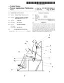
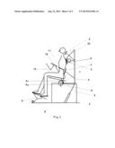
[0014] The subject under this Invention is exemplified in the drawings attached to this Application. They show one embodiment of the Invention. In FIG. 1, there is a diagrammatic drawing of a side-view of the furniture unit to sit-on, whereas in FIG. 2, there is a diagrammatic drawing of the furniture unit without its seat.
[0015] The furniture unit to sit-on has a main frame 2 connected by a joint with the frame base of the backrest 3. Above the main frame 2, a seat 1 is placed; it is fixed to the main frame 2 or, alternatively, to the frame base of the backrest 3 by a ball joint A. The said connection is made so that a bearing A1 of the ball joint A is mounted to the seat 1, and the ball A2 of the ball joint A is fixed onto the main base 2 or, alternatively, onto the frame base of the backrest 3. The frame base of the backrest 3 has armrests 11 mounted to an adjustable jib, as well as a working surface or a top 12 for a computer keyboard, mounted onto an another jig 13. An arm for securing a top for LCD monitor or PC screen is mounted to the jib 13 that fixes a working surface or a top 12 for keyboard.
[0016] The backrest frame 4 has a durable connection with the frame base of the backrest 3 and those two elements have jointly a possibility to adjust the up or down position and/or the inclination angle. The backrest frame 4 is equipped with three (3) independent movable rests: an upper headrest 5, a middle chestrest 6, and a lower backrest 7. The middle chestrest 6 is secured to the backrest frame 4 using a ball joint C whereas the upper rest 5 and the lower rest 7 are connected with the backrest frame 4 in a way that makes it possible to slightly (within a short distance range) move them forwards and backwards, or up and down, or aside. The rest elements 5 and 7 may be coupled with the backrest frame 4 using a spring-loaded telescopic mechanism. In the upper part of the backrest frame 4, a rest element 10 for lower extremities is placed on a jib.
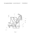
[0017] To the main frame 2, a footrest 8 is secured; it has two movable props for feet, which are connected by a flexible joint with the footrest frame using a crank assembly 9. The foot props can move up and down, as well as rotate. The footrest 8 is secured so that it can be freely pulled out and placed in a position allowing to place his/her feet thereon or it can be placed under the main frame 2 when not used. The footrest 8 can be situated using, for example, a rail, or it can have a telescopic connection. The latter makes it possible to adjust the distance between the footrest and the main frame 2.
User Contributions:
Comment about this patent or add new information about this topic:
| People who visited this patent also read: | |
| Patent application number | Title |
|---|---|
| 20130214416 | INTERCONNECT STRUCTURES AND METHODS OF MANUFACTURING OF INTERCONNECT STRUCTURES |
| 20130214415 | Metal Layer Air Gap Formation |
| 20130214414 | INTERCONNECT STRUCTURES AND METHODS OF MANUFACTURING OF INTERCONNECT STRUCTURES |
| 20130214413 | CONDUCTIVE LINE STRUCTURES AND METHODS OF FORMING THE SAME |
| 20130214412 | METHOD OF FORMING THIN FILM INTERCONNECT AND THIN FILM INTERCONNECT |
Images included with this patent application:
 |  |
 |
| Similar patent applications: | |
| Date | Title |
|---|---|
| 2013-10-10 | Furniture with integrated lap desk |
| 2008-12-25 | Three-piece knit form-fit slipcover |
| 2013-10-03 | Storage structure attached to car seat |
| New patent applications in this class: | |
| Date | Title |
|---|---|
| 2019-05-16 | Ez-ride car seat tray |
| 2016-12-29 | Chair and furniture set with the chair |
| 2016-06-30 | Assembly kit for generating an array of items of furniture |
| 2016-05-19 | Apparatus for support during tattooing |
| 2016-05-12 | Modular furniture |
| Top Inventors for class "Chairs and seats" | |
| Rank | Inventor's name |
|---|---|
| 1 | Johnathan Andrew Line |
| 2 | Larry P. Lapointe |
| 3 | Yukifumi Yamada |
| 4 | John W. Jaranson |
| 5 | Erwin Haller |