Patent application title: ENERGY CONVERTER
Inventors:
Gebhard Bernsau (Hohentengen, DE)
Manuel Bernsau (Birsfelden, CH)
IPC8 Class: AF01D2500FI
USPC Class:
415115
Class name: Rotary kinetic fluid motors or pumps with passage in blade, vane, shaft or rotary distributor communicating with working fluid
Publication date: 2013-07-18
Patent application number: 20130183139
Abstract:
1. The invention relates to an energy converter having a supply channel
for a medium and a turbine wheel (80) downstream from the supply channel.
A converter wheel (50) is connected downstream from the turbine wheel
(80) such that the inflowing medium can be accelerated by the converter
wheel (50), which is preferably caused to rotate by a drive motor (57) in
order to rotate the turbine wheel (80). The turbine wheel (80) drives a
generator (85) via a gearbox (82). The medium, which in in this case
flows in at an increased inlet flow velocity and which is, for example,
air, eventually causes the converter wheel (50) to rotate, and this
drives a further generator (117) via a further gearbox (116).Claims:
1. An energy converter having a supply channel for a medium and a turbine
wheel (80) downstream from the supply channel, characterized in that a
converter wheel (50) is connected downstream from the turbine wheel (80)
such that the converter wheel (50) caused to rotate by the medium in
order to rotate the turbine wheel (80) can be accelerated.
2. An energy converter according to claim 1, characterized in that the converter wheel (50) can be caused to rotate by a drive motor (57), wherein the medium flowing in at an increased inlet flow velocity eventually causes the converter wheel (50) to rotate.
3. An energy converter according to claim 1, characterized in that the supply channel is formed by a tubular part (100) fastened to an engine frame, wherein a moulded part (90) protruding into the end portion of the tubular part (100) is arranged on the side of the tubular part (100) facing the turbine wheel (80) and fastened to the engine frame (10) such that it directs the medium from the longitudinal axis of the tubular part (100) towards the inner wall of the tubular part (100).
4. An energy converter according to claim 3, characterized in that the moulded part (90) is formed conically and arranged concentrically to the tubular part (100).
5. An energy converter according to claim 3, characterized in that on its outer circumference, the moulded part (90) has guide vanes (91) each extending in the direction of the longitudinal axis of the tubular part (100) and being evenly spaced from each other on the outer circumference thereof such that a flow passage leading to the vanes (87) of the turbine wheel (80) is each formed between two adjacent guide vanes (91), a corresponding region of the outer circumference of the moulded part (90) and a corresponding region of the inner wall of the tubular part (100).
6. An energy converter according to claim 5, characterized in that the vanes (87) are evenly spaced from each other along a circumference of the turbine wheel (80), extend from the moulded part (90) to the side of the converter wheel (50) and are inclined in the circumferential direction of the turbine wheel (80).
7. An energy converter according to claim 5, characterized in that the number of the vanes (87) corresponds to the number of the guide vanes (91) or slightly differs therefrom.
8. An energy converter according to claim 3, characterized in that the turbine wheel (80) is connected to a turbine shaft (81) pivoted in the engine frame (10).
9. An energy converter according to claim 8, characterized in that the side of the turbine shaft (81) facing away from the turbine wheel (80) is connected to a generator (85) so as to rotate therewith.
10. An energy converter according to claim 9, characterized in that, a gearbox (82) is arranged between the side of the turbine shaft (81) facing the generator (85) and the generator (85).
11. An energy converter according to claim 10, characterized in that a coupling element (84) for connecting and disconnecting the generator (85) is arranged between the gearbox (82) and the generator (85).
12. An energy converter according to claim 1, characterized in that the converter wheel (50) is arranged on a hollow shaft (55) pivoted on the turbine shaft (81) so as to rotate therewith.
13. An energy converter according to claim 1, characterized in that the converter wheel (50) has outward-opening channels (48) arranged between two circular disks (51a, 51b) and running from its centre to the outside, wherein the medium is led to the outside upon rotation of the converter wheel (50).
14. An energy converter according to claim 13, characterized in that the channels (48) each comprise a first region (43) radially extending outwards from a centric pre-chamber (46) assigned to all channels (48) and an outward-opening second region (44) radially angled at the outside opposite to the first region approximately in the circumferential direction of the converter wheel (50).
15. An energy converter according to claim 14, characterized in that the channels (48) are each formed by means of baffles (44, 45) arranged between the circular disks (51a, 51b).
16. An energy converter according to claim 1, characterized in that on the side of the supply channel facing away from the turbine wheel (80), a funnel-shaped inlet channel part (103) is arranged, through which an additional medium flowing outside the energy converter (1) can be inserted into the supply channel.
17. An energy converter according to claim 16, characterized in that the longitudinal axis of the inlet channel part (103) is inclined towards the longitudinal axis of the supply channel at an angle of about 90.degree..
18. An energy converter according to claim 17, characterized in that the inlet channel part (103) is twistable about the longitudinal axis of the supply channel.
19. An energy converter according to claim 17, characterized in that the longitudinal axis of the inlet channel part (103) is arranged coaxially to the longitudinal axis of the supply channel.
20. An energy converter according to claim 1, characterized in that in the supply channel, on the side facing away from the turbine wheel (80), an atomizer unit (101) is arranged, through which a liquid or vaporous medium can be inserted into the supply channel.
21. An energy converter according to claim 1, characterized in that the medium contained in the supply channel is ambient air or water.
22. An energy converter according to claim 16, characterized in that the additional medium is air or formed by wind.
23. An energy converter according to claim 20, characterized in that the liquid or vaporous medium is water or formed by atomized water drops or atomized oil.
24. An energy converter according to claim 1, characterized in that it is surrounded by a shape (112) comprising a first shape region (113), which extends from the supply channel to the side of the converter wheel (50) and profiled such that the flow (106) is accelerated on the outer contour of the first shape region (113), wherein a low pressure is created on the upper surface of the first shape region (113) such that the accelerated flow (106) entrains the medium flowing out of the converter wheel (50), and thus accelerates the outflow (109) from the converter wheel (50), wherein a low pressure is caused in the converter wheel (50) and thus an increase of the inlet flow velocity (110) in the supply channel.
25. An energy converter according to claim 24, characterized in that the converter wheel (50) drives a further generator (116) via a further gearbox (117).
26. An energy converter according to claim 24, characterized in that the rotational speed of the converter wheel (50) is increased by a drive motor (57) in a differentiated manner depending on the flow velocity such that the inlet flow velocity is variable in order to circulate the turbine wheel (80) in an optimal way.
27. An energy converter according to claim 24, characterized in that the shape (112) comprises a second shape region adjoining the first shape region (113) and extending to the side facing away from the converter wheel (50) and covers the generator (116), the drive motor (57) as well as the gearbox (117).
28. An energy converter according to claim 24, characterized in that on the shape (112), a profile ring (115) surrounding the latter is provided such that on its inner surface, a circulating air flow (107) is created increasing the flow (106) on the outer contour of the first shape region (113) and thus its velocity.
29. An energy converter according to claim 24, characterized in that the shape (112) and/or, where applicable, the profile ring (115) are arranged concentrically to the longitudinal axis of the energy converter.
30. An energy converter according to claim 24, characterized in that a part of the energy generated is used for driving a pump (120a), which supplies water from a water supply (118) via a conduit (120b) to an elevated tank (119) in case there is an excess of electric power, and that water is supplied via the supply line (121b) and preferably an adjustable throttle (121a) to the atomizer (101) if current peaks are required in the power grid, wherein the supply pressure depends on the height of the water column (122) between the water surface in the tank (119) and the atomizer (101).
31. An energy converter according to claim 1, characterized in that it is mounted on the roof of a multi-story building.
Description:
[0001] The present invention relates to an energy converter according to
the preamble of patent claim 1.
[0002] DE 199 07 180 C2 discloses a floatable energy converter having a cylinder which is circulated by a liquid and in which a shaft with force transducer shapes is centrically arranged. The cylinder can be positioned in a river by means of floating bodies and an anchor being variable in height. Due to the flow inside the cylinder, the shaft is caused to rotate.
[0003] It is the object of the present invention to provide an energy converter which functions efficiently and which is capable of converting the energy of a fluid flowing inside a tubular part into energy with a relatively simple and compact design.
[0004] This technical problem is solved by an energy converter having a supply channel for a medium and a turbine wheel downstream from the supply channel, wherein a converter wheel is connected downstream from the turbine wheel such that the medium can be accelerated by the converter wheel caused to rotate in order to rotate the turbine wheel.
[0005] Due to the fact that the rotational speed of the converter wheel according to one embodiment of the invention is increased by a drive motor in a differentiated manner, the pressure difference between the pressure of the medium in the supply channel and the pressure in the region of the turbine wheel is increased. Advantageously, this leads to a substantially higher flow velocity of the medium in the supply channel, i.e. a substantially higher kinetic energy of the medium. Assuming that the power output of a conventional wind turbine is the same, the diameter of the turbine wheel of the energy converter according to the invention may advantageously be comparatively small. Compared with a conventional wind turbine, efficiency is furthermore substantially increased due to the large number of vanes of the turbine wheel in combination with the corresponding number of guide vanes of the guide vane ring of the moulded part. The design of the present energy converter may be relatively small with the Power output of a wind turbine and the present energy converter being the same. Advantageously, a switching off of the present energy converter is not necessary in case of high flow velocities. In contrast, conventional wind turbines have to be switched off at high wind velocities. By encasing the present energy converter, detrimental effects on the environment, e.g. noise or shadow flicker at low positions of the sun, can be avoided. Injury to birds to be feared in case of wind turbines can be excluded in the operation of the present energy converter.
[0006] Advantageously, the present energy converter can be produced, transported and mounted at relatively low cost due to its compactness and small size. Since all components of the present energy converter can be arranged at ground level, the structural design may be relatively simple. Preferably, the present energy converter is relatively insensitive to lightning strike. In the event of sudden wind gusts, there is no risk of damage.
[0007] By means of the generator driven by the turbine wheel of the present energy converter, a constant power generation can be achieved by adjusting the rotational speed of the converter wheel in such a way that a constant volume flow rate of the medium is set in the supply channel. The medium, which in this case flows in at an increased inlet flow velocity and which is, for example, air, eventually causes the converter wheel to rotate and drives a further generator via a further gearbox. Depending on the flow velocity, a differentiated increase of the rotational speed is transferred to the converter wheel by the drive motor when required in order to modify the inlet flow velocity such that the turbine wheel is circulated in an optimal way. Thus, it is not necessary to change the angle of attack of the vanes and the guide vanes.
[0008] In a preferred embodiment of the energy converter according to the invention, the supply channel is formed by means of a tubular part fastened to an engine frame, wherein a moulded part protruding into the end portion of the tubular part is arranged on the side of the tubular part facing the turbine wheel and fastened to the engine frame. The moulded part is formed in such a way that it directs the medium from the longitudinal axis of the tubular part towards the inner wall of the tubular part. Expediently, the moulded part is formed conically and arranged concentrically to the tubular part. On its outer circumference, the moulded part of a preferred embodiment of the energy converter according to the invention has guide vanes each extending in the direction of the longitudinal axis of the tubular part and being evenly spaced from each other on the outer circumference thereof. In this way, a flow passage leading to the vanes of the turbine wheel is each formed between two adjacent guide vanes, a corresponding region of the outer circumference of the moulded part and a corresponding region of the inner wall of the tubular part.
[0009] In a preferred energy converter, the vanes of the turbine wheel are evenly spaced from each other along a circumference of the turbine wheel. They extend from the moulded part to the side of the converter wheel and are inclined in the circumferential direction of the turbine wheel. The number of the vanes may correspond to the number of the guide vanes or slightly differ therefrom in order to avoid noise.
[0010] Preferably, the turbine wheel is connected to a turbine shaft pivoted in the engine frame. For power generation, the side of the turbine shaft facing away from the turbine wheel may be connected to a generator so as to rotate therewith. Between the side of the turbine shaft facing the generator and the generator, a gearbox can be arranged, the transmission ratio of which may expediently be variable. In order to enable a disconnection of the generator from the turbine wheel, a coupling element for connecting and disconnecting the generator may be arranged between the gearbox and the generator.
[0011] In a preferred embodiment of the invention, the converter wheel is arranged on a hollow shaft pivoted on the turbine shaft so as to rotate therewith. Between two congruently arranged circular disks being spaced from each other, the converter wheel preferably has outward-opening channels running from its centre to the outside, in which the medium is led out upon rotation of the converter wheel. Preferably, the channels each comprise a first region radially extending outwards from a centric pre-chamber assigned to all channels and an outward-opening second region radially angled at the outside opposite to the first region approximately in the circumferential direction of the converter wheel. Expediently, the channels are each formed in a particularly simple manner by means of baffles arranged between the circular disks.
[0012] In a preferred further development of the energy converter according to the invention, on the side of the supply channel facing away from the turbine wheel, a funnel-shaped inlet channel part is arranged, through which an additional medium flowing outside the energy converter can be inserted into the supply channel. The longitudinal axis of the inlet channel part may be inclined towards the longitudinal axis of the supply channel, preferably at right angles. In a preferred application, the additional medium can be wind captured by the inlet channel part. The inlet channel part may be twistable about the longitudinal axis of the supply channel.
[0013] Particularly preferably, air serves as a medium. In a further preferred embodiment of the invention, an atomizer unit is arranged in the supply channel, preferably on the side facing away from the turbine wheel, through which a liquid or vaporous medium, preferably water, atomized water drops or atomized oil, can be inserted into the supply channel.
[0014] The invention and its embodiments will be described in more detail below with reference to the figures.
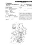
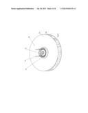
[0015] FIG. 1 shows a perspective view of a preferred embodiment of the energy converter according to the invention;
[0016] FIG. 2 shows a cross-section through the energy converter of FIG. 1 along the line II-II;
[0017] FIG. 3 shows an alternative embodiment of a turbine wheel;
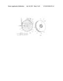
[0018] FIGS. 4a and 4b show illustrations explaining the design and functioning of the converter wheel;
[0019] FIG. 5 shows a perspective view of the converter wheel with a turbine wheel;
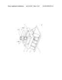
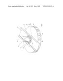
[0020] FIG. 6 shows a perspective view of the converter wheel, the turbine wheel as well as the guide vane ring connected upstream;
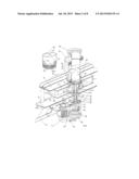
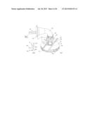
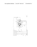
[0021] FIG. 7 shows the converter wheel, the turbine wheel, the guide vane ring connected upstream, the inlet channel, a rotating assembly as well as an atomizer unit and an inlet channel part; and
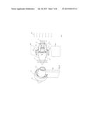
[0022] FIGS. 8 to 11 show further developments of the invention.
[0023] According to FIG. 1, a preferred embodiment of the energy converter 1 according to the invention comprises an engine frame 10, at which a converter wheel 50 and a turbine wheel identified by reference numeral 80 are pivoted. That is to say the turbine wheel 80 is connected to a turbine shaft 81 so as to rotate therewith, with the latter being pivoted in a bearing flange 56 installed in the engine frame 10. On the side of the turbine shaft 81 facing the turbine wheel 80, a generator 85 is mounted on the turbine shaft 81 so as to rotate therewith, with the generator 85 producing electric energy upon rotation of the turbine shaft 81. The generator 85 is attached to console parts 83 and 86, which are connected to the engine frame 10.
[0024] Furthermore, a drive motor 57 is connected to the engine frame 10, the output drive 58 of which supports a first pulley 51. Via a belt part 59, the first pulley 51 is connected to a second pulley 60, which is connected to a hollow shaft 55 so as to rotate therewith. In this way, the rotation of the drive motor 57 is transferred to the converter wheel 50 via the first pulley 51, the belt part 59, the second pulley 60 and the hollow shaft 55. The hollow shaft 55 is mounted on the engine frame 10 by means of a bearing flange 56.
[0025] The bearing flange 56 comprises a first bearing part 53 for supporting the hollow shaft 55. A second bearing part 52 for supporting the hollow shaft 55 is axially spaced from the first bearing part 53, with the second bearing part 52 being supported in an axially extending extension 49, which is preferably formed as a single piece together with the bearing flange 56.
[0026] It is pointed out that the transfer of the rotation of the drive motor 57 to the converter wheel 50 can also be carried out in another way.
[0027] A tubular part 100 serving as a supply channel is connected to the engine frame 10. The end of the tubular part 100 facing the engine frame 10 is preferably retained in a supporting ring 92 mounted on the engine frame 10.
[0028] In the end portion of the tubular part 100 facing the engine frame 10, a moulded part 90 is located, which is attached to the supporting ring 92 so as to rotate therewith and the shape of which conically extends towards the engine frame 10, wherein guide vanes 91, which are preferably evenly spaced from each other and which radially extend outwards from the moulded part 90 to the inner wall of the tubular part 100, are attached to the lower end portion of the conical moulded part 90 and/or the end portion of the conical moulded part 90 facing the engine frame 10. The guide vanes 91 form a guide vane ring. The lower regions 94 of the guide vanes 91 facing away from the moulded part 91 are preferably angled to the upper axially extending regions 95 of the guide vanes 91 in the circumferential direction of the moulded part 90, as can clearly be seen from FIG. 3.
[0029] Below the tubular part 100 and the guide vane ring 93, the turbine wheel 80 is located, which is connected to the turbine shaft 81 so as to rotate therewith.
[0030] The vanes 87 of the turbine wheel 80 extend from the moulded part 90 to the side of the generator 82 and are inclined in the circumferential direction of the turbine wheel 80 opposed to the regions 94 of the guide vanes 91. In this way, a particularly effective rotation of the turbine wheel 80 is achieved.
[0031] Below the hollow shaft 55 of the turbine wheel 80, the converter wheel 50 is arranged and connected to the hollow shaft 55 so as to rotate therewith.
[0032] According to FIG. 4b, the converter wheel 50 comprises channels 48, which are evenly spaced from each other in the circumferential direction between two circular disks 51a and 51b, each radially extending outwards from the centre 47 of the converter wheel 50 and running against the rotational direction of the converter wheel 50 at an angle of preferably 90° just before the outer diameter of the converter wheel 50. The channels 52 run radially inwards into a common angular pre-chamber 46 surrounding the annular centre member 54 of the converter wheel 50. Expediently, the centre member 54 extends with its region 54a facing the disk part 51a in an arch-shaped manner outwards from the longitudinal axis of the converter wheel 50. A particularly good and irrotational flow of the medium from the pre-chamber 56 into the channels 48 can thus be ensured. Above the arch-shaped region 54a, the centre member 54 may extend with its region 54b concentrically to the longitudinal axis of the converter wheel 50 and the annular channel 41 of the disk part 51a spaced therefrom. It is also possible that the annular channel 41 of the disk part 51a according to FIG. 8 has a necking 41a directed to the longitudinal axis of the converter wheel 50 in order to achieve a higher flow velocity of the fluid in the pre-chamber 46.
[0033] The individual channels 48 are formed by means of baffles 44 and 45, which each extend outwards from the annular pre-chamber 46 in a straight line as shown in FIG. 4a and which, for the formation of the channels 48, are angled in such a way that in the straight-lined region, the region 43 of the channel 48 approximately radially extending outwards is formed between two adjacent baffles 44 and 45, and the region 42 preferably extending at right angles to the region 43 radially extending outwards is formed between the angled end portions of the baffles 44 and 45.
[0034] Upon rotation of the converter wheel 50 by the drive motor 57 in the rotational direction shown in FIG. 4a, a medium located in the channels 48 is subjected to a centrifugal force Fz1 by the rotatory motion with a rotational speed n. This centrifugal force Fz1 is determined by the circumferential velocity v1 at radius r1 and the mass m of the medium. The formula for calculating centrifugal the force is:
Fz 1 = m v 1 2 r 1 ##EQU00001##
[0035] The formula for calculating the circumferential velocity is:
v1=2r1πn
[0036] The centrifugal force Fz1 presses the medium in the channels 48 to the outside. At radius r2 just before the right-angled bend of the channels 48, the following holds with respect to the centrifugal force:
Fz 2 = m v 2 2 r 2 ##EQU00002##
[0037] The centrifugal force Fz2 accelerates the mass m of the medium to a velocity v3, with the frictional loss being taken into account. At this place, i.e. just before the bend of the channels 48, the kinetic energy of the mass m of the medium is:
WK 3 = m v 3 2 2 ##EQU00003##
[0038] Due to the bend of the channels 48, the medium is redirected against the rotational direction. After the bend, it is subjected to a velocity v4, which is lower than the velocity v3 because of the frictional losses. This results in the kinetic energy:
WK 4 = m v 4 2 2 ##EQU00004##
[0039] The medium exits the converter wheel 50 with a kinetic energy W4, which causes a reaction thrust with the same energy. This energy helps to drive the converter wheel 50.
[0040] During the process described above, a low pressure is created in the pre-chamber 46, having the effect that the external atmospheric pressure 62 has in turn the effect that the medium is accelerated before the converter wheel 50 and supplied through the annular channel identified by reference numeral 41 (FIG. 4b) to the converter wheel 50. The difference in pressure ΔP can be increased by increasing the rotational speed of the converter wheel 50 driven by the drive motor 57.
[0041] In the event that the converter wheel 50 is caused to rotate by the drive motor 57, the medium in the channels 43 of the converter wheel 50 is pressed to the outside as described with reference to FIG. 4a, which is why a low pressure is created in the region below the turbine wheel 80, which is pivoted in the annular channel 41. As a result, the medium flows from the tubular part 100 through the channels formed between the guide vanes 91 towards the vanes 87 due to said pressure and the atmospheric pressure 62 prevailing in the tubular part 100. At the same time, the turbine wheel 80 is caused to rotate and transfers its rotation via the turbine shaft 81 to the generator 85, which produces electric energy corresponding to the rotation. Said volume flow 40 can clearly be seen from FIG. 6.
[0042] According to FIG. 3, the guide vanes 91 are preferably bent in such a way that they face downwards in the rotational direction of the turbine wheel 80. As already mentioned above, the moulded part 90 and the guide vanes 91 are retained on the engine frame 10 by the supporting ring 92.
[0043] The volume flow 40 is redirected by the moulded part 90 in such a way that optimal pressure is applied to the vanes 87 of the turbine wheel 80. Via the moulded part 90, the volume flow 40 is directed to the annular ring 41 between the moulded part 90 and the supporting ring 92. As a result, the velocity of the medium is still increased, which also leads to a further increase of pressure on the turbine wheel 80.
[0044] According to FIG. 7, it is possible to provide a funnel shaped inlet channel part 103, the longitudinal axis of which extends, for example, perpendicular to the longitudinal axis of the tubular part 100 and which is pivoted in a rotating assembly 102, which is connected to the upper end of the tubular part 100. It is possible in this way to twist the funnel-shaped inlet channel part 103 around the longitudinal axis of the tubular part 100 so that it is, for example, pivotable in the wind direction identified by reference numeral 105. For example, the air flow of a ship can be captured if the energy converter 1 according to the invention is arranged on a ship. The difference in pressure ΔP thus caused by the converter wheel 50 is then increased by the dynamic pressure generated by the wind 105. This pressure accelerates the mass m of the medium to a velocity v5. This leads to a kinetic energy acting on the turbine wheel 80:
WKTurbine = m v 5 2 2 ##EQU00005##
[0045] For further increasing the kinetic energy, an atomizer unit 101 may be provided in the tubular part 100, through which a liquid, e.g. water or a vaporous medium, can be supplied to the medium located in the tubular part 100, with the medium preferably being the ambient air. This additional medium is entrained by said volume flow 40 and also accelerated to the velocity v5. In this connection, the length 6 of the tubular part 100, i.e. the distance between the atomizer unit 101 and the turbine wheel 50, plays a decisive role.
[0046] The kinetic energy of the turbine wheel 80 is transferred to the turbine shaft 81 with high efficiency (FIG. 2). For example, the high rotational speed of the turbine shaft 81 is reduced via a gearbox 82, with the corresponding torque being increased. According to FIG. 2, the gearbox 82 is preferably connected to said console part 83. In FIG. 2, a coupling element is identified by reference numeral 84, by means of which the gearbox 82 can be connected to the inlet of the generator 85.
[0047] It is pointed out that, depending on the requirement, the present energy converter 1 can be mounted in various positions. Preferably, the longitudinal axis of the energy converter 1 may be aligned vertically or horizontally. The shape and the number of channels 48 of the converter wheel 50, the axial dimension of the converter wheel 50 as well as the dimensions of the tubular part 100 can be determined and optimized as regards the efficiency of the energy converter 1.
[0048] A further embodiment of the energy converter according to the invention is described with reference to FIGS. 9 to 11. This embodiment is particularly well suited for the mounting on roofs of multi-storey buildings or the like. Details of FIGS. 9 to 11 already described with reference to FIGS. 1 to 8 are identified accordingly. As is apparent, the energy converter is preferably mounted on a mast 123 or the like.
[0049] An inner shape 112 surrounding the tubular part 100 with a shape region 113 is attached to the outward-opening tubular part 100 (FIG. 9). The shape region 113 extends in the direction of the converter wheel 50. In addition, the shape 112 comprises a further shape region 114 leading from the converter wheel 50 to the side facing away from the shape region 113 and serving simultaneously as a cover of the generator and the drive chamber.
[0050] The shape 112 is arranged coaxially to the longitudinal axis preferably extending horizontally and/or to the centre 47.
[0051] Preferably, the shape 112 is a round moulded part being profiled in such a way that the flow 106 is accelerated on the contour of the shape, with a low pressure being created on the upper surface of the shape 112 as in case of an aerofoil of an aeroplane.
[0052] An outer profile ring 115 centrically attached to the shape 112 is subjected to a circulating flow 108 on its outer surface and a circulating flow 107 on its inner surface. The circulating flow 107 increases the flow 106 and thus its velocity. The circulating flows 106, 107, 108 all run in the direction of the wind flow 111 "streaming out". The wind direction of the wind flow streaming in is identified by reference numeral 105.
[0053] The flow 106 with the accelerated velocity entrains the air flowing out of the converter wheel 50 and thus accelerates the outflow 109 at the converter wheel 50. This, in turn, causes a low pressure in the converter wheel 50 and thus a further increase of the difference in pressure ΔP after the turbine wheel 80. As a result, the inlet flow velocity 110 is increased at the tubular part 100.
[0054] As already described above, the outflow 109 at the converter wheel 50 causes a reaction thrust at the converter wheel 50 and causes the converter wheel 50 to rotate. This energy can, for example, be supplied to an additional generator 116 via a gearbox 117 (FIG. 11) and converted into electric energy.
[0055] By means of the drive motor 57, a specific rotational speed is produced at the converter wheel 50 preferably in a differentiated manner. This differentiated rotational speed affects the inflow 110 before the turbine wheel 80 and serves the purpose to operate the turbine within the optimal range at various fluid velocities, e.g. wind velocities. This means that an adjustment of the guide vanes as well as an adjustment of the turbine vane is not necessary. The energy of the turbine wheel 80 is supplied to the generator 85 via the gearbox 82 as already described above.
[0056] According to FIG. 11, a part of the energy generated (e.g. electric energy) can be used for driving a pump 120a, which supplies water from a water supply 118, for example a lake or a sea, via a conduit 120b to an elevated tank 119. This supply always takes place every time there is a so-called excess of, for example, electric power. If current peaks are suddenly required in the power grid, water is supplied via the supply line 121b and an adjustable throttle 121a to the atomizer 101, which is shown schematically. The supply pressure depends on the height of the water column 122. The additionally injected, atomized water is entrained by the wind and thus the inflowing mass increased. As a result, the energy generated is increased as already described above.
[0057] The advantage of the embodiment of the energy converter according to the invention described with reference to FIGS. 9 to 11 is that it can additionally be used as a so-called pumped-storage hydropower plant. The necessary additional power does not have to be generated by the plant operators exclusively.
REFERENCE NUMERALS
[0058] 1 energy converter
[0059] 6 length
[0060] 10 engine frame
[0061] 40 volume flow
[0062] 41 annular ring
[0063] 41a necking
[0064] 42 region
[0065] 43 region
[0066] 44 baffle
[0067] 45 baffle
[0068] 46 pre-chamber
[0069] 47 centre
[0070] 48 channel
[0071] 49 extension
[0072] 50 converter wheel
[0073] 51 pulley
[0074] 51a circular disk
[0075] 51b circular disk
[0076] 52 bearing part
[0077] 53 bearing part
[0078] 54 centre member
[0079] 54a region
[0080] 54b region
[0081] 55 hollow shaft
[0082] 56 bearing flange
[0083] 57 drive motor
[0084] 58 output drive
[0085] 59 belt part
[0086] 60 pulley
[0087] 63 external pressure
[0088] 80 turbine wheel
[0089] 81 turbine shaft
[0090] 82 gearbox
[0091] 83 console part
[0092] 84 coupling element
[0093] 85 generator
[0094] 86 console part
[0095] 87 vane
[0096] 90 moulded part
[0097] 91 guide vane
[0098] 92 supporting ring
[0099] 93 guide vane ring
[0100] 94 region
[0101] 95 region
[0102] 100 tubular part
[0103] 101 atomizer unit
[0104] 102 rotating assembly
[0105] 103 inlet channel part
[0106] 104 channel part
[0107] 105 wind direction
[0108] 106 flow
[0109] 107 flow
[0110] 108 flow
[0111] 109 outflow
[0112] 110 inflow
[0113] 111 wind flow
[0114] 112 shape
[0115] 113 shape
[0116] 114 shape
[0117] 115 profile ring
[0118] 116 generator
[0119] 117 gearbox
[0120] 118 water supply
[0121] 119 tank
[0122] 120a pump
[0123] 120b conduit
[0124] 121a throttle
[0125] 121b supply line
[0126] 122 height
[0127] 123 mast
User Contributions:
Comment about this patent or add new information about this topic:
Images included with this patent application:
 |  |
 |  |
 |  |
 |  |
 |
| Similar patent applications: | |
| Date | Title |
|---|---|
| 2010-08-26 | Fluid flow energy concentrator |
| 2013-10-24 | Energy conversion device |
| New patent applications in this class: | |
| Date | Title |
|---|---|
| 2022-05-05 | Fabricated cmc nozzle assemblies for gas turbine engines |
| 2019-05-16 | Ogv electroformed heat exchangers |
| 2018-01-25 | Intermediate case for an aircraft turbomachine made from a single casting with a lubricant duct |
| 2018-01-25 | Turbine vane with coupon having corrugated surface(s) |
| 2018-01-25 | Blade with internal rib having corrugated surface(s) |
| Top Inventors for class "Rotary kinetic fluid motors or pumps" | |
| Rank | Inventor's name |
|---|---|
| 1 | Gabriel L. Suciu |
| 2 | Frederick M. Schwarz |
| 3 | United Technologies Corporation |
| 4 | Brian D. Merry |
| 5 | Craig M. Beers |