Patent application title: MONOLITH WITH CATALYTIC OR SORBENT BEADS
Inventors:
William A. Whittenberger (Leavittsburg, OH, US)
William A. Whittenberger (Leavittsburg, OH, US)
Lorne W. Deyoung (Southington, OH, US)
Todd A. Romesberg (Vienna, OH, US)
David A. Becker (Hiram, OH, US)
Snezana Aleksic (Pittsburgh, PA, US)
Assignees:
CATACEL CORP.
IPC8 Class: AB01J3500FI
USPC Class:
428 68
Class name: Stock material or miscellaneous articles sheet including cover or casing
Publication date: 2013-07-04
Patent application number: 20130171404
Abstract:
A monolith for catalytic or sorbent purposes. The monolith includes a
substrate sheet having attached thereto a plurality of catalytic or
sorbent beads. Each bead has a diameter of at least fifty microns. The
substrate sheet at least partially defines one or more channels through
the monolith. Fluid flowing through the channels will contact the beads
for catalytic or sorbent purposes.Claims:
1. A monolith for catalytic or sorbent purposes, the monolith comprising
a substrate sheet having attached thereto a plurality of catalytic or
sorbent beads, each bead having a diameter of at least 50 microns, each
bead having catalytic or sorbent material on an exposed surface of the
bead, the substrate sheet at least partially defining one or more
channels through the monolith, the one or more channels being effective
to permit a fluid to contact the beads when the fluid flows through the
channel.
2. The monolith of claim 1, wherein each bead has a diameter of 50 microns to 10 mm.
3. The monolith of claim 1, wherein the beads are attached to the substrate sheet by an organic adhesive.
4. The monolith of claim 1, wherein the beads are catalytic beads effective to catalyze one or more reactions selected from the group consisting of reforming of methanol, conversion of CO to CO2, water-gas shift, oxidation of methanol to formaldehyde, converting ozone to oxygen, oxidation of a hydrocarbon, and reduction of NON.
5. The monolith of claim 1, wherein the beads are sorbent beads effective to (a) sorb CO2 or SON or NO from a gas, (b) sorb CO2 or sulfur compounds or heavy hydrocarbons from natural gas, (c) separate CO2 or hydrogen or another gas from syngas, or (d) separate H2O from a gas.
6. The monolith of claim 1, wherein the beads can perform their catalytic or sorbent function effectively at a process temperature between 4.degree. C. and 300.degree. C.
7. The monolith of claim 1, wherein the substrate sheet is spirally wound.
8. The monolith of claim 1, the substrate sheet having a top surface and a bottom surface, to each surface there being attached a plurality of said beads.
9. The monolith of claim 1, comprising a plurality of said substrate sheet, each substrate sheet being substantially planar, the substrate sheets being arranged one adjacent the next in a stack.
10. The monolith of claim 9, further comprising a separator sheet between adjacent substrate sheets.
11. The monolith of claim 1, further comprising a separator sheet, the separator sheet at least partially defining the one or more channels.
12. The monolith of claim 1, further comprising a tube, the monolith being disposed within the tube.
13. A method of making a monolith for catalytic or sorbent purposes, comprising the steps of: (a) providing a substrate sheet having a top surface and a bottom surface; (b) coating one or both of the surfaces with an adhesive composition; and (c) contacting the coated surface or surfaces with a plurality of catalytic or sorbent beads so that the beads are attached to the substrate sheet, each bead having a diameter of at least 50 microns, each bead having catalytic or sorbent material on an exposed surface of the bead.
Description:
FIELD OF THE INVENTION
[0001] The invention relates to monoliths having attached thereto catalytic beads or sorbent beads, for catalytic or sorbent purposes.
BACKGROUND OF THE INVENTION
[0002] Ceramic bead catalysts in a packed bed have been used for many years for a variety of reactions, including steam reforming of methane, reforming of methanol, conversion of CO to CO2, water-gas shift, or oxidation of methanol to form formaldehyde, and oxidation of ethylene to form ethylene oxide. Packed bed catalyst designs are also used in some pollution control applications. Packed bed catalyst designs have always been negatively affected by pumping losses caused by pressure drop as the liquid or gas fluid flows through the packed bed.
[0003] Some of these packed bed reactions (for example, steam reforming of methane) mitigate the pressure drop problem by using large beads in the packed bed, ie, 10 mm or more. Less surface area, and sometimes less heat transfer is available with larger beads, but these reduced properties are acceptable in some cases. Other packed bed reactions cannot operate effectively without the properties of the smaller beads, with characteristic size of 6 mm or less.
[0004] It is also known to use beds packed with sorbent beads. Such packed beds will absorb or adsorb a particular species of gas or liquid from a mixture that is passed through the bed. Such beds also sometimes require small beads to operate effectively.
[0005] All such packed beds can be characterized as random or loose packed, with associated un-ordered or turbulent flow of gas or liquid through the bed. One problem with loose or random packed beds is that, when the metal container or enclosure surrounding the ceramic beads or media cools and contracts, the ceramic beads or media may be compacted, crushed, cracked or flaked, causing degradation of the beads or media, and the resulting powder/flakes tends to clog the bed.
[0006] Catalytic monoliths for reaction purposes are also known wherein a metallic foil is coated on both sides with an appropriate catalyst; one or more pieces of coated foil are then secured together to form the monolith; see, eg: U.S. Pat. Nos. 7,320,778 and 7,077,999. However, coating the foil with catalyst is an expensive and difficult task. There is a need for a simpler, less expensive, more effective way to achieve catalytic reactions and sorbent separations using catalytic or sorbent beads.
SUMMARY OF THE INVENTION
[0007] A monolith for catalytic or sorbent purposes is provided. The monolith comprises a substrate sheet having attached thereto a plurality of catalytic or sorbent beads, each bead having a diameter of at least fifty microns. Each bead has catalytic or sorbent material on an exposed surface of the bead. The substrate sheet at least partially defines one or more channels through the monolith. The channels are effective to permit a fluid to contact the beads when the fluid flows through the channel.
BRIEF DESCRIPTION OF THE DRAWINGS
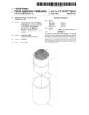
[0008] FIG. 1 shows a monolith 3 according to the invention and a tube or enclosure 2 into which the monolith can be inserted.
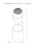
[0009] FIG. 2 shows a view of a top surface of a substrate sheet 5 with catalytic or sorbent beads 6 attached thereto.
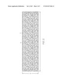
[0010] FIG. 3 shows a side view of a substrate sheet with catalytic or sorbent beads attached to the top and bottom surfaces, and an adjacent separator sheet prior to the formation of the monolith.
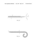
[0011] FIG. 4 shows a side view of an arrangement similar to FIG. 3, wherein the substrate sheet and separator sheet are beginning to be rolled to form a monolith.
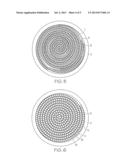
[0012] FIG. 5 shows a monolith 3 according to the invention inside a reactor body or tube.
[0013] FIG. 6 shows an alternative embodiment of a monolith according to the invention inside a reactor body or tube.
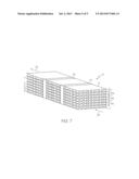
[0014] FIG. 7 shows an alternative embodiment of a monolith according to the invention wherein flat substrate sheets are stacked together.
DETAILED DESCRIPTION OF PREFERRED EMBODIMENTS OF THE INVENTION
[0015] When a range, such as 5-25, is given, this means preferably at least 5 and, separately and independently, preferably not more than 25.
[0016] FIG. 1 shows schematically a reactor or enclosed monolith 1 comprising a monolith 3 to be positioned inside a reactor body or tube or enclosure 2 having an opening or inlet 4a and a corresponding opening or outlet 4b. Tube 2 can be much longer; tube 2 can hold a single monolith 3 or a plurality of monoliths 3 stacked one atop the other inside the tube 2.
[0017] As known in the art, the monolith 3 will be placed or slid into or located within the tube 2 so that fluid (such as gas or liquid) to be reacted or sorbed will enter the monolith 3 at end 17a, flow through the channels 11 through the monolith and exit the monolith at end 17b.
[0018] The tube 2 is generally as known in the art. It is preferably made of metal, such as steel, stainless steel, aluminum or Inconel; alternatively (and preferably if the reaction is a low temperature reaction like CO to CO2) made of polymeric or plastic material. It is preferably a tube having a circular, rectangular, oval, or other cross-section. Its diameter (or length of side, if rectangular) is preferably at least 5, 8, 10, 15, 20 or 25 cm; its diameter (or length of side, if rectangular) is preferably not more than 90, 70, 60, 50, 40, 30, 25, 20, 15, or 12 cm. Alternatively, the tube 2 can have a rectangular cross section of not more than 3, 6, 8, 10, 15 or 20 m on each side or can have a circular cross section with a diameter of not more than 3, 6, 8, 10, 15 or 20 m. The length of the tube 2 is preferably at least 2, 4, 6, 10, 20, 40, 80, 150 or 300 cm and preferably not more than 600, 500, 400, 300, 200, 100 or 50 cm.
[0019] FIG. 1 shows a monolith 3 comprising a substrate sheet 5 having attached thereto a plurality of catalytic or sorbent beads 6. Substrate sheet 5 and separator sheet 7 (described later) can be spirally wound together to form the monolith 3 and are held together by a surrounding band (or wire) 10, preferably thin and flat and metal or plastic or polymeric. Alternatively, the spiral can be held together by welding, clips, or other fasteners or fastening means known in the art. The spiral winding defines one or more channels 11 (between the sheets 5 and 7) so that fluid can flow in one end 17a of the monolith, through the channel(s) 11, and out the other end 17b of the monolith.
[0020] FIG. 7 shows an alternative embodiment of a monolith according to the invention wherein separate flat layers are stacked on top of each other. Monolith 12 comprises a substrate sheet 14 to the bottom surface of which are attached a plurality of catalytic or sorbent beads 6. As shown, beads 6 are also attached to the top and bottom surfaces of flat substrate sheets 14a, 14b and 14c. Sheets 14, 14a, 14b and 14c are the same as substrate sheet 5. Several flat or corrugated separator sheets 7 are interleaved to help define channels or flow channels 11 between sheets 7 and 5. Of course, the beads 6 are located in the flow channels. Metallic or plastic bands 16, 18 hold the sheets together to form the monolith. Alternatively, the loose stack can be held together by other means, such as a surrounding enclosure with 2 open ends. When the rectangular monolith 12 is slid into the rectangular cross section tube 2, the liquid or gas fluid can flow through the monolith such as by flowing through the channels 11 in the direction from arrow 20 to arrow 22.
[0021] As known in the art, the monolith 3, 12 preferably has outside lateral dimensions so that it will fill the cross-sectional area of the reactor body or tube or enclosure 2. The monolith preferably has a circular, rectangular or oval cross-section. Its cross-sectional diameter (if circular) or length of side (if rectangular) is preferably at least 5, 8, 10, 15, 20 or 25 cm and preferably not more than 240, 120, 90, 70, 60, 50, 40, 30, 25, 20, 15 or 12 cm. For example, a rectangular monolith as shown in FIG. 7 can be made with cross-section of 30 cm by 120 cm or 60 cm by 60 cm, to form "bricks". The bricks can then be stacked up, for example, in a grid structure having vertical, horizontal, and/or diagonal support members, to hold the bricks in a large air stream tube having, for example, a 10 m×10 m cross section. The monolith (and accordingly, the flow channel 11) preferably has a length of at least 2, 4, 6, 8, 10, 14, 18, 20, 25 or 30 cm and preferably not more than 60, 50, 40, 30, 25, 20, 18, 14 or 10 cm. Typically, 1, 2, 3, 4, 5, 6, 7, 8, 9 or 10 or more monoliths will be stacked in a row, one after the other, inside the tube 2, with all the flow channels 11 aligned so that a single portion of fluid can flow through all the monoliths in the tube 2.
[0022] As shown in FIGS. 2 and 3, catalytic or sorbent beads 6 are attached to the top surface 8 and/or bottom surface 9 of substrate sheet 5. As shown in FIG. 3, beads are preferably not attached to a terminal portion of the top and bottom surfaces of sheet 5 so that, when the spiral is made, there is less of a gap between the outside of the monolith 3 and the inside of the tube 2 (see FIGS. 5 and 6).
[0023] Substrate sheet 5 is preferably a thin sheet or foil, such as 0.001-0.010 inches thick, of metal, preferably steel, stainless steel, aluminum, Inconel, or Fecralloy, or plastic or polymer (polyester, polyethylene, polyvinylchloride, etc.) or paper, stiff paper, thick paper or thin cardboard. Alternatively, sheet 5 can be double sided or single sided adhesive tape, or single sided or double sided aluminum adhesive tape. The length of sheet 5 is long enough to provide the desired cross-sectional diameter or side; the width of sheet 5 is sufficient to provide the desired length of flow channel 11.
[0024] Beads 6 can be catalytic beads to catalyze reactions, such as reforming of methanol, conversion of CO to CO2, water-gas shift, oxidation of methanol to formaldehyde, converting ozone to oxygen, oxidation of hydrocarbons, oxidation reactions for emission control, and reduction of NOR.
[0025] Beads 6 can be sorbent beads to absorb or adsorb a particular species of gas or liquid from a mixture, for example sorbing CO2 or SOx or NO from a gas or exhaust gas, separating CO2 or sulfur compounds or heavy hydrocarbons from natural gas, separating CO2 or hydrogen or other gases from syngas, or separating steam and water from a gas stream.
[0026] Preferred catalytic or sorbent beads to perform these functions are known in the art and are available from catalytic and sorbent bead manufacturers and distributors, such as: Sud-Chemie AG, headquartered in Munich, Germany (www.sud-chemie.com), BASF Corporation, Florham Park, N.J. and BASF SE, Ludwigshafen, Germany (www.basf.com); Johnson Matthey PLC, London, England (www.matthey.com); UOP LLC, Des Plaines, Ill. (www.uop.com); W.R. Grace & Co., Chicago, Ill. (www.qrace.com); and Molecular Products Limited, Essex, United Kingdom (www.molecularproducts.com). The catalytic and sorbent beads supplied by these entities can be used in the invention and are hereby incorporated herein by reference. Zeolite beads can be used. Catalytic and sorbent material is known in the art and can include nickel, palladium, platinum, zirconium, rhodium, ruthenium, iridium, cobalt and aluminum oxide.
[0027] Beads 6 are preferably spherical or spheroidal or substantially spheroidal or roughly or somewhat spheroidal or roundish or misshapen spheroids or elliptical, oval or nonuniform or shaped bodies like pellets, granules, gravel, pebbles or stones, such as pebbles found on beaches or in stream-beds. Beads 6 are preferably shaped like the catalytic and sorbent beads available from the manufacturers listed above. Beads 6 can also be cylindrical or other shapes.
[0028] As used herein and in the claims, the diameter of a bead is the average of 20 diameters taken or measured at 20 different equally spaced (from an angular perspective) points or locations around the bead. Beads 6 have a diameter of preferably at least 50, 100, 200, 300, 400, 500, 600, 800, 1000, 1500, 2000, 3000, 4000, 5000, 6000, 7000, 8000, or 9000 microns and preferably not more than 10000, 9000, 8000, 7000, 6000, 5000, 4000, 3000, 2000, 1500, 1000, 800, 600, 500, 400, 300 or 200 microns. The beads 6 are preferably ceramic or inorganic material, or plastic or polymeric, preferably porous, less preferably non-porous, preferably coated with catalytic or sorbent material (or with catalytic or sorbent material throughout). The catalytic or sorbent material is preferably on an exposed surface of the bead as known in the art.
[0029] The beads 6 are attached to substrate sheet 5 preferably by adhesive or organic adhesive (containing organic or polymeric compounds) or adhesive composition or bonding agent, such as glue, rubber cement, contact cement, contact adhesive, pressure sensitive adhesive, glue stick, single or double sided adhesive tape (stuck to sheet 5), polymeric adhesive or cement, epoxies, silicone cement, polymeric resin bonding agents, etc. For higher temperature applications, high temperature ceramic adhesives and pastes and high performance epoxies (bonding agents), such as from Aremco Products Inc., Valley Cottage, N.Y. 10989 (www.aremco.com) can be used. Alternatively, a catalyst washcoat as known in the art (or a known washcoat slurry without catalyst powder) can be applied to the sheet 5 and, while it is still wet and before it is dry, the beads 6 can be applied and stuck to the sheet 5.
[0030] The beads 6 are preferably all the same shape and diameter and size; less preferably different size beads 6 can be mixed together. Preferably, the beads 6 are packed adjacent one another as much and as tightly as possible, so that the beads overshadow a maximum percentage of the underlying substrate sheet 5. Less preferably the beads 6 can be spaced apart from one another so that they overshadow at least 5, 10, 20, 30, 40, 50, 60, 70, 80, 90, 95, 98 or 99% of the maximum percentage mentioned above.
[0031] For efficiency, different catalytic and sorbent reactions and processes are carried out at different preferred temperatures. Accordingly, the sheet 5, beads 6, separator sheet 7 and adhesive or bonding agent or adhesive composition are selected based upon what environment (temperature, pressure, velocity, gas or liquid composition) they will experience. The sheet 5, beads 6, separator sheet 7 and adhesive or bonding agent are preferably those which perform effectively, or most effectively, or efficiently, or most efficiently at, and can effectively tolerate, process temperatures of at least -20, -10, 0, 4, 10, 15, 20, 25, 30, 50, 80, 100, 150, 200, 250, 300 or 350 degrees C. and process temperatures not more than 900, 700, 500, 400, 350, 300, 250, 200, 150, 100, 80, 50, 30 or 27 degrees C.
[0032] The separator sheet 7 is optional and is preferably the same material as sheet 5, and preferably the same or similar shape and size. Substrate sheet 5 is preferably substantially planar or flat, non-corrugated as shown; separator sheet 7 can be substantially planar or flat, or corrugated (as shown) or crinkled.
[0033] As shown in FIGS. 4 and 5, sheet 5 with beads 6 on both sides can be placed next to optional sheet 7 and rolled up to provide a monolith as shown in FIG. 5. Alternatively, sheet 7 can be omitted. The separator sheet 7 keeps beads on one sheet 5 separate and apart from beads on an adjacent sheet 5 as shown; this defines more effective fluid-flow channels 11 and prevents bead-to-bead contact. When beads 6 are attached to only one side of sheet 5, the sheet 5 can be rolled up without need of separator sheet 7 (see FIG. 6). Fluid flow channels 11 are defined between adjacent sheets 5 and adjacent sheets 5 and 7. For example, in FIG. 6, fluid flow channel 11 is defined between portions 13 and 15 of substrate sheet 5. In FIG. 7, fluid flow channels 11 are defined between adjacent sheets 7, 14, 14a, 14b and 14c.
[0034] As shown in FIGS. 1, 5, 6 and 7, substrate sheets can be spirally wound or laid flat as cut sheets. Alternatively, a long substrate sheet 5 (with beads 6 attached) can be folded back and forth several or many times to define a series of adjacent flat surfaces like in FIG. 7 and sheets 7 can again be interleaved between adjacent flat segments of sheet 5 to prevent adjacent layers of beads 6 from contacting each other. In FIG. 7, substrate sheets can be stacked with or without separator sheets. Substrate sheets 5 with or without sheets 7 can be twisted, bent or otherwise configured, so long as fluid flow channels 11 are provided through the monolith.
EXAMPLE
[0035] Sofnocat 514 catalytic beads (2-5 mm diameter) from Molecular Products Limited were cemented to both sides of a flat Fecralloy foil 0.002'' thick×2''×48'' long using Elmer's rubber cement. This strip was mated with a herringbone corrugated Fecralloy foil (sheet 7) and spirally wound to form a cylindrical monolith about 2.75'' in diameter, similar to what is shown in FIG. 5. A similar 1.85'' diameter monolith was constructed by starting with shorter foils.
[0036] These monoliths were evaluated on a flow bench, comparing pressure drop against a 0.875'' diameter×2'' long bed packed with the same beads in the conventional manner. The 2 monoliths and the packed bed were all 2'' long. CO at 10-80 ppm in nitrogen was flowed through the samples at room temperature at space velocity of 60-70000/hour. The packed bed showed conversion of CO to CO2 of 80-100%, while the 2 monoliths showed conversion of CO to CO2 of 50-80%. However, the pressure drop through the monoliths was about 20% of the pressure drop through the packed bed at the same velocity. While the conversion rate for the monoliths was lower, it was adequate for the intended application. But the lower pressure drop through the monoliths enabled the intended application to operate on a very low-power fan, which was not possible with the packed bed. Accordingly, the invention is effective.
[0037] To make the monolith, preferably at a temperature of 10-37° C. or 15-30° C. sheet 5 is coated with adhesive composition and beads 6 are applied so they stick. Then sheet 5 is rolled or stacked up, with or without separator sheets 7, optionally bands 10, 16, 18 are applied to hold the monolith together, and the monolith is put in the reactor body or tube or other enclosure wherein the fluid will flow. The components of the monolith are selected depending on which reaction or process is to be run and at what temperature.
[0038] Although preferred embodiments of the invention have been described, it is contemplated that modifications thereof may be made and some features may be employed without others. All such variations are considered within the scope of this invention as defined by the appended claims.
User Contributions:
Comment about this patent or add new information about this topic:
Images included with this patent application:
 |  |
 |  |
 |  |
| New patent applications in this class: | |
| Date | Title |
|---|---|
| 2016-07-14 | Flexible pads and shield systems |
| 2016-06-09 | Reinforced structure of a motor vehicle |
| 2016-05-12 | Co-extruded roll formed bright extrusion with integral end forms |
| 2016-02-25 | Extrudable capstock compositions |
| 2015-12-10 | Resistant pane and fire-resistant glazing assembly |
| New patent applications from these inventors: | |
| Date | Title |
|---|---|
| 2016-02-11 | Stackable structural reactors |
| 2015-11-05 | Wire standoffs for stackable structural reactors |
| 2015-07-30 | Seals for use with foil supported and catalyst structures |
| Top Inventors for class "Stock material or miscellaneous articles" | |
| Rank | Inventor's name |
|---|---|
| 1 | Cheng-Shi Chen |
| 2 | Hsin-Pei Chang |
| 3 | Wen-Rong Chen |
| 4 | Huann-Wu Chiang |
| 5 | Shou-Shan Fan |