Patent application title: COMBINATION BURST-DISC SUBASSEMBLY FOR HORIZONTAL AND VERTICAL WELL COMPLETIONS
Inventors:
Conrad Petrowsky (Red Deer, CA)
IPC8 Class: AE21B3312FI
USPC Class:
166386
Class name: Processes placing or shifting well part fluid flow control member (e.g., plug or valve)
Publication date: 2013-06-27
Patent application number: 20130161028
Abstract:
A combination profile and burst-disc subassembly is provided for use in
directional, horizontal or deviated or vertical wells during snubbing,
bridge plug retrieval or zone separation operations in combination with
packers and/or completion strings; the sub provides an plug for
non-vertical situations which can be opened without wireline, while
providing a landing for a wireline plug which may be required for
vertical well sections during related operations.Claims:
1. A subassembly with at least two pressure sealing mechanisms,
comprising (i) a burst disc and (ii) a fitting for a profile plug 6.
2. A method of sealing a tubing string during injection into a wellbore by providing a subassembly within the tubing string sealed by an intact burst disc.
3. The method of claim 2 where the tubing string is also sealed with a plug seated and sealed into a plug receiving profile fitting.
4. A method of unsealing a tubing string after installation into a wellbore comprising bursting a burst disc within a combination burst disc--profile fitting subassembly by injection of fluid under pressure higher than the burst pressure of the burst disc, and then resealing the tubing string for removal or other operational reasons by landing and seating and sealing a profile plug into the included profile fitting in the subassembly attached to the tubing.
Description:
FIELD OF THE INVENTION
[0001] The present invention relates generally to a subassembly for a completion/drilling string use in directional, horizontal, deviated or vertical wells during snubbing, bridge plug retrieval or zone separation operations in combination with packers and/or completion strings; the sub provides a plug for non-vertical situations which can be opened without wireline, while providing a landing for a wireline plug which may be required for vertical well sections during related operations.
BACKGROUND OF THE INVENTION
[0002] In drilling, completion or service operations in a deviated well, it is sometimes important to be able to seal the tubing string mid-way to isolate production or other pressurized zones of the wellbore from surface.
[0003] In the past, tubing end-plugs have been used during injection of tubing into such a well, the plugs generally being a metallic or aluminum disc attached to the bottom of the tubing string prior to injection, and then the destruction of the metallic disc when the tubing string is located at bottom hole. This has the undesirable effect of leaving metal fragments at the bottom workface of the wellbore which is difficult or expensive to remove. These devices have only been run at the bottom of a tubing string, and cannot provide for dual sealing for tripping out of the wellbore.
[0004] Another mechanism sometimes seen is the use of an Otis® nipple, consisting of multiple profiles to receive a variety of plug devices via wireline delivery downhole. These mechanisms provide for a single plug, and while unpluggable and repluggable, are constrained by the plug delivery mechanism--that is, wireline plugs may be difficult to retrieve from deep deviated or horizontal wellbores, and may be impossible to inject and refit in non-vertical orientations. Additionally, if such a plug fitting fails during injection, the wireline plug may become a projectile, and two wireline plugs cannot or cannot easily be installed for the injection operations. Similarly, multi-profile landing nipples to receive a variety of plugs are manufactured under the Baker® trade name.
[0005] Frangible pressure seals such as disclosed in U.S. Pat. No. 5,924,696 are also known, but have not been deployed providing dual barriers during injection, nor do these devices themselves provide plug fittings, and have required the use of additional nipples or landings.
[0006] Thus, there is a need for a device to overcome the limitations of the prior art, in particular for use in deviated or non-vertical or horizontal wellbore situations.
SUMMARY OF THE INVENTION
[0007] To mitigate some of the problems with the prior art, this system provides for in a first aspect, a subassembly with at least two pressure sealing mechanisms, comprising (i) a burst disc and (ii) a fitting for a profile plug. In a second aspect, the invention provides a method of sealing a tubing string during injection into a wellbore by providing a subassembly within the tubing string sealed by an intact burst disc. In a further embodiment, the invention provides that method where the tubing string is also sealed with a plug seated and sealed into a plug receiving profile fitting. In another embodiment, the invention provides a method of unsealing a tubing string after installation into a wellbore comprising bursting a burst disc within a combination burst disc--profile fitting subassembly by injection of fluid under pressure higher than the burst pressure of the burst disc, and then resealing the tubing string for removal or other operational reasons by landing and seating and sealing a profile plug into the included profile fitting in the subassembly attached to the tubing.
BRIEF DESCRIPTION OF THE DRAWINGS
[0008] Embodiments of the present invention will now be described, by way of example only, with reference to the attached Figure, wherein:
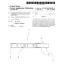
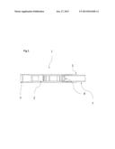
[0009] FIG. 1 is a longitudinal cross-section of an exemplary subassembly of the invention with an intact burst-disc installed, lower end toward the right hand side of the figure.
DETAILED DESCRIPTION
[0010] Generally, the present invention provides a subassembly 1 with at least two pressure sealing mechanisms, comprising (i) a burst disc 4 and (ii) a fitting for a profile plug 6. The burst disc 4 is generally deployed below the profile plug fitting 6 when the subassembly 1 is used, and the inner passage of the subassembly 1 when sealed by either an intact burst disc 4 or a plug in the profile plug fitting 6, or both, does not permit fluid flow from tubing attached below the subassembly 1 through the subassembly 1 to tubing or the wellbore above the subassembly (or packing between the wellbore and the tubing, wherever located).
[0011] The burst disc 4, most typically made of breakable ceramic or similar substance, is designed to be breakable/broken by exertion of force from above the disc 4, such as by increasing fluid pressure within the conduit of attached wellbore tubing above the subassembly 1, while remaining unbroken/unbreakable by pressure exerted on the burst disc 4 from below the disk. Thus, the tubing string into which the subassembly 1 is assembled (not shown, above and below the subassembly 1) can be sealed by the burst disc 4 when it is intact or opened when the burst disc 4 is broken. The burst disc may be broken by exertion of increased pressure from uphole equipment, and the tubing below the subassembly can later be resealed by use of a plug in the profile plug fitting 6 by wireline. If a plug is fitted at the plug fitting 6 and if the burst disc 4 is unbroken, the subassembly provides a redundant double plug to the tubing string, enhancing reliability and safety.
[0012] This selective sealing functionality provides new and non-obvious utility to drilling, completion and other operations, in particular in situations where the lower portion of the wellbore is deviated, non-vertical, or horizontal making the use of wireline plugs impractical. The unitization of the two sealing mechanisms provides a subassembly of short length which does not require additional assembly steps while making or breaking the tubing string.
[0013] The subassembly can be deployed for injecting or removing tubing into a wellbore, in particular a well-bore having a vertical part from surface downward and a connected deviated or horizontal or non-vertical part below the vertical part of the wellbore. This way, the tubing can be sealed from formation pressures by the burst disc during injection of the tubing into the well, and so the burst disc 4 can be in place at a point in the non-vertical part of the wellbore until the bottom end of the tubing string is placed were desired by the operator, at which stage the burst disc 4 can be broken by application of pressure down the tubing's inner conduit, thus opening the tubing's bottom end. In that setting, wireline plugs cannot be deployed because gravity alone will not provide sufficient force to inject the plugged tubing beyond a certain point of travel in a non-vertical direction due to frictional forces between the tubing's outside walls and the wellbore, among other forces. For similar reasons a wireline removal of a plug from a profile fitting in a non-vertical orientation may be difficult or impossible. In an embodiment, the subassembly 1 will be placed at a point on the tubing string such that when the tubing string is placed where the operator wants it, the subassembly is at or above the point where the wellbore changes from vertical to non-vertical directions, although placement of the subassembly will depend upon where the tubing needs to be sealed during removal, which may be dependent upon a number of factors such as tubing length and size, location of packers, location of production zones, location of perforations, pressures and other downhole conditions.
[0014] When removing tubing from such a wellbore, a standard wireline-deployed plug may be set at or near the bottom of the vertical part of the wellbore, and the tubing removed. When the subassembly 1 reaches the bottom of the substantially vertical part of the wellbore, it will be capable of receiving a wireline deployed plug to mechanically seat and seal within the profile fitting 6 of the subassembly 1, and thus seal the tubing during its trip out of the wellbore to surface.
[0015] The subassembly 1 can be run into the wellbore with the burst disc 4 and plug seated and sealed to the profile plug fitting 6 to create a dual barrier. Even though the burst disc 4 could be in position above the plug profile fitting 6, it is more advantageous in operation to place the burst disc 4 below.
[0016] A shaved or slim-hole or special combination burst disc subassembly 1 with smaller diameter, for example 27/8'' O.D. may be used, such that two small diameter tools or strings can be worked through a 41/2'' liner or wellbore, while standard (non-shaved or slim-hole) 2 78'' O.D. assemblies could not.
[0017] It will be apparent to those knowledgeable about drilling, completion, workover and snubbing operations in the oilfield that the use of this invention can be applicable to other oilfield situations, and yet retains its novelty.
[0018] The above-described embodiments of the invention are intended to be examples only. Alterations, modifications and variations can be effected to the particular embodiments by those of skill in the art without departing from the scope of the invention, which is defined solely by the claims appended hereto
User Contributions:
Comment about this patent or add new information about this topic:
Images included with this patent application:
 |  |
| Similar patent applications: | |
| Date | Title |
|---|---|
| 2013-06-20 | Mitigation of hydrates, paraffins and waxes in well tools |
| 2013-07-04 | Release assembly for a downhole tool string and method for use thereof |
| 2013-01-10 | Combination swivel and ball dropper |
| 2013-06-06 | Source spectrum control of nonlinearities in optical waveguides |
| 2013-06-27 | Functionalized surface for flow control device |
| New patent applications in this class: | |
| Date | Title |
|---|---|
| 2019-05-16 | Adjustable flow control device |
| 2017-08-17 | Apparatus and method usable for open-water rigless and riserless plug and abandonment (p&a) work |
| 2016-09-01 | Off-set tubing string segments for selective location of downhole tools |
| 2016-07-07 | Multilateral wellbore stimulation |
| 2016-06-09 | Annulus sealing arrangement and method of sealing an annulus |
| New patent applications from these inventors: | |
| Date | Title |
|---|---|
| 2018-06-07 | Frangible-disc subassembly with novel seat, seal and pressure equalization ports |
| 2016-03-10 | Ceramic rupture dome for pressure control |
| 2016-02-04 | Horseshoe jack for drilling, work-overs and completions |
| 2011-03-03 | Snubbing tubulars from a sagd well |
| Top Inventors for class "Wells" | |
| Rank | Inventor's name |
|---|---|
| 1 | Michael L. Fripp |
| 2 | Jean Marc Lopez |
| 3 | Michael H. Johnson |
| 4 | Jørgen Hallundbaek |
| 5 | Dennis P. Nguyen |