Patent application title: Electric food press processor appliance
Inventors:
Robert Lyle Kindelan (Renton, WA, US)
IPC8 Class: AB02C2500FI
USPC Class:
241 36
Class name: Apparatus with automatic control of comminutor drive
Publication date: 2013-06-20
Patent application number: 20130153696
Abstract:
The present invention may be used to process various foods by pressing
them through a receiving receptacle equipped with a processing disk. A
body may have a plurality of platforms, frames and support configurations
conducive for efficient function. A motor may be in the uppermost section
of the body. A switch of choice may activate the motor and set in motion
the press process. A ball bearing assembly and press assembly may
complete the food press processing function. A receiving receptacle may
receive produce for processing by the press plate and push produce
through a processing disk, cup or sieve. A set of micro switches may
serve to control the electric and mechanical function specific to the
task. A press plate with configurations compatible to the disk selected
may complete the process when the processed produce is dispensed into a
dish or appropriate container.Claims:
1. An electric food press processor for vertically pressing food material
comprising: a body of vertical frames and horizontal platforms of high
density material assembled as a support system for an electric food press
processor; an electric motor provides the mechanical power for processing
food materials; a vertical rod whose upper end is connected to the shaft
of the drive motor; said shoulder abutment of said vertical rod seats
against the upper inner race rim of the ball bearing assembly wherein
appropriate hardware secures the lower inner race firmly contained in a
vice like grip thus forming a rotatable hub when activated in either a
clockwise or counterclockwise direction; the ball bearing assembly a
horizontally placed wherein the inner race as opposed to the outer race,
the latter being the race immobilized by upper and lower platforms, is
free to rotate in whatever direction selected; appropriate hardware
secure the low end of the inner race firmly against the vertical rod
upper shoulder abutment thus locking said vertical rod and said ball
bearing inner race into a rotational mode whenever selected; said
vertical rod is externally threaded to its lower end point wherein it
connects to an internally threaded vertical shaft compatible with
external threads of said vertical rod; a horizontal press plate is
adjoined to said vertical shaft and stabilizing rods; said press plate is
fitted with vertical stabilizing rods on each side of the shaft wherein
the shaft, stabilizing rods and press plate comprise a press assembly; a
bank of external switches initiate control options of which descend,
ascend, stop, and pause/start are externally placed and accessible; a
printed circuit board serves to direct selected function choices, is
programmed to alert the user if a malfunction should result; two
horizontal platforms guide descend and ascend action of the press
assembly; said horizontal upper platform, secured to the frame, has three
holes, one specific to the vertical shaft circumference, and two specific
to the stabilizing rods circumference thus serve as guides and stabilize
descend and ascend motion; said horizontal lower platform of exact
dimensions as the upper said horizontal platform, secured to said frame,
has three holes, one specific to the vertical shaft circumference, and
two specific to the stabilizing rod circumference thus working in
conjunction with the upper horizontal platform as stabilizing factors;
said horizontal platforms have micro switches placed in proximity to each
of said stabilizing rod guide holes; said micro switches serve to
inactivate or activate electric current though the deactivate actually
ends the automation process of the press assembly and it stops; said
micro switch activation does not start the press assembly ascend or
descend, that can be done only by the appropriate switch situated
externally at the top of the food press processor's outer cover, it
activates current to the control switch and thus end the press process
but cannot activate the press process; the upper guide platform is
specific to the ascend function; when said ascend switch is activated
into an automatic mode it ends when the top of the stabilizing rods top
presses against the protruding button tip of the micro switches thus
recessing the button that deactivates electric current thus ending the
ascend motion; conversely, when the descend switch is activated, the
press assembly is put in motion and the press assembly descends; said
stabilizing rods descend until they reach said lower micro switches whose
buttons remain recessed until the stabilizing rods slide past the lower
micro switch recessed tips, when said buttons not longer are in contact
with the stabilizing rods they protrude thus deactivating electric and
the press assembly stops; said press assembly has completed its
descending motion thus food material is dispensed through the processing
receiving receptacle; said processed food is collected from whatever
container has been placed and the process is complete; said electric
current has ended for the descend mode, and will remain so until the
ascend switch is activated and the stabilizing rods ascend and activate
descend by the stabilizing rods contact with the micro switch button
located on the upper horizontal platform; said horizontal lower guide
platform is specific to the descend function when the stabilizing rods
descend below the buttons of the micro switches; said ascend switch when
activated sends the top of the stabilizing rods upward and once they pass
against the micro switch button and recess them electric current can be
activated by the descend control switch but remains inactive until
activated the upper micro switch; as said stabilizing rods descend or
ascend thus making contact to or withdrawing contact from micro switch
buttons that control current within said micro switches, electric current
is activated or deactivated but have no direct activation control to
actually initiate the press plate into action, such action is linked to
external switches accessible from the external cover of the electric food
press processor; programmed into the printed circuit board is a failsafe
feature whereby current is deactivated should both micro switches fail;
said printed circuit board is linked with any malfunction of electric
components should electric failure occur therein an alert light is
activated; said food receiving receptacle is selected according to the
requirements of the operator regarding size, shape and texture; a
processing receptacle that slides and seats onto a horizontal frame for
processing produce into selected configurations according to the
processing disk or cup selected; said receiving platform at the base of
the body for collecting completed processed food matter either on the
horizontal receiving platform or a dish or tray used for that purpose; a
printed circuit board to monitor and direct activation choices, descend,
ascend, pause/start, stop and may include speed control or other
features; a frame that keeps all horizontal platforms securely in place;
an external cover of appropriate material with open entry for easy access
to the horizontal base platform upon completion of the press process
wherein a disk or tray can serve to collect processed food material.
2. The electric food press processor as in claim 1 wherein the receiving receptacle is held in place by a horizontal frame compatible to its size which can be removed horizontally upon completion of the press process after the ascend switch is activated thus withdrawing the press assembly upward and clear of the receiving receptacle.
3. The electric food press processor as in claim 1 wherein a motor is held in place atop the horizontal platform or above the platform whereby its shaft is joined to the vertical threaded rod.
4. The electric food press processor as in claim 1 wherein a steel disk may be inserted into the receiving receptacle orifice and seats against a stop at the bottom most part of the receiving receptacle.
5. The electric food press processor as in claim 1 wherein a processing disk within a containment cup that slides into the receiving receptacle whereby the stop ring at the bottom of the receiving receptacle readies the press process for whatever produce is selected to be pressed.
Description:
BACKGROUND OF THE INVENTION
[0001] 1. Field of the Invention
[0002] This invention relates to electric food preparation and processing food material into various shapes and textures. This invention combines manual and electric powered food preparation as the exclusive method thereby eliminating manual effort as the singular method to achieve desired outcome. Specifically this invention relates to a significantly different processing system wherein food material is pressed vertically and combined with a broad array of attachments the results lead to ease in processing food materials into shapes and textures both beneficial and convenient.
[0003] 2. Description of the Prior Art
[0004] In the past and present, food processors typically rotate horizontally using cutters, slicers and shredding disks or blade attachments to facilitate various repetitive tasks in the preparation of food. To achieve that end a number of parts are incorporated rather than a fixed blade. The present technology is limiting in some respects as some foods to be processed require said processor's parts and attachments to be disassembled to remove incompatible food materials before a different can be processed. The history of the food processor dates back to Germany in 1946 and later a French citizen noted a large amount of time in the kitchen chopping, shredding and mixing and a new addition was born, the bowl with a revolving blade.
[0005] Electric food processors of the type described in the field of the Invention sector have been largely classified into several kinds based on mechanical, structural and electric variances. Essentially the processing aspect involves food material subjected to cutting by a horizontal disk-cutter driven rotationally by a motor within a structural containment apparatus. One kind of which is referred to as a storage type which accommodates the cut pieces within a bowl to collect processed food material, while the other kind is called a cut piece discharge type which is arranged to discharge the cut pieces out of the container.
[0006] In the known electric food processor of the type described, the food processor of the processed discharge type adapted to discharge the food materials out of the container has been generally constituted by a main body in which an electric motor is incorporated, a container placed on the main body, a disk shaped attachment driven by an electric motor for rotation within the container, a disk member positioned below the cutter for rotation in the same direction as that of the cutter so as to discharge the cut pieces processed by the cutter out of the container, a container cover of an opening, and a pusher for pressing food material to be cut towards the cutter through a cylindrical feed tube or charge port provided in part of said container lid, etc. Moreover, the disk-shaped cutter and the disc member for discharging the cut pieces may be adapted to be replaced by an S-shaped cutter so as to enable cutting or shredding within the container.
[0007] The conventional electric food processor of the cut piece discharge variety constructed in the above expressed way is capable of continuously effecting a large amount of cutting without being limited by the size of the container, but there has been such an inconvenience that the material to be processed must be preliminarily cut into small pieces for pushing through the cylindrical charge port of the food processor. Another disadvantage in the known food processor as described above is such that, although it is preferable to rotate the disk-like cutter at low speed to prevent the cut pieces from losing shape, performance of the food processor is undesirably lowered particularly during use of the S-shaped cutter as referred to above.
SUMMARY OF THE INVENTION
[0008] The present invention obviates the drawbacks and difficulties that exist in prior art devices and provides a relatively simple, convenient, reliable and efficient way of processing food material.
[0009] Briefly, in the preferred embodiments disclosed herein, the present invention relates to an electrically-driven food press processor. The mechanical components are activated through a number of initial activation switches, printed circuit board and micro switches. The Initial Activation Switches start the press process electrically and rely on the printed circuit board as a way of eliminating some of the wiring normally found in some small appliances, plus the circuit board signals if an electric component malfunctions. The micro switches activate or deactivate electric current but have no control to initiate press activity on its own. The press components including one horizontal press plate comprise three vertical components, a central shaft and two vertical stabilizing rod and are named the press assembly. The press assembly is activated by a switch from an externally placed bank of switches. The motor, activated by an ascend of descend switch, starts the press process activating the press assembly and the food material having been placed in the receiving receptacle is pressed through a sieve, cutter, dicer, masher, juicer or some other designated attachment chosen for the press processing task.
[0010] The foregoing and other features and advantages of the present invention will become better understood with reference to the following drawings, description, claims and abstract.
BRIEF DESCRIPTION OF THE DRAWINGS
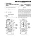
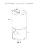
[0011] FIG. 1A. Illustrates the perspective view of the electric food press processor according to the embodiment of the invention. The annotation included in the drawing, 1/9, describe the changes and show the original drawing and the annotated drawing.
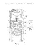
[0012] FIG. 1B. Illustrates another perspective of the electric food press processor according to the embodiment of the invention that illustrates a view of the press assembly making contact with the receiving receptacle, additionally, the annotations included in 2/9 specify those changes clarifying their relationship in later drawings and how they relate to the function of said press assembly.
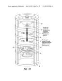
[0013] FIG. 2. Illustrates front view of the invention and includes similar annotation shown in 3/9 specific to press structure.
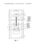
[0014] FIG. 3. Illustrates a perspective of the exterior of the invention and the singular annotation is the drawing number, 4/9.
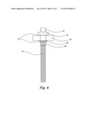
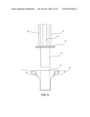
[0015] FIG. 4. Illustrates in a New Sheet a perspective of the ball bearing assembly. This is shown on a New Sheet and demonstrates the relationship between the ball bearing assembly, the vertical shaft, the inner race of the ball bearing, and the way the shoulder of the vertical shaft serves to become an abutment that secures the inner race to the vertical shaft wherein they become the driving force the motor utilizes to descend the press assembly to successfully complete its mission of processing food material through a strictly vertical press process.
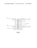
[0016] FIG. 5. Illustrates, in a New Sheet, a perspective of the press assembly in the clearest possible way and how the horizontal platforms, both upper and lower, serve to stabilize the press assembly function.
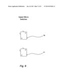
[0017] FIG. 6. Illustrates, in a New Sheet, a perspective of the micro switches for the ascending mode, thus they serve to end or start electric current but cannot activate vertical movement in either direct initially, they control electric current solely in either descend of ascend through activation switches placed externally.
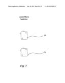
[0018] FIG. 7. Illustrates, in a New Sheet, a perspective of the micro switches for the descend mode, thus they serve to end or start electric current but cannot activate vertical movement in either direct initially, they control electric current solely in either descend of ascend through activation switches placed externally.
[0019] FIG. 8. Illustrates, in a New Sheet, a perspective of a reduced cup when a need for specific food items requiring more concentrated processing emerge.
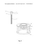
[0020] FIG. 9. Illustrates, in a New Sheet, a perspective of the receiving receptacle, the mesh sieve, and the base platform thus simplifying processing.
DETAILED DESCRIPTION
[0021] The following detailed description represents the best currently contemplated modes of carrying out the invention. The description is not to be taken in a limiting sense, but made merely for the purpose of illustrating the general principles of the invention.
[0022] Referring to FIG. 1A, the inner structure may be made of a sturdy material resistant to pressure and persistent mechanical movement and consist of horizontal platforms 48, 49 of high density material to contain the ball bearing assembly that takes the brunt of upward pressure as the press assembly makes contact with food placed in the food receiving receptacle 45, 51. When the press assembly 50, 43, 44 is activated into a descending action, the top of the stabilizing rods 43 allow the micro switches 52a, 52b to activate ascending current deactivated when the press assembly makes contact with the micro switch contacts 72 and recesses the contacts 72, thus in that specified recess the electric current is deactivated and cannot be activated automatically until a switch located at the top FIG. 3 is pressed. Electric current is deactivated when contact by the top of the stabilizing rods reaches the micro switch 70 and the contacts 72 are recessed. The micro switches are secured to the horizontal platform 56 so that the protruding button 73 in the micro switch is accessible to the outer vertical surfaces of the stabilizing rods 43. When descend is activated by a switch shown in FIG. 3 depicting the external electric food press processor and the row of push buttons 6, is activated, the stabilizing rods 43 in their descend mode glide downward past the contacts, FIG. 7, 75 that have been recessed in the micro switch 53a, 53b frame and the opposite occurs since ascend micro switch contacts FIG. 6, 79 protrude when active and are recessed 75 when electrically inactive. The micro switch function is specific, they activate and deactivate power that is controlled initially by the switches shown in FIG. 3, 6, 7, 8. 9 and cannot initiate activation on their own.
[0023] The electric current is activated to ascend as the stabilizing rods 43 glide downward and the contacts FIG. 6 79 just inside the micro switches 52a, 52b protrude outward and the ascend current to the external switch FIG. 3, 6, 7, 8, 9 bank is activated as the stabilizing rods descend.
[0024] There are few steps involved when the electric food press is used. Illustrated in FIG. 3, switches 6, 7, 8, 9, of which one activates the descend action, one activates the ascend action, one to pause/start, and one to stop action as needed.
[0025] In FIG. 1A, the motor 47 when activated in whatever switch selection is made, rotates the shaft either clockwise or counterclockwise, depending on ascent switch selected, or descent switch selected, however ascend cannot be activated once the press assembly is in its most uppermost position. When the press assembly is in a power to start position, start meaning at the uppermost portion of the mechanical process as shown in FIG. 1A specifically showing 43, 44, 50 set to descend the press assembly 43, 44, 50 having been activated by contact with the micro switches 53a, 53b shown in FIG. 1A. The activation contact linked to the switch of descend 6 shown in FIG. 3 initiates activation of the food processor to descend. If the descend button 6 is accidentally pressed when the press assembly, FIG. 1A 43, 44, 50 is activated nothing will happen since the micro switch 53a, 53b see FIG. 1A, current after the top end of the stabilizing bars 43 are descending and the micro switches, FIG. 1A, 52a, 52b contacts, FIG. 7, 73 protrude in the full descend mode, current has been automatically activated to the ascend switch 7 shown in FIG. 3.
[0026] In FIG. 1A, below the motor 47 is its connecting shaft merged to the threaded rod 42. The threaded rod 42 is secured within the ball bearing assembly 41 inner race 67 which is secured by an upper collar 62, FIG. 4, kept secure to the inner race 67 by a nut 66 and lock washer 64 shown in FIG. 4.
[0027] Horizontal platforms 48, 49 FIG. 1A contain the ball bearing assembly 41 outer race making it immobile which frees the inner race, FIG. 4 making the inner race 67 free to rotate whenever an activation demand is selected. The horizontal platform 48, 49 in FIG. 1A are secured to the frame body in several ways using hardware components and strategically placed vertical braces to prevent upward pressure when the press assembly 43, 44, 50, FIG. 1A pressing downward against food placed into the receiving receptacle 51 FIG. 9 from becoming a malfunction issue as the cellulose density of produce is not such that it can overcome the material density of the food processor body structure.
[0028] In FIG. 1A, the circuit board 57 is directly wired to the micro switches 52a, 52b, 53a, 53b, and the external activation switches 6, 7, 8, 9, FIG. 3, and is like a traffic controller in that it replaces multiple wiring and activates current as activation sources are contacted.
[0029] In FIG. 1A, the receiving receptacle 51 is filled partially of yet to be processed food items, after the press assembly has completed its task the food selected is pushed through the cup or processing disk by configured spine like projections that push through and past the dicing, slicing, meshing, cubing or juicing processing receptacle and force the processing result onto the bottom platform 46 FIG. 1A or into an appropriate container chosen by the food preparer.
[0030] In FIG. 4, the externally threaded rod's collar 62, and washer 64 and nut 66 keep the upward pressure when the press is in descend mode from overcoming the ball bearing assembly 41 while the platforms 48,49 keeps the ball bearing assembly 41 in a containment mode. The outer race is checked by the containment platforms 48, 49 FIG. 1A keeping the ball bearing assembly stable. The upper end of the threaded rod 65 is open 61 FIG. 4 and the shaft of the motor 47 FIG. 1A fits securely within its inner walls and may be held in place by a horizontal rod through the shaft and upper fitting.
[0031] While the invention has been fully shown and described with reference to the illustrated embodiments thereof, it will be understood by those skilled in the art that the foregoing and targeted changes in form and details may be made without departing from the character and scope of the invention.
User Contributions:
Comment about this patent or add new information about this topic:
| People who visited this patent also read: | |
| Patent application number | Title |
|---|---|
| 20130224808 | PROCESS AND APPARATUS FOR PRODUCING ETHYLENE VIA PREPARATION OF SYNGAS |
| 20130224807 | METHODS OF PRODUCING CARBOXYLIC ACIDS |
| 20130224806 | Method for Producing an L-Amino Acid Using a Bacterium of the Enterobacteriaceae Family |
| 20130224805 | System and Method for Converting Cellulosic Biomass into a Sugar Solution |
| 20130224804 | EXPRESSION OF STEADY STATE METABOLIC PATHWAYS |
Images included with this patent application:
 |  |
 |  |
 |  |
 |  |
 |  |
 |
| Similar patent applications: | |
| Date | Title |
|---|---|
| 2010-05-06 | Electric pepper can |
| 2012-09-27 | Filler recovery processes |
| 2009-12-31 | Electric seasoning mill |
| 2013-10-10 | Food processor |
| 2013-12-26 | Method for blending food or beverages |
| New patent applications in this class: | |
| Date | Title |
|---|---|
| 2017-08-17 | Grinder for preparing brewing materials |
| 2016-12-29 | Detecting passing of unintended objects through throat of under-sink disposal |
| 2016-05-26 | Mixer feeder |
| 2016-05-05 | Air gap switch for a waste disposal water supply system |
| 2016-04-21 | Comminuting machine drive system |
| Top Inventors for class "Solid material comminution or disintegration" | |
| Rank | Inventor's name |
|---|---|
| 1 | Tai Hoon K. Matlin |
| 2 | Charles Sued |
| 3 | Aron Abramson |
| 4 | Knut Kjaerran |
| 5 | Hartmut Pallmann |