Patent application title: HEADREST AND WORK SURFACE APPARATUS
Inventors:
Guadalupe Chavira (Tolleson, AZ, US)
IPC8 Class: AA47B8506FI
USPC Class:
108 12
Class name: Horizontally supported planar surfaces convertible reorientatable support
Publication date: 2013-06-20
Patent application number: 20130152828
Abstract:
A portable collapsible apparatus serves as either a headrest or work
surface. A base may be anchored under the thighs of a seated user or by
the user's feet. An extendible element is adjusted in length from the
base to position a platform at a height convenient for the platform to
serve as a work surface or as a headrest. For the latter, a cushion is
detachably attachable to the platform to serve in the manner of a pillow
when the apparatus is used as a headrest. Adjustable pivot mechanisms
interconnect the base and the platform with the extendible element to
locate the platform at a convenient angle for its use as a headrest or
work surface. Adjustable locks accommodate extension and retraction of
the extendible element to locate the height of the platform relative to
the base. The pivot mechanisms and adjustable locks also accommodate
collapse of the apparatus by contracting the extendible element and by
placing the extendible element essentially adjacent both the base and the
platform.Claims:
1. A portable collapsible apparatus serving as either a headrest or work
surface, said apparatus comprising: a) a base maintainable in position
selectively by either the user's thighs or feet; b) a telescoping member
attached to said base at a settable angle; and c) a platform supported by
said telescoping member at a settable angle and serving as either a work
surface or headrest.
2. The apparatus as set forth in claim 1 including a cushion removably attached to said platform for supporting the user's face.
3. The apparatus as set forth in claim 2 wherein said cushion includes an opening for breathing and wherein said platform includes at least one aperture generally coincident with said opening to provide an air path for the user.
4. The apparatus as set forth in claim 3 wherein said cushion includes a pocket for receiving a section of said platform to mount said cushion on said platform.
5. The apparatus as set forth in claim 4 wherein said cushion is generally ring shaped.
6. The apparatus as set forth in claim 4 wherein said cushion includes a ring-like element of foam material and a removable cover extending about said element of foam material.
7. The apparatus as set forth in claim 6 wherein said pocket is formed by said cover.
8. The apparatus as set forth in claim 1 including a first pivot mechanism interconnecting said base with said telescoping member and a second pivot mechanism interconnecting said telescoping member with said platform.
9. The apparatus as set forth in claim 8 wherein each of said first and second pivot mechanisms is lockable to establish the respective settable angles.
10. The apparatus as set forth in claim 9 wherein said first pivot mechanism accommodates pivotal movement of said telescoping member to a location adjacent said base and wherein said second pivot mechanism accommodates pivotal movement of said telescoping member to a location adjacent said platform to collapse said apparatus.
11. The apparatus as set forth in claim 10 wherein said telescoping member is collapsible to locate said base and said platform in proximity to one another when said apparatus is in the collapsed state.
12. The apparatus as set forth in claim 1 wherein said telescoping member includes a plurality of segments extendible and retractable with respect to one another.
13. The apparatus as set forth in claim 12 including a selectively actuatable lock for locking one of said segments with an adjacent one of said segments to maintain said telescoping member at a selected length.
14. The apparatus as set forth in claim 13 including a plurality of said actuatable locks, one of said actuatable locks being disposed at an open end of each of said telescoping member.
15. A portable collapsible apparatus serving as either a headrest or work surface, said apparatus comprising: a) a base maintainable in position selectively by either a user's thighs or feet; b) an extendible element attached to said base at a settable angle; and c) a platform supported by said extendible element at a settable angle and serving as either a work surface or headrest.
16. The apparatus as set forth in claim 15 including a headrest, said headrest including a cushion having an opening therein and removably attached to said platform for supporting the user's face, said platform including at least one aperture generally coincident with said opening to provide a passageway for the user's breathing.
17. The apparatus as set forth in claim 16 wherein said cushion is of compressible material to softly cradle the user's head and including a cover for said material, said cover including a pocket for partially receiving said platform to maintain said cushion removably secured to said platform.
18. The apparatus as set forth in claim 16 including a first pivot mechanism interconnecting said base with said extendible element and a second pivot mechanism interconnecting said extendible element with said platform, each of said first and second pivot mechanisms being lockable to establish and maintain the respective settable angles.
19. The apparatus as set forth in claim 18 wherein said first pivot mechanism accommodates movement of the extendible element to a location adjacent said base and wherein said second pivot mechanism accommodates'pivotal movement of said extendible element to a location adjacent said platform to collapse said apparatus.
20. The apparatus as set forth in claim 15 wherein said extendible element includes at least one actuatable lock for locking said extendible element in a selected extended or collapsed length.
Description:
CROSS REFERENCE TO RELATED APPLICATIONS
[0001] The present application includes subject matter disclosed in and claims priority to a provisional application entitled "Support Apparatus", filed Dec. 14, 2011 and assigned Ser. No. 61/570,496, describing an invention made by the present inventor.
BACKGROUND OF THE INVENTION
[0002] 1. Field of the Invention
[0003] The present invention relates to a combination headrest and work surface apparatus and, more particularly, to a portable collapsible apparatus serving as either a headrest or a work surface.
[0004] 2. Description of Related Prior Art
[0005] Travel, whether by land, water or air, is generally of a duration in excess of one hour. During this travel time, various passengers prefer to sleep but such sleep is generally uncomfortable in the seats available. To increase the degree of comfort for sleeping, various cushions have been developed to be placed between the backrest of the seat and the head. Most notable of these cushions are horseshoe-shaped that are mounted partly about the neck of a user. These horseshoe-shaped cushions may be inflatable for use and thereby the firmness may be adjusted. During non-use, the air may be evacuated to permit collapse or folding into a relatively small space for storage and travel purposes.
[0006] During periods of travel, irrespective of the mode of transportation, many travelers wish to do work, whether writing or working with a laptop computer, tablet, etc. Generally, the only work surface for these purposes available is a tray supported from the back of the seat in front. The height of such tray and its proximity to a user is often not optimal and when used for such purposes tends to cause fatigue. The alternative is for the user to use his/her lap as a supporting surface. This option also is generally far from optimal.
SUMMARY OF THE INVENTION
[0007] The present invention is directed to apparatus that may be used anywhere to provide a work surface or a headrest for a user. The base of the apparatus is anchored beneath a user's thighs when sitting or by a user's feet, whether sitting or standing. An extendible element, such as a telescoping device, supports a platform. The platform may serve as a work surface or, with an added cushion, as a headrest. The height of the platform may be set at a height convenient to a user by locking the extendible element to an appropriate length. A first pivot mechanism is disposed intermediate the base and the extendible element to permit setting of the angle of the extendible element relative to the base that is comfortable to a user. A second pivot mechanism is disposed between the extendible element and the platform to accommodate setting the angle of a platform at an angle comfortable to the user. A detachable cushion may be used with the platform in the manner of a pillow upon which the user may rest his/her head. To accommodate the user placing his/her face on the cushion, an opening in the cushion is provided which corresponds with an aperture in the platform and in combination provide a passageway for the breath of the user. By retracting the extendible element, the distance between the base and the platform may be significantly shortened. The first and second pivot mechanism accommodate rotation of the base and the platform to locations essentially adjacent the extendible element. Thereby, the apparatus is collapsed and formed into minimal height, width and length configuration for ease of travel and storage.
[0008] It is therefore a primary object of the present invention to provide apparatus serving either as a work surface or as a headrest.
[0009] Another object of the present invention is to provide apparatus supporting a work surface at a location convenient for a user.
[0010] Still another object of the present invention is to provide a headrest adjustable to a height and angular orientation that is comfortable for a user.
[0011] Yet another object of the present invention is to provide a detachably attachable cushion for use with a headrest.
[0012] Yet another object of the present invention is to provide a passageway for breathing should a user wish to rest his/her head facedown on a headrest.
[0013] A further object of the present invention is to provide a base for a combination work surface and headrest apparatus that is stabilized and retained in place by the weight of a user's thighs or the weight exerted by a user's feet.
[0014] A still further another object of the present invention is to provide apparatus for pivotally attaching a base and a platform to an extendible element for placing the platform at a location convenient and comfortable for a user.
[0015] A yet further object of the present invention is to provide a portable collapsible apparatus supporting a platform useable as a work surface or as a headrest.
[0016] These and other objects of the present invention will become apparent to those skilled in the art as the description thereof proceeds.
BRIEF DESCRIPTION OF THE DRAWINGS
[0017] The present invention will be described with greater specificity and clarity with reference to the following drawings, in which:
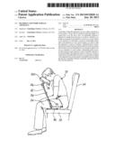
[0018] FIG. 1 illustrates a user seated upon a seat as might be found in an aircraft, vessel, bus or car, using the present invention in the manner of a work surface;
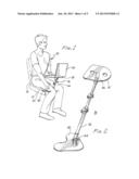
[0019] FIG. 2 illustrates the portable collapsible apparatus of the present invention that may serve as a work surface or as a headrest;
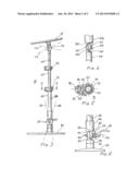
[0020] FIG. 3 is a side elevational view of the apparatus;
[0021] FIG. 4 is a detailed view of a first pivot mechanism interconnecting the base and the extendible element;
[0022] FIG. 5 is a cross-sectional view taken along lines 5-5, as shown in FIG. 3 and illustrating a locking device for the extendible element;
[0023] FIG. 6 is a detailed view of a second pivot mechanism disposed intermediate the extendible element and the platform;
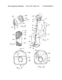
[0024] FIG. 7 illustrates use of the present invention as a headrest;
[0025] FIG. 8 illustrates the cushion detachably attachable to the platform;
[0026] FIG. 9 is a rear view of the cushion;
[0027] FIG. 10 is a front view of the cushion;
[0028] FIG. 11 is a view taken along lines 11-11, as shown in FIG. 9;
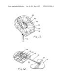
[0029] FIG. 12 illustrates the cushion mounted on the platform;
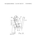
[0030] FIG. 13 illustrates a variant of use of the present invention as a headrest; and
[0031] FIG. 14 illustrates the collapsed state of the present invention.
DESCRIPTION OF THE PREFERRED EMBODIMENT
[0032] Referring to FIG. 1, there is illustrated a user 10 of the present invention seated on a seat cushion 12. The cushion may be coupled with a back rest 14. The combination of seat and back rest are representative of seats present on airliners, buses, cars, and other modes of transportation. Apparatus 16 provides to user 10 a platform 18 upon which a laptop computer, such as laptop 20, may rest and permit user 10 to perform work or other functions on the laptop.
[0033] Referring jointly to FIGS. 1 and 2, further details of apparatus 16 will be described. A base 30 may rest on seat cushion 12 beneath the thighs (22,24) of user 10. Thereby, the base is firmly anchored upon the seat to a degree sufficient to support apparatus 16. An extendible element 32 is pivotally connected to base 30 by pivot mechanism 34. A platform 18 is attached to the upper end of extendible element 32 via a pivot mechanism 36. As illustrated in FIG. 1, extendible element 32 extends away from the torso of user 10 to locate platform 18 at a comfortable distance. Platform 18 is pivotally located to support laptop 20 at a comfortable angle to permit ease of use of the laptop computer or perform other functions for work or pleasure. The height of platform 18 relative to base 30 is adjustable by adjusting the length of extendible element 32 to place platform 18 at a comfortable height for user 10.
[0034] Referring jointly to FIGS. 3, 4, 5, and 6, further details attendant apparatus 16, and particularly extendible element 32, will be described. Pivot mechanism 34, disposed at the lower end of extendible element 32 interconnects the extendible element with base 30. The pivot mechanism accommodates positioning the extendible element relative to the base at any position within the angle defined by dashed lines 38,40. As particularly shown in FIG. 4, boss 42, extending upwardly from base 30, includes a tang 44 having a central aperture and a plurality of radially extending grooves 46 defining ridges therebetween. Similarly, lower end 48 of the extendible element includes a tang 50 having a central aperture and a plurality of radially extending grooves 52 defining ridges therebetween. Grooves 46 mate with the ridges between grooves 52 to prevent rotational movement of tangs 44,50 relative to one another and about a common axis 54. A spring loaded tab 56 acting through shaft 57 draws the tangs toward one another into a locking engagement to prevent relative rotational movement therebetween. Upon release of lock 58, tangs 44,50 may disengage and the angular orientation of extendible element 32 may be altered relative to base 30 for the benefit of the user, as shown in FIG. 1.
[0035] Extendible element 32 may be formed by three telescoping tubes 60, 62 and 64. In the collapsed state of the extendible element, the length between pivot mechanism 34 and pivot mechanism 36 is minimal and generally commensurate with the longest of the tubes. By employing telescoping tubes (or telescoping members or other members longitudinally repositionable relative to one another) to define the extendible element, the height of platform 18 above base 30 may be readily adjusted for the comfort of the user and as a function of the use to be required of apparatus 16.
[0036] To maintain the segments of the extendible element, whether it be tubes 60, 62 and 64, or other segments extendible relative to one another, a locking mechanism(s) may be incorporated to temporarily set the length of the extendible element. For example, a locking device 70 may be incorporated to positionally fix tube 62 relative to tube 60. Such locking devices are commercially available and any of several types may be incorporated. For example, these may be of the lever type, as depicted in FIG. 5, or of the rotatable ring type to jam the tubes and thereby maintain them in fixed position with respect to one another. As shown in FIG. 5, a housing 72 includes a partial cylindrical cavity 74 for partially encircling tube 60. A lever 76 is pivotally secured to housing 72 by a pin 78 or the like. The lever includes a non-symmetrical lobe 80. The lobe engages a peg 82 in contact with tube 62 through a slot 84 in the sidewall of tube 60. As illustrated, when lever 76 is in the position shown, lobe 80 will urge peg 82 into contact with the exterior surface of tube 62. This contact, being of a friction type, will discourage longitudinal movement of tube 62 relative to tube 60. Upon rotational movement of lever 76 in a clockwise direction, as viewed in FIG. 5, the force exerted by lobe 80 will be reduced and peg 82 will no longer be in frictional engagement with tube 62 and thereby permit longitudinal movement of tube 62 relative to tube 60. Thus, the extension of tube 62 relative to tube 60 is settable. A locking device 90, essentially equivalent to locking device 70 illustrated in FIG. 5, similarly locks and unlocks longitudinal movement of tube 64 relative to tube 62.
[0037] While three telescoping tubes are illustrated, it is to be understood that a lesser or greater number of telescoping tubes or longitudinally extending members can be employed to satisfy the height requirements of apparatus 16. Pivotal mechanism 36, interconnecting extendible element 32 and platform 18, is illustrated in further detail in FIG. 6. The pivot mechanism includes a tang 100 extending from tube 64, which tang is essentially similar to tang 44 shown in FIG. 4; it includes a plurality of radially aligned grooves 102 with ridges therebetween. A further tang 104 extends from boss 106 attached to the bottom of platform 18. Tang 104 includes a plurality of radially aligned grooves 108 with ridges therebetween. A bolt 110, or the like, extends through the center apertures of tangs 100 and 104. A wing nut 112 is in threaded engagement with bolt 110 to urge tang 104 into engagement with tang 100. As depicted in FIG. 3, platform 18 may be rotatable relative to extendible element 32 through an angle represented by dashed lines 114,116. Such pivotal movement is accomplished by partially unthreading wing nut 112 to permit separation between tangs 100 and 104. Once the angle sought is achieved, the wing nut is tightened and the ridges formed by grooves 102, engaging grooves 108, preclude further rotational movement of boss 106 and platform 18 relative to tube 64.
[0038] Referring jointly to FIGS. 7, 8, 9, 10, 11, and 12, there is shown a cushion 120 for use with apparatus 16 to serve in the manner of a headrest. The cushion includes a foam ring 122 that serves in the manner of a pillow to permit comfortable resting thereupon by a user's face. The interior surface of the foam ring is generally cone-shaped to permit nesting of the user's face adjacent the large opening of the cone. To protect the cone and to provide a surface that is not only comfortable to a user's skin but also washable, a cover 124 is formed about the foam ring. This cover includes an opening 126 coincident with the small end of the funnel-like opening in the foam ring. Thereby, a user can easily breathe.
[0039] Cushion 120 is detachably attachable to platform 18 by forming a pocket at the upper end of the cushion by a flap 128. The upper end of platform 18 is inserted into the pocket formed by flap 128. One or more holes 130,132 are disposed in platform 18 generally coincident with opening 126 in the cushion to accommodate air flow through the platform as well as through the cushion.
[0040] To enhance washing of cover 124, it is removable from about foam ring 122. Such removal is effected by generally circular end 134 overlapping a commensurately configured circular end 136. These ends may be detachably attached to one another by hook and loop fasteners, such as the type sold under the trademark Velcro®. After detachment, the foam ring may be readily removed from within the cover. After washing or other cleaning, cushion 120 is reassembled by placing the foam ring within the cover and securing the circular ends of the cover to one another.
[0041] As particularly shown in FIG. 7, it illustrates an alternate way in which the present invention may be used as a headrest for a traveler. User 10, seated upon seat cushion 12, places his/her feet upon base 30 on either side of boss 42. Pivot mechanism 34 is adjusted to orient extendible element 32 toward the user's face. Additionally, locking devices 70 and 90 may be adjusted to obtain an appropriate length of the extendible element. Pivot mechanism 36 is adjusted to position platform 18 in general alignment with the face of user 10. As illustrated, cushion 120 is mounted upon the platform by placing the upper part of the platform within the pocket formed in the cushion. With this arrangement, base 30 is stabilized and will not move unless the user's feet are moved. This permits the user to lean against cushion 120 without any commensurate movement of apparatus 16.
[0042] As further shown in FIG. 13, apparatus 16 may also used in a different manner by user 10 seated upon a seat cushion 12. Herein, base 30 is placed under the thighs, of which thigh 24 is shown, of the user to stabilize and positionally maintain the base. Extendible element 32 is adjusted in length by locking devices 70 and 90 to locate platform 18 and supported cushion 120 at a comfortable height for the user to rest his/her head upon the cushion. Depending upon how much the user may wish to lean forward, pivot mechanisms 34,36 are released and reset until a comfortable position for cushion 120 is achieved.
[0043] Referring to FIG. 14, the collapsible and portable feature of apparatus 16 will be described. Pivot mechanism 34 is reset to essentially align extendible element 32 parallel with the top surface of base 30. Similarly, pivot mechanism 36 is reset to align extendible element 32 with the planar surface of platform 18. Locking devices 70 and 90 are unlocked to permit collapse of the extendible element to minimize the distance between base 30 and platform 18.
User Contributions:
Comment about this patent or add new information about this topic:
| People who visited this patent also read: | |
| Patent application number | Title |
|---|---|
| 20150080749 | Devices, Systems, and Methods for Visually Depicting a Vessel and Evaluating Treatment Options |
| 20150080748 | Method and System for Predicting Cardiovascular Events |
| 20150080746 | SYSTEMS AND METHODS FOR COORDINATING MUSCULOSKELETAL AND CARDIOVASCULAR OR CEREBROVASCULAR HEMODYNAMICS |
| 20150080745 | Scanned Laser Vein Contrast Enhancer Using a Single Laser |
| 20150080744 | METHOD AND SYSTEM FOR ASSESSING PRETERM BIRTH AND OTHER PATHOLOGIES |
Images included with this patent application:
 |  |
 |  |
 |  |
| Similar patent applications: | |
| Date | Title |
|---|---|
| 2013-03-21 | Desk board raising apparatus |
| 2013-05-23 | Standing support apparatus |
| 2013-03-14 | Grommet assembly for work surfaces |
| 2013-04-25 | Multifunctional workstation apparatus |
| 2009-12-10 | Keyboard and mouse support |
| New patent applications in this class: | |
| Date | Title |
|---|---|
| 2016-05-12 | Palletizing mobile drive units |
| 2013-11-28 | Frame type workstation configurations |
| 2012-01-12 | Workbench with saw horse |
| 2011-10-06 | Table |
| 2011-09-22 | Convertible table and method of use |
| Top Inventors for class "Horizontally supported planar surfaces" | |
| Rank | Inventor's name |
|---|---|
| 1 | Mitch Johnson |
| 2 | Wendell Peery |
| 3 | David C. Winter |
| 4 | William P. Apps |
| 5 | Mustafa A. Ergun |