Patent application title: ELECTRONIC DEVICE WITH COOLING MODULE
Inventors:
Qiang Chen (Shenzhen City, CN)
Assignees:
HON HAI PRECISION INDUSTRY CO., LTD.
HONG FU JIN PRECISION INDUSTRY (ShenZhen) CO., LTD.
IPC8 Class: AG06F120FI
USPC Class:
36167933
Class name: Computer related housing or mounting assemblies for computer memory unit disk drive type
Publication date: 2013-06-06
Patent application number: 20130141864
Abstract:
An electronic device includes a housing. A motherboard is arranged in a
first end of the housing. A hard disk drive area is arranged at a second
end of the housing. A cooling module is arranged at the housing between
the motherboard and the hard disk drive area. The cooling module includes
a chassis and a semiconductor chilling plate received in the chassis. An
outside airflow flows through the hard disk drive area, and then flows
through the semiconductor chilling plate to be cooled. The cooled airflow
is driven to flow through the motherboard.Claims:
1. An electronic device comprising: a housing; a motherboard arranged at
a first end of the housing; a hard disk drive area arranged at a second
end of the housing; and a cooling module arranged in the housing between
the motherboard and the hard disk drive area, the cooling module
comprising a chassis and a semiconductor chilling plate received in the
chassis; wherein an outside airflow flows through the hard disk drive
area to cool the hard disk drive area, and then flows through the
semiconductor chilling plate to be cooled, the cooled airflow is driven
to flow through the motherboard.
2. The electronic device of claim 1, wherein a first heat sink is received in the chassis and attached to a heat side of the semiconductor chilling plate, a second heat sink is received in the chassis and attached to a cool side of the semiconductor chilling plate.
3. The electronic device of claim 2, wherein the chassis comprises a first side plate facing the motherboard, and a second side plate facing the hard disk drive area, two first fans are arranged on the first side plate aligning with the second heat sink, the second side plate defines two first inlets aligning with the second heat sink, a first airflow coming from outside flows through the hard disk drive area to cool the hard disk drive area, then flows into the cooling module through the first inlets to be cooled by the semiconductor chilling plate and the second heat sink, the cooled first airflow flows to the motherboard through the first fans to cool the motherboard.
4. The electronic device of claim 3, wherein the second side plate further defines a second inlet aligning with the first heat sink, a second fan is placed at one end of the chassis adjacent to the housing, the housing defines a through hole aligning with the second fan to expose the second fan, a second airflow coming from outside flows through the hard disk drive area to cool the hard disk drive area, then flows into the cooling module through the second inlet to cool the first heat sink, the heated second airflow flows to outside through the second fan and the through hole.
5. The electronic device of claim 4, wherein the semiconductor chilling plate, the first fans, and the second fan are electrically connected to the motherboard to be powered by the motherboard.
6. The electronic device of claim 5, wherein the motherboard senses the temperature in the housing to adjust the speeds of the first and second fans and the refrigerating output of the semiconductor chilling plate.
7. The electronic device of claim 1, wherein the chassis is made of adiabatic material.
Description:
BACKGROUND
[0001] 1. Technical Field
[0002] The present disclosure relates to electronic devices, and particularly, to an electronic device with a cooling module.
[0003] 2. Description of Related Art
[0004] Mini electronic devices, such as mini computers, are increasingly used in more fields. During operation, the electronic components generate a lot of heat in the housings of the mini electronic devices. A common method for dissipating the heat is to use fans. However, the housing of the mini electronic device is too small to arrange enough fans for heat dissipating.
BRIEF DESCRIPTION OF THE DRAWINGS
[0005] Many aspects of the present embodiments can be better understood with reference to the following drawing. The components in the drawing are not necessarily drawn to scale, the emphasis instead being placed upon clearly illustrating the principles of the present embodiments. Moreover, in the drawing, like reference numerals designate corresponding parts throughout the several views.
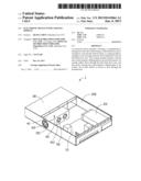
[0006] FIG. 1 is an assembled, isometric view of an electronic device, according to an exemplary embodiment, with certain components omitted for clarity.
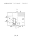
[0007] FIG. 2 is a cross-sectional, top plan view of FIG. 1.
DETAILED DESCRIPTION
[0008] The disclosure, including the accompanying drawing, is illustrated by way of examples and not by way of limitation. It should be noted that references to "an" or "one" embodiment in this disclosure are not necessarily to the same embodiment, and such references mean at least one.
[0009] Referring to FIG. 1 and FIG. 2, an embodiment of an electronic device 1 includes a housing 100, a motherboard 10 arranged in a first end of the housing 100, a power supply unit 20 arranged in the first end of the housing 100 and adjacent to the motherboard 10, a hard disk drive area 30 located in a second end of the housing 100 for mounting hard disk drives, and a cooling module 40 arranged in a middle of the housing 100 and between the motherboard 10 and the hard disk drive area 30.
[0010] The cooling module 40 includes a chassis 41 defining a receiving space 410, and a semiconductor chilling plate 42 received in the receiving space 410. A first heat sink 43 is received in the receiving space 410 and attached to a heat side of the semiconductor chilling plate 42. A second heat sink 44 is received in the receiving space 410 and attached to a cool side of the semiconductor chilling plate 42. The chassis 41 includes a first side plate 411 facing the motherboard 10, and a second side plate 412 facing the hard disk drive area 30. The first side plate 411 defines two through holes 413 aligning with the second heat sink 44 for arranging two first fans 50. The second side plate 412 defines two first inlets 4121 aligning with the second heat sink 44, and a second inlet 4122 aligning with the first heat sink 43. A second fan 60 is placed at one end of the chassis 41 adjacent to the housing 100. The housing 100 defines a through hole 101 aligning with the second fan 60, to expose the second fan 60.
[0011] The chassis 41 is made of adiabatic material.
[0012] The semiconductor chilling plate 42, the first fans 50, and the second fan 60 are electrically connected to the motherboard 10, to be powered by the motherboard 10. The motherboard 10 can sense the temperature in the housing 100 to adjust the speeds of the first and second fans 50 and 60 and the refrigerating output of the semiconductor chilling plate 42.
[0013] When the electronic device 1 operates, a first airflow A coming from outside flows through the hard disk drive area 30 to cool the hard disk drives, then flows into the cooling module 40 through the first inlets 4121 to be cooled by the semiconductor chilling plate 42 and the second heat sink 44. The cooled first airflow A flows to the motherboard 10 through the first fans 50 to cool the motherboard 10.
[0014] A second airflow B coming from outside flows through the hard disk drive area 30 to cool the hard disk drives, then flows into the cooling module 40 through the second inlets 4122 to cool the first heat sink 43. The heated second airflow B is guided by the second fan 60 to flow to outside through the through hole 101.
[0015] In this embodiment, the electronic device 1 utilizes the semiconductor chilling plate 42 to cool the housing 100, which can dissipate heat effectively and reduce quantity of fans.
[0016] Even though numerous characteristics and advantages of the embodiments have been set forth in the foregoing description, together with details of the structure and function of the embodiments, the disclosure is illustrative only, and changes may be made in detail, especially in the matters of shape, size, and arrangement of parts within the principles of the present disclosure to the full extent indicated by the broad general meaning of the terms in which the appended claims are expressed.
User Contributions:
Comment about this patent or add new information about this topic:
| People who visited this patent also read: | |
| Patent application number | Title |
|---|---|
| 20220030173 | IMAGE SENSOR AND ELECTRONIC DEVICE INCLUDING IMAGE SENSOR |
| 20220030172 | METHOD, IMAGING APPARATUS AND COMPUTER PROGRAM PRODUCT FOR POSITIONING IMAGING-RELEVANT COMPONENTS |
| 20220030171 | ENDOSCOPE WITH PANNABLE CAMERA AND RELATED METHOD |
| 20220030170 | Imaging Apparatus And Display Control Method Thereof |
| 20220030169 | DISPLAY APPARATUS AND IMAGE PICKUP APPARATUS |
Images included with this patent application:
 |  |
 |
| Similar patent applications: | |
| Date | Title |
|---|---|
| 2010-12-30 | Rotatable cooling module |
| 2011-06-09 | Electronic module |
| 2011-07-14 | Electronic module |
| 2012-06-21 | Server with fan module |
| 2012-07-26 | Electronic device |
| New patent applications in this class: | |
| Date | Title |
|---|---|
| 2016-07-14 | Disk drive carriers and mountable hard drive systems with improved air flow |
| 2016-06-30 | Front access server |
| 2016-06-09 | Electronic device with bracket for disk drive |
| 2016-05-26 | Key-value drive ultrathin sata connector |
| 2016-05-12 | Distributed data storage system and method |
| New patent applications from these inventors: | |
| Date | Title |
|---|---|
| 2014-07-03 | Softkey magnification on touch screen |
| 2013-06-20 | Mouse assembly |
| 2013-01-31 | Support for holding mutiple displays and display device with same |
| 2012-06-14 | Notebook computer |
| 2012-04-19 | Computer enclosure |
| Top Inventors for class "Electricity: electrical systems and devices" | |
| Rank | Inventor's name |
|---|---|
| 1 | Zheng-Heng Sun |
| 2 | Levi A. Campbell |
| 3 | Li-Ping Chen |
| 4 | Robert E. Simons |
| 5 | Richard C. Chu |